Advertisement
Warranty, Service & Repair
If for some reason your product must be returned for factory ser-
vice, contact Dwyer Inc. at (219)879-8000 to receive a Material
Return Authorization number (MRA), providing the following
information:
1. Part Number, Serial Number
2. Name and telephone number of someone who can answer
technical questions related to the product and its application.
3. Return Shipping Address
4. Brief Description of the Symptom
5. Brief Description of the Application
Once you have received a Material Return Authorization number,
ship the product prepaid in its original packing to:
Dwyer Instruments Inc.
PO Box 373
102 Indiana Hwy, 212
Michigan City, IN 46361
Please include the information about the malfunction with your
product.
This information enables our service technicians to
process your repair order as quickly as possible.
WARRANTY
Step One
About this Manual:
PLEASE READ THE ENTIRE MANUAL PRIOR TO
INSTALLING OR USING THIS PRODUCT.
includes information on all models of Dwyer Thermal Dispersion
Flow Switches: TDS series. Please refer to the part number locat-
ed on the switch label to verify the exact model which you have
purchased.
User's Responsibility for Safety:
Dwyer manufactures a wide range of flow switches and technolo-
gies. While each of these sensors is designed to operate in a wide
variety of applications, it is the user's responsibility to select a sen-
sor model that is appropriate for the application, install it properly,
perform tests of the installed system, and maintain all components.
The failure to do so could result in property damage or serious
injury.
Proper Installation and Handling:
Because this is an electrically operated device, only properly-
trained staff should install and/or repair this product. Use a proper
sealant with all installations. Never overtighten the sensor within
the fitting, beyond a maximum of 80 inch-pounds torque. Always
check for leaks prior to system start-up.
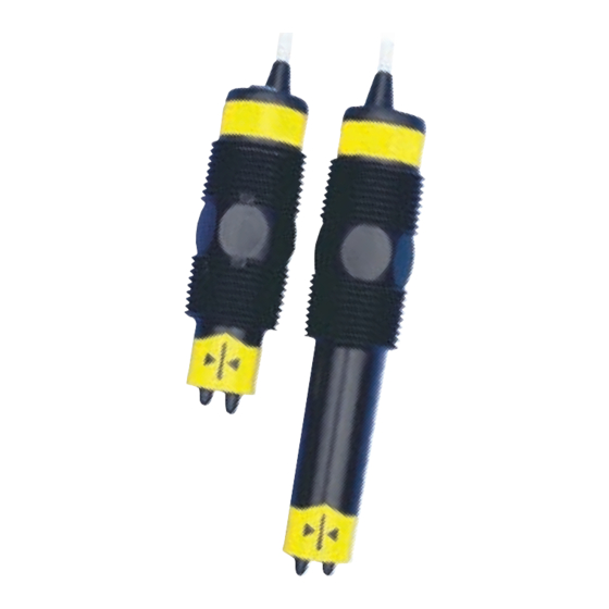
Thermal Dispersion
Flow Switch
TDS Series
Owner's Manual
I P
68
Version 2.0.1A
All rights reserved
Material Compatibility:
The TDS series sensors are available in two different wetted materials.
This manual
Models TDS 1__ are made of Polypropylene (PP) with Ryton tips.
Models TDS 2__ are made of Polyvinylidene Fluoride (PVDF). Make
sure that the model you have selected is compatible with the application
liquid. To determine the chemical compatibility between the sensor and
its application liquids, refer to an industry reference such as the
Compass Corrosion Guide (available from Compass Publications,
phone 858-589-9636).
Wiring and Electrical:
The supply voltage used to power the sensor should never exceed a
maximum of 36 volts DC. Electrical wiring of the sensor should be
performed in accordance with all applicable national, state, and
local codes.
Flammable, Explosive and Hazardous Applications:
DO NOT USE THE TDS SERIES GENERAL PURPOSE FLOW
SWITCHES IN HAZARDOUS LOCATIONS.
The rating for the relay is 120 VAC/60 VDC @ 1A. For CE
rated applications, the relay rating is 60 VAC/60 VDC @ 1A.
Dwyer's Thermal Dispersion flow switches are not recom-
mended for use with electrically charged application liquids.
For most reliable operation, the liquid being measured may
need to be electrically grounded.
WARNING
Advertisement
Table of Contents

Subscribe to Our Youtube Channel
Related Manuals for Dwyer Instruments TDS Series


Summary of Contents for Dwyer Instruments TDS Series
- Page 1 About this Manual: Material Compatibility: PLEASE READ THE ENTIRE MANUAL PRIOR TO The TDS series sensors are available in two different wetted materials. INSTALLING OR USING THIS PRODUCT. This manual Models TDS 1__ are made of Polypropylene (PP) with Ryton tips.
-
Page 2: Specifications
NEMA 4X (IP65) fps. To convert feet/sec to GPM, please refer to the chart Sensor material: TDS1: PP-Ryton® below. TDS2: PVDF Kynar® TDS Series Volume vs Velocity Cable jacket mat.: TDS1: PP 12" 10" 8" 1000 6" TDS2: PFA Teflon®... -
Page 3: Installation
0.4 to 1.2 specific gravity, 1 to 200 cp. Initialization Sequence for TDS series: Powering up the TDS series is different in water and in air. When the flow switch is powered up while submersed, the TDS series will immediately indicate flow before switching to its correct state. -
Page 4: Wiring The Relay Output
Wiring the Relay Output: The supply voltage to the TDS series flow switch should never exceed The TDS series relay output can be wired as a dry contact to a VDC a maximum of 36 VDC. Use controllers or power supplies, with a or VAC power source. -
Page 5: Wiring As A P-Channel Or N-Channel Output
Wiring as a P-Channel or N-Channel output: Set Points: The TDS series relay output can be substituted for either a P-Channel If the preset factory calibration is not adequate for your application, (PNP, sourcing) output or a N-Channel (NPN, sinking) output. -
Page 6: Maintenance
3. Cleaning the Sensor: Use a soft bristle brush and mild deter- gent, carefully wash the TDS series flow switch. Do not use harsh abrasives such as steel wool or sandpaper, which might damage the surface sensor. Do not use incompatible solvents which may damage the sensor's PP/Ryton or PVDF plastic body.
Need help?
Do you have a question about the TDS Series and is the answer not in the manual?
Questions and answers