Advertisement
Quick Links
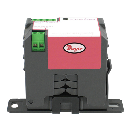
the Series SCS low Cost Current Switches are ideal for monitoring whether
fans, pumps, or motors are operating. The current flowing through the core of the
device powers the circuit without an external power supply. All models have a built in
solid state output and are easy to install. Optional LED's and 10 Amp relay modules
are available. The Series SCS is available in both Split and Solid Core configurations.
notICE
The Series SCS Current Switches are intended to provide an input to equipment
under normal operating conditions. Where failure or malfunction of the current switch
could lead to personal injury or property damage to the controlled equipment or other
property, additional precautions must be designed into the control system.
Incorporate and maintain other devices such as supervisory or alarm systems or
safety or limit controls intended to warn of, or protect against, failure or malfunction
of the SCS.
Caution: Risk of Shock
Disconnect power supply before making electrical connections. Contact
with components carrying hazardous voltage can cause electrical shock
and may result in severe personal injury or death.
InStallatIon
MoUntInG
1.
Detach the plastic mounting bracket from the current switch housing.
2.
Using the two included screws, attach the mounting bracket to the
rear of the electrical panel or enclosure.
3.
Re-attach the current switch housing to the plastic mounting bracket.
WIRInG (See figures 1 through 4 for examples of wiring)
1.
Disconnect the power to the conductor cable from the power source.
2a.
For solid core devices, slide the power conductor cable through the
sensing hole of the current switch.
2b.
For split core devices, open the core using the release tab. Snap the
core closed around the power conductor cable. Make sure that the
core release tab is locked in its original position.
3.
Wire the Series SCS output terminals to the control box Digital Input
(DI) terminal (30 V max. terminal voltage). For snap-on relay models,
see figures 3 and 4 for wiring information.
4.
Reconnect the power conductor cable.
DWYER InStRUMEntS, InC.
P.o. BoX 373 • MICHIGan CItY, InDIana 46361, U.S.a.
Series SCS Current Switches
Specifications - Installation and operating Instructions
2-45/64
[68.6]
SCS-220015, SCS-220150, AND SCS-211125
POWER
SOURCE
1-27/32
63/64
[47.0]
[24.9]
2-35/64
[64.5]
1-5/64
[27.4]
MODELS
SCS-111100 AND SCS-120025
2-9/16
1-1/16
[65.0]
[26.9]
MODELS
SPECIFICatIonS
output: Isolated, normally open.
External Relay: SPST N.O., 10A at 260 VAC (5A at 30 VDC).
Power Requirements: None, self-powered.
temperature limits: 5 to 140°F (-15 to 60°C).
Isolation Voltage: 600 VAC RMS.
Frequency: 50/60 Hz.
Enclosure rating: UL, V-O flammability rated, ABS plastic housing (solid core) or
Type 66 Nylon (split core).
agency approval: UL, CE.
BUILDING AUTOMATION
CONTROLLER
DI
DI
FAN OR
PUMP
HEATING ELEMENT
FIGURE 1
CONTROL POWER
CONTROLLER
DI
DO
RELAY COIL
24 V AC/DC
Phone: 219/879-8000
Fax: 219/872-9057
Bulletin PC-1-SCS
2-9/16
1-9/16
[65.0]
[39.6]
2-35/64
[64.5]
1-5/64
[27.4]
MODELS
SCS-111100-R
2-9/16
1-1/16
[65.0]
[26.9]
2-45/64
[68.6]
MODELS
SCS-220150-R AND SCS-211125-R
CONTACTOR
FAN OR PUMP
MOTOR
FIGURE 2
CONTACTOR
FAN OR PUMP
POWER
FIGURE 3
www.dwyer-inst.com
e-mail: info@dwyer-inst.com
CONTROLLER
DI
Advertisement

Subscribe to Our Youtube Channel
Related Manuals for Dwyer Instruments SCS Series


Summary of Contents for Dwyer Instruments SCS Series
- Page 1 (DI) terminal (30 V max. terminal voltage). For snap-on relay models, see figures 3 and 4 for wiring information. Reconnect the power conductor cable. FAN OR PUMP POWER FIGURE 3 DWYER InStRUMEntS, InC. Phone: 219/879-8000 www.dwyer-inst.com P.o. BoX 373 • MICHIGan CItY, InDIana 46361, U.S.a. Fax: 219/872-9057 e-mail: info@dwyer-inst.com...
- Page 2 Status): 1. Turn the setpoint screw clockwise until the Status Closed Light-Emitting Diode (LED) turns off and the Status Open LED turns on. ©Copyright 2018 Dwyer Instruments, Inc. FR# 443696-00 Rev. 1 DWYER InStRUMEntS, InC. Phone: 219/879-8000 www.dwyer-inst.com...
Need help?
Do you have a question about the SCS Series and is the answer not in the manual?
Questions and answers