Advertisement
Quick Links
Installation and mounting manual for EK-FC580 GTX water block
This product is intended for installation only by expert users. Please consult with a qualified technician for installation. Improper installation may result in damage to your equipment. EK Water Blocks assumes no liability
whatsoever, expressed or implied, for the use of these products, nor their installation. The following instructions are subject to change without notice. Please visit our web site at
Before installation of this product please read important notice, disclosure and warranty conditions printed on the back of the box.
The barb hose fittings require only a small amount of force to screw them in; otherwise the high flow fittings might break. These fittings do not need to be tightened with much force because the
liquid seal is made using o-rings.
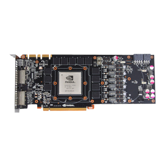
STEP 1: GENERAL INFORMATION. Sample picture of NVidia GeForce 580 GTX graphic card.
STEP 2 cont.: PREPARING YOUR GRAPHIC CARD
1 cont.. REMOVING STOCK COOLER.
screws and backplate should be removed. There are 20 screws on the back of the graphic
card.
3. APPLYING THERMAL COMPOUND. Apply thermal compound: lightly coat
both GPUs and bridge chip with electrically non-conductive thermal interface
material (TIM) - for example: Arctic Cooling MX-2™ or MX-4™ thermal
grease. EKWB recommends to apply thermal grease in cross form for best
performance (see sample picture).
STEP 3: INSTALLING WATER BLOCK
1. PLACING THERMAL PADS ON PCB. Place thermal pads on chips so that numbers on chips
match size of thermal pads. Thermal pad number 1, 2, 3 and 4 will have to be cut by user to
match all small power regulation chips (EKWB made sure users have more than enough
pads to cover all surfaces that need to be covered to make block fully functional). You can
also use small drop of thermal grease on chips to make thermal pads more adhesive.
1 1 1
1
1
1
All disclosures, notices and warranty conditions are being written on the back of the box.
Remove all encircled screws. All heat sink assembly
1
4
3
1
1
1
2
3
1
1
2. CLEANING THE PCB. Carefully detach the original heat sink after removing all
fasteners securing it to the board and bracket. Wipe off the remains (by using
non–abrasive cloth or Q-tip, as shown on sample photo) of the original thermal
compound until the components and circuit board are completely clean. EKWB
does not recommend using any liquids for removing paste.
4. CUTTING THERMAL PADS. Your block comes with thermal pads, which have to be placed on
chips (PLEASE REMOVE FOIL ON BOTH SIDES OF THERMAL PADS PRIOR TO INSTALLATION.
WARNING: DIMENSION BELLOW ARE SCALED.)
All thermal pads need to be cut to pieces of appropriate size to fit onto RAM chips (pad #1),
R125 inductors (pad #2), R33 inductors (pad #4), MOSFET chips and IC drivers (pad #3).
2. PLACING GPU REINFORCE PLATE ON PCB. Place metal reinforce and washer on
PCB as shown on picture below and screw it in with enclosed M3x4 screws. Please
use encased PVC washers under each screw. Make sure you use fasten screws
equally and do not use too much force.
Orientation
of reinforcer
is important!
PVC washer
www.ekwaterblocks.com
STEP 2: PREPARING YOUR GRAPHIC CARD.
1. REMOVING STOCK COOLER: Remove encircled
screws on the bracket:
th
Released on 16
of November, 2010. Revision 1.0
for updates.
Washer
M3x4
screw
Advertisement

Related Manuals for ekwb EK-FC580 GTX


Summary of Contents for ekwb EK-FC580 GTX
- Page 1 PCB as shown on picture below and screw it in with enclosed M3x4 screws. Please match all small power regulation chips (EKWB made sure users have more than enough use encased PVC washers under each screw. Make sure you use fasten screws pads to cover all surfaces that need to be covered to make block fully functional).
- Page 2 Use 6mm Allen key to screw in and tighten new EK-Plug G1/4. Attach the liquid cooling tension on the PCI-express slot. Tighten the screw with Philips screwdriver tubes and connect the water-block(s) into the cooling circuit. EKWB recommends using high flow while holding the M3 nut with your thumbs firmly.
Need help?
Do you have a question about the EK-FC580 GTX and is the answer not in the manual?
Questions and answers