
Related Manuals for Omega FMG490 Series


Summary of Contents for Omega FMG490 Series
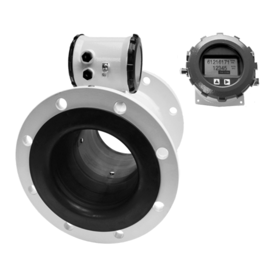
- Page 1 User’s Guide Shop online at omega.com e-mail: info@omega.com For latest product manuals: omega.com/en-us/pdf-manuals XXXXXX FMG490 SERIES Xxxxx Xxxxxxxx Municipal/Industrial Magmeter...
- Page 2 Fax: (203) 359-7700 e-mail: info@omega.com For Other Locations Visit omega.com/worldwide The information contained in this document is believed to be correct, but OMEGA accepts no liability for any errors it contains, and reserves Page 2 the right to alter specifications without notice.
-
Page 3: Table Of Contents
TABLE OF CONTENTS FMG490 INSTRUCTIONS General Information General Information ..............................Page 4 Features ...................................Page 4 Specifications ................................Page 5 Dimensions ..................................Page 6 Accuracy ..................................Page 7 Flow Rate ..................................Page 7 Installation Straight Pipe Recommendations ...........................Page 8 Full Pipe Recommendations ............................Page 9 Positioning the Meter ..............................Page 10 Installing Gaskets ................................Page 10 Tightening Flange Bolts ..............................Page 11 Equalization and Grounding (Metal and Plastic Pipe) ..................Page 11... -
Page 4: General Information
Minimal straight pipe requirements allow FMG490 The FMG490 Series is CE certified and IP68 for burial, or meters to be used in piping configurations where there is applications where the meter may be under water for little space between the meter and an elbow. -
Page 5: Specifications
GENERIAL INFORMATION FMG490 INSTRUCTIONS Specifications* Pipe Sizes 3”, 4”, 6”, 8”, 10”, 12” Flanges 150 lb. ANSI Pattern Pressure 150 psi (10.3 bar) line pressure Temperature Operating 10˚ to 140˚ F (-12˚ to 60˚ C) Storage -40˚ to 158˚ F (-40˚ to 70˚ C) Accuracy ±0.75% of reading on FMG480 and FMG490 (±1.0% FMG470), ±0.025% of full-scale flow from low flow cutoff to maximum flow rate of 10 m/sec... -
Page 6: Dimensions
GENERAL INFORMATION FMG490 INSTRUCTIONS Dimensions Remote Display 6.840” (173.7 mm) 4.000” (101.6 mm) 4.150” (105.4 mm) 3.500” (88.9 mm) 5.200” (132.1 mm) 4.375” (111.1 mm) Ø 5.285” (134.2 mm) Ø 0.200” (5.08 mm) Remote Meter FMG490 Shipping Weight Meter Size inch inch inch inch 3”* 12.25 7.08 179.8 17.25 66.04 4”... -
Page 7: Flow Rate
GENERAL INFORMATION FMG490 INSTRUCTIONS FMG490 Accuracy (m/s) (ft/s) Flow Velocity Flow Rate (3” - 12”) Pipe Size 3” 4” 6” 8” 10” 12” (Inches in diameter) Max Flow Rate 1285 2891 5140 8031 11565 (Gallons/Minute) Cut-off (min) Flow 3.62 6.43 14.46 25.70 40.15 57.82 Rate... -
Page 8: Installation
INSTALLATION FMG490 INSTRUCTIONS Straight Pipe Recommendations (X = diameter) NOTE: These configurations are to be used as general guidelines and do not cover every possible installation. A combination of two or more obstructions will require additional straight pipe. If there is any concern about the length of pipe required for a specific application, please contact your local dealer. -
Page 9: Full Pipe Recommendations
INSTALLATION FMG490 INSTRUCTIONS Full Pipe Recommendations Recommended: Not Ideal: Keep pipe full at meter for accuracy Allows air pockets to form at meter 12345 12345 12345 Recommended: Not Ideal: Keeps pipe full at meter for accuracy Post-valve cavitation can create air pocket Recommended: Not Ideal: Allows air to bleed off... -
Page 10: Positioning The Meter
INSTALLATION FMG490 INSTRUCTIONS Positioning the Meter Installing Gaskets CAUTION: These flow sensors are not recommended where installation may GASKETS Gaskets are required at all expose the flow sensor to boiler pressure junctions. and temperature. Maximum recommended operating temperature is 130˚ F. These meters can be installed horizontally, vertically (with 1. -
Page 11: Tightening Flange Bolts
INSTALLATION FMG490 INSTRUCTIONS Tightening Flange Bolts Equalization and Grounding NOTE: Mating pipe flanges must be ANSI 150# full face (FF) WARNING: ELECTRICAL SHOCK HAZARD and/or raised face (RT). When the FMG490 is installed in a plastic piping system, or when externally powered, 1. -
Page 12: Connections
CONNECTIONS FMG490 INSTRUCTIONS General Cable Information For the FMG490, a cable needs to be installed from the The display is available in either DC or AC versions. terminal block on the remote display interface board to the 15 pin connector inside the remote display. This cable is referred to as the remote meter cable. -
Page 13: Cable Installation
CONNECTIONS FMG490 INSTRUCTIONS Cable Installation Remote Display Wiring 10. Remove the plug and o-ring from the AC cable port. 1. On the remote display, unscrew the display lid and 11. Install cable gland and insert cable end. remove it. 12. Strip cable jacket and conductors and install 3 2. - Page 14 CONNECTIONS FMG490 INSTRUCTIONS Cable Installation Remote Meter Wiring 6. Secure the remote sensor cable inside the internal strain relief clip and tighten the cable gland sealing 1. On the remote meter, unscrew the user access lid nut securely (torque strain relief/sealing gland and remove it.
-
Page 15: Wiring Diagrams
CONNECTIONS FMG490 INSTRUCTIONS Wiring Diagrams (Remote Display) Remove the 3 screws holding the display assembly and remove it from the meter. Remove the 15 pin screw connector from its bag. Install the wires through the cable glands into the 15 pin screw connector in their respective locations. Plug the 15 pin screw connector into its socket. -
Page 16: Cable Wiring Table
CONNECTIONS FMG490 INSTRUCTIONS Cable Wiring Table ISO- -REM +REM PULSE PULSE O ID PWR+ PWR- B/RX A/TX VISO 4-20 - 4-20 + SCLD+ SCLD- D5N/ BLACK BLUE ORNG BLACK GREEN WHITE D5L/ BLACK BLUE ORNG BLACK BLUE ORNG GREEN WHITE A5N/ BLACK BLUE... -
Page 17: Configuration
FMG490 INSTRUCTIONS CONFIGURATION Pulse or Digital Output Application - Sourcing Mode (Recommended for Rin < 30kΩ) Pulse or Digital Output Application - Sinking Mode (Recommended for Rin > 30kΩ) Analog (4-20mA Current Loop) Output Application ** Minimum resistor value is (100 x Vs) ohms. Higher resistances maybe used depending on frequency and cable length. Longer cables and high frequencies require lower resistance. *** Resistor RL converts 4-20mA current to voltage for voltage input only devices. Page 17... -
Page 18: Cable Shield
CONFIGURATION FMG490 INSTRUCTIONS Cable Shield. In general, the cable shield and its bare drain Flow Rate at wire should be left unconnected at the user equipment end of Flow Rate at 150 Hz (GPM) Flow Rate at 1 200 Hz (GPM) Battery Powered the cable to minimize “ground loop”... -
Page 19: Operation
OPERATION FMG490 INSTRUCTIONS Changing Flow Meter Settings Home Screen and General Navigation Making Selections Once in the Menu System, move from tab to The HOME Screen displays flow volume, direction of the flow total and flow RATE along with status conditions such tab by tapping the right button. - Page 20 OPERATION FMG490 INSTRUCTIONS Standard Menu Options Note: Available options will depend on specific meter configuration. Not all options are available on all meters. Options not ordered with your meter will not appear on the meter menu. T UNIT SET 4 T UNIT R UNIT SET P DAMP...
-
Page 21: To Change A Passcode
OPERATION FMG490 INSTRUCTIONS To Change a Passcode and Decimal Places The FMG490 has a passcode system for restricting access PDAMP to the menus. The meter comes from the factory with the PDAMP is used to view or change the number of samples passcode set to 000000. -
Page 22: Troubleshooting & Error Messages
TROUBLESHOOTING & ERROR MESSAGES FMG490 INSTRUCTIONS Troubleshooting Troubleshooting Problem Probable Causes Things to try… Blank Display Faulty wiring from power source to Check for incorrect wiring. Measure voltage with meter DMM where red and black wires connect to terminal block TB1 on back side of display. Verify correct polarity and confirm that voltage is steady and between 9Vdc and 32Vdc Backup battery has not been plugged in... - Page 23 Department will issue an Authorized Return (AR) number immediately upon phone or written request. Upon examination by OMEGA, if the unit is found to be defective, it will be repaired or replaced at no charge. OMEGA’s WARRANTY does not apply to defects resulting from any action of the purchaser, including but not limited to mishandling, improper interfacing, operation outside of design limits, improper repair, or unauthorized modification.
- Page 24 FMG490 INSTRUCTIONS Where Do I Find Everything I Need for Process Measurement and Control? OMEGA…Of Course! Shop online at omega.com TEMPERATURE Thermocouple, RTD & Thermistor Probes, Connectors, Panels & Assemblies Wire: Thermocouple, RTD & Thermistor Calibrators & Ice Point References Recorders, Controllers &...
Need help?
Do you have a question about the FMG490 Series and is the answer not in the manual?
Questions and answers