Table of Contents
Advertisement
Quick Links
Advertisement
Table of Contents

Related Manuals for Siemens 7XV5450-0 A00 Series


Summary of Contents for Siemens 7XV5450-0 A00 Series
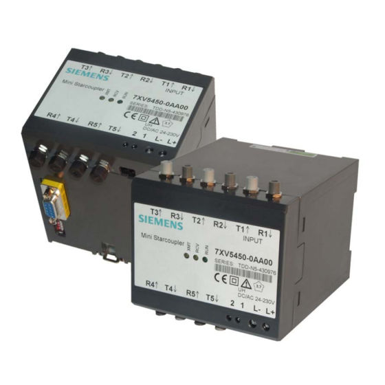
- Page 1 Mini-Starcoupler 7XV5450-0xA00 Operating Instructions Oct. 2006...
-
Page 2: Table Of Contents
Table of content GENERAL INSTRUCTIONS ......................3 Qualified Personnel ........................4 Safety Notes ..........................5 Intended Use ..........................6 Explanation of the symbols at the device:...................6 Exclusion of liability ........................7 Copyright .............................7 1 OPERATING INSTRUCTIONS ....................8 1.1 Scope of Application......................8 Technical Features........................8 General Data ..........................8 Data Transfer..........................9 Connection to a PC with Serial Interface ..................10 FO-Connections ........................10... -
Page 3: General Instructions
If further information is desired or in case special problems should arise, which are not treated adequately in this document, it is possible to obtain additional details from the local Siemens office or from the addresses stated in the back of this manual. -
Page 4: Qualified Personnel
Qualified Personnel Tampering with the device/system or noncompliance with the safety notices given in this manual may cause severe bodily injury or property damage. Therefore any interventions on the device/system may only be performed by adequately qualified personnel. Qualified personnel as per the safety notices given in these instructions or on the product itself is: •... -
Page 5: Safety Notes
Safety Notes These operating instructions contain notes that are to be complied with for your personal safety as well as to avoid property damages. These notes are marked by a triangular warning symbol and the different degrees of danger are categorized as follows: Danger Disregard of the corresponding precautionary measures will cause death, severe bodiliy injury or... -
Page 6: Intended Use
Siemens. Faultless and safe operation of the product require proper transport, storage, mounting and installation as well as careful operation and maintenance. -
Page 7: Exclusion Of Liability
Necessary corrections will be included in the next edition. You are invited to send us your suggestions for improvement. Copyright Copyright Siemens AG 2000. All rights reserved. Transmission or reproduction of this document, as well as the use and forwarding of its contents is not permitted without express written authority. -
Page 8: 1 Operating Instructions
1 Operating Instructions 1.1 Scope of Application The Mini Star Coupler is used for optical connection of up to four terminal units with an optical interface in a star topology to a master unit for centralized operation, thus allowing to establish an inter-ference- immune connection between the field devices and the centralized operating unit. -
Page 9: Data Transfer
coupler is possible. The Mini-Starcoupler has a plastic housing that can be snapped onto a DIN EN 50022 rail. The auxiliary power supply is fed in via terminals on one side of the housing. Because of its extremely wide auxiliary voltage range (DC 24 - 250 V and AC 60 - 250 V), the Starcoupler can be connected without switchover to all common types of station batteries and AC mains voltage supplies. -
Page 10: Connection To A Pc With Serial Interface
Connection to a PC with Serial Interface For central remote, the serial interface of the star coupler can be connected to a PC by means of a serial cable. Pins 7 and 8 of this cable must be jumpered. (Note that this deactivates FO Input channel 1). The serial interface distributes data to the four FO channels and receives data from these channels. -
Page 11: Technical Datas
Technical datas 3.1 Hardware features Mechanical design Housing Plastic, EG90 Dimensions see dimensional drawings Weight approx. 250g Degree of protection according EN60529, IEC60529 Housing IP 51 plasic Terminals IP 20 Auxiliary voltage U Rated input voltage 24 V - 250 V DC ± 20 % - DC voltage 24 V - 230 V AC ±... -
Page 12: Safety Tests
Optical interfaces Optical inputs / outputs 5 transmitter, 5 receiver Factory setting: Light OFF in idle state Optical connectors BFOC-ST connectors Laser class 1 acc. EN60825-1/-2 (plastic protective caps) Data flow indication Yellow LED: Transceiving data on Input channel 1 Wave length 820 nm Launched power... -
Page 13: Dielectric Tests
3.3 Dielectric Tests Dielectric tests EN61010 IEC 255-5: ANSI/IEEE C37.90.0 Voltage test (routine test) 5,25 kV DC / 1s (with bypass Auxiliary power to fault relay capacitors) Auxiliary power to RS232 3,7 kV AC / 50Hz / 1s (without interface bypass capacitors) Fault relay to RS232 interface 5 kV (peak);... -
Page 14: Interference Immunity
3.5 Interference immunity Interference immunity IEC 255-22 (product standards) EN 61010-1 (Generic standard) High frequency test 1 MHz; 400 surges per s; dur. 2 s IEC 60255-22-1, class III 2,5 kV longit.voltage; VDE 0435 Teil 303, Klasse III 1,0 kV transverse voltage Electrostatic discharge (ESD) 4 kV contact discharge, IEC 61000-4-2, class III... -
Page 15: Climatic Stress Tests
Fast transient disturbance / burst On signal lines IEC 61000-4-4, Klasse III 2 kV; 5/50 ns; 5 kHz; burst duration 15 ms IEC 60255-22-4, Klasse III Repetition 300 ms; both polarities; EN 61000-4-4, Klasse III Ri = 50 Ohm; Test duration 1 min Line contucted HF, amplitude 10 V;... -
Page 16: Mechanical Stress Tests
3.7 Mechanical Stress Tests Vibration and shock during operation sinusoidal 10 Hz to 60 Hz: Vibration ±0,035mm IEC 60255-21-1, class 1 IEC 60068-2-6 amplitude.; 60Hz - 150 Hz: 0,5g acceleration Frequency sweep rate 10 oktave/min 20 cycles in 3 orthogonal axes, Shock semi-sinusoidal IEC 60255-21-2, class 1... -
Page 17: Dimension Drawings
Dimension Drawings 7XV5450-0AA00 Mini-Starcoupler SERIES: A4-K7-655430 24-250V DC 60-230V AC N/L- L1/L+ Fig. 1: Dimension Drawings Ordering Data Name Order-No. Mini-Starcoupler 7 X V 5 4 5 0 - 0 A 0 0 with 1 FO-Interface (input) and 4 FO-Interface (output) and 1 RS232-Interface Optical In- / Output BFOC-ST connector... -
Page 18: Description Of The Functional Unit
Description of the Functional Unit The housed signal converter is a hard-wired and tested functional unit. It is provided with a snap-on mounting device for a 35 mm DIN EN 50022 rail and with screw-type terminals for safe connection of the auxiliary power supply. -
Page 19: Screw-Type Terminals X2, X7
Screw-type terminals X2, X7 Assignment Symbol X2, Pin 1 Power supply pin 1 (L+) DC: L+ AC: L X2, Pin 2 Power supply pin 2 (L-) DC: L- AC: N X7, Pin 1 Relay contact pin 1 X7, Pin 2 Relay contact pin 2 Tab. -
Page 20: Fo-Connections
FO-Connections The receiving optical connectors are marked with Rx, the transmitting connections with Tx. Switch positions The DIP switches can be actuated from outside. For standard applications the mini star coupler can directly be applied with its factory pre-settings, i.e: •... -
Page 21: Assignment Switch 1
Assignment Switch 1 Schalter Stellung Bedeutung open Star cascade connection closed Ring cascade connection open RS232 interface blocked closed RS232 interface can be actived by cable e.g. 7XV5100-4 open Not connected closed open Light ON in idle state Channel 4 closed Light OFF in idle state Channel 4 open... -
Page 22: Installation And Commissioning
Installation and Commissioning Warning When operating electrical devices, certain parts are necessarily under dangerous voltage. Therefore, disregard of the operating notes may cause servere bodily injury or property damage. Installation and electrical connection of the device should be performed by adequately qualified personnel only. -
Page 23: Power Supply X2
5.2.1 Power supply X2 The wires for the auxilliary voltage are screwed on terminal X2 at he bottom side of the device. The assignment of the terminals is printed at the front side or can be read in this manual. Because the device has no ON/OFF switch this switch must be installed external if it´s necessary. -
Page 24: Commissioning
Commissioning • Clip the signal converter on the top–hat rail according EN 50022 with the help of clip-on mounting. Do not make any changes at the device. • Check whether the operation data comply with the values on the rating plate. Not change any DIP-switch at the device, before reading this manual. -
Page 25: Application Examples
Application examples Optical star configuration Several mini-star couplers can be cascaded in the star configuration, to interface with further addressable protection devices. This star configuration can be extended with the corresponding converter to also include a RS485 bus structure (see manual 7XV5650). 19.10.2006 Mini-Starcoupler Page 25 of 28... -
Page 26: Optical Ring Configuration
Optical ring configuration Several mini star couplers can be cascaded in the ring configuration. The transmitter channel 1 must be connected with the receiver channel1 in the next mini star coupler, and then back to the pc/modem. In this manner a ring configuration is created, whereby one additional output per mini star coupler to a protection device is available Attention! The data from the pc are mirrored back to the pc or modem. - Page 27 EG-Konformitätserklärung EC Declaration of Conformity No E471015-3 Siemens Aktiengesellschaft Hersteller: Manufacturer: Bereich Anlagenbau und Technische Dienstleistungen ATD Technische Dienstleistungen TD Siemensstraße 33 Anschrift: Address: D - 71254 Ditzingen Bundesrepublik Deutschland Produkt- Mini-Sternkoppler bezeichnung: Product 7XV5450-0xA00 description Mini-Starcoupler Das bezeichnete Produkt stimmt in der von uns in Verkehr gebrachten Ausführung mit den Vorschriften folgender Europäischer Richtlinien überein:...
- Page 28 If you have any notes or questions on this product please contact us under the following address: Siemens AG Power Transmission and Distribution Power Automation Depart. PTD PA 13 Postfach 4806 D-90026 Nürnberg Telefax (+49 911) 433-8301 Further informations regarding our products in the INTERNET under: http://www.SIPROTEC.com.
Need help?
Do you have a question about the 7XV5450-0 A00 Series and is the answer not in the manual?
Questions and answers