
Related Manuals for IFM Electronic efector 500 PM2055


Summary of Contents for IFM Electronic efector 500 PM2055
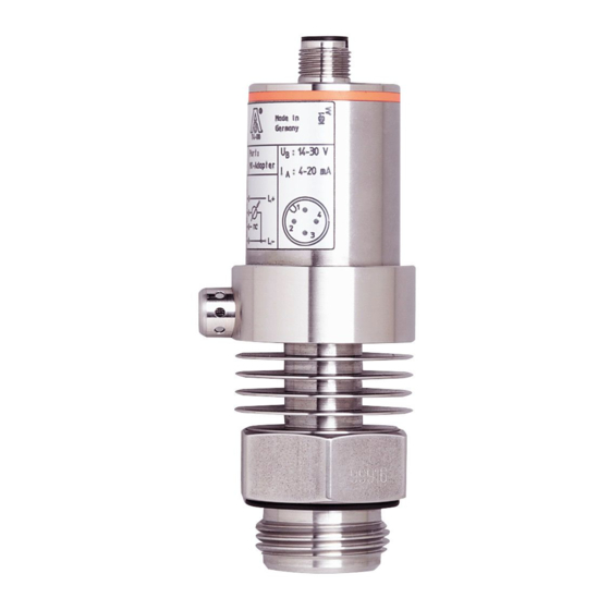
- Page 1 Bedienungsanleitung Operating instructions Notice utilisateurs Elektronischer Drucksensor Electronic pressure sensor Capteur de pression électronique PM2055...
-
Page 2: Table Of Contents
Inhalt 1 Bestimmungsgemäße Verwendung ... . . Seite 3 2 Verwendung im Auslieferungszustand ..Seite 4 Montage ........Seite 4 Elektrischer Anschluß... -
Page 3: Bestimmungsgemäße Verwendung
Sicherheitshinweise Lesen Sie vor der Inbetriebnahme des Gerätes die Produktbeschreibung. Vergewissern Sie sich, daß sich das Produkt uneingeschränkt für die betreffende Applikationen eignet. Die Mißachtung von Anwendungshinweisen oder technischen Angaben kann zu Sach- und/oder Personenschäden führen. Prüfen Sie in allen Applikationen die Verträglichkeit der Produktwerkstoffe (s. -
Page 4: Verwendung Im Auslieferungszustand
Verwendung im Auslieferungszustand Montage Stellen Sie vor Ein- und Ausbau des Sensors sicher, daß die Anlage druckfrei ist. Durch Aseptoflex-Adapter ist der Sensor adaptierbar an unter- schiedliche Prozeßanschlüsse. (Adapter sind gesondert als Zubehör zu bestellen). Montieren zuerst Adapter (B) an den Sensor, dann Sensor + Adapter mit Hilfe einer Überwurfmutter, eines Klemm- flanschs o. - Page 5 Verwendung im Auslieferungszustand Schritt 2 Schrauben Sie den Sensor in den Adapter ein. Vermeiden Sie dabei mechanische Einwirkungen auf die Dichtflächen. Schritt 3 Spannen Sie Sensor + Adapter in eine Klemmvorrichtung (D). Die Dichtflächen (E) dürfen dabei nicht beschädigt werden. Ziehen Sie den Sensor mit einem Schraubenschlüssel an, bis der Anschlag spürbar ist.
-
Page 6: Inbetriebnahme / Betrieb / Wartung
Verwendung im Auslieferungszustand Inbetriebnahme / Betrieb / Wartung Prüfen nach Montage, elektrischem Anschluß Programmierung, ob das Gerät sicher funktioniert. Reinigen der Filterabdeckung Sollten zähflüssige und rück- standbildende Medien Filterabdeckung Sensors zusetzen (und damit Meßgenauigkeit geringfügig beeinträchtigen), können Sie die Abdeckung reinigen. Schrauben Filter- abdeckung (B) ab (benutzen Sie... -
Page 7: Sensor Programmieren / Betrieb Mit Eps-Interface
Sensor programmieren / Betrieb mit EPS-Interface EPS-RS232-Interface Verbinden Sie den Sensor über das EPS-RS232-Interface (Bestell-Nr. E30066) mit einem PC. • Der Sensor wird vom Interface mit Betriebsspannung versorgt, • und überträgt über das Interface kontinuierlich seine Daten (Meßwerte, Analogsignal und Parameter-Einstellungen). Es bieten sich damit folgende Möglichkeiten: •... -
Page 8: Elektrischer Anschluß (Sensor - Eps-Interface)
Sensor programmieren / Betrieb mit EPS-Interface Elektrischer Anschluß von Sensor und EPS-RS232-Interface Wenn Sie Sensor und Interface außerhalb der Anlage betreiben: Verwenden Sie zur Spannungsversorgung ein geeignetes Netzgerät (z. B. 24 V Power Supply, Bestell-Nr. E30080). Wenn Sie das Interface in der laufenden Anlage verwenden: Schalten Sie die Anlage spannungsfrei bevor Sie das Gerät anschließen. -
Page 9: Technik-Information / Funktionsweise / Parameter
Technik-Information / Parameter / Funktionsweise Einstellbare Parameter Analogstartpunkt Meßwert, bei dem 4 mA ausgegeben werden. Analogendpunkt Meßwert, bei dem 20 mA ausgegeben werden. Mindestabstand zwischen ASP und AEP = 25% der Meßspanne Einstellbereiche: in Schritten von -0,99 ... 1,00 0,26 ... 4,00 0,01 -14,4 ... -
Page 10: Technische Daten
4 Technik-Information / Parameter / Funktionsweise Einstellbare Parameter (Fortsetzung) Einstellung der Anzeige d1 / d2 / d3 = Meßwertaktualisierung alle 50 ms / 200 ms / 600 ms. Die Meßwertaktualisierung betrifft nur die Anzeige. Ph = kurzeitig festgehaltene Anzeige des Spitzen-Meßwerts (peak hold). -
Page 11: Skalieren Des Meßbereichs
Technik-Information / Parameter / Funktionsweise Skalieren des Meßbereichs • Mit dem Parameter Analogstartpunkt (ASP) legen Sie fest, bei wel- chem Meßwert das Ausgangssignal 4 mA beträgt. • Mit dem Parameter Analogendpunkt (AEP) legen Sie fest, bei wel- chem Meßwert das Ausgangssignal 20 mA beträgt. •... - Page 12 Contents 1 Function and features ..... . page 13 2 Use with factory setting ....page 14 Installation .
-
Page 13: Function And Features
Safety instructions Read the product description before installing the unit. Ensure that the product is suitable for your application without any restrictions. Non-adherence to the operating instructions or technical data can lead to personal injury and/or damage to property. In all applications check compliance of the product materials (see Technical data) with the media to be measured. -
Page 14: Use With Factory Setting
Use with factory setting Installation Before mounting and removing the sensor, make sure that no pressure is applied to the system. The unit is adaptable for various process fittings by Aseptoflex adapters (to be ordered sepa- rately as accessories). Mount adapter (B) to the sensor first, then sensor + adapter to the process connection by means of a nut, a clamping flange or... -
Page 15: Electrical Connection
Use with factory setting Step 2 Screw the sensor into the adapter. Avoid mechanical influ- ence on the sealing chamfers. Step 3 Clamp sensor and adapter into a clamping device (D). The sealing chamfers (E) must not be dam- aged. Tighten the sensor with a spanner until you can feel the end stop. -
Page 16: Installation And Set-Up / Operation / Maintenance
Use with factory setting Installation and set-up / operation / maintenance After mounting, wiring and setting check whether the unit operates correctly. Cleaning of the filter cover If viscous and residues producing media clog the filter cover of the sensor (and thus reduce the mea- suring accuracy slightly), you can clean it. -
Page 17: Programming / Use With Eps Interface
Programming / Use with EPS RS232 interface EPS RS232 interface Connect the sensor to a PC via the EPS-RS232 interface (order no. E30066). • The sensor is supplied with operating voltage by the interface, • and transmits its data (measured values, analogue signal and para- meter settings) continuously via the interface. -
Page 18: Electrical Connection (Sensor - Eps Interface)
3 Programming / Use with EPS RS232 interface Wiring of sensor and EPS interface For use of the sensor with EPS interface prior to installation of the sen- sor: Use a suitable power supply (24 V power supply; ifm order no. E30080). -
Page 19: Technical Informations / Functioning / Parameters
Technical information / Functioning / Parameters Adjustable parameters Analogue start point Measured value at which 4 mA is provided. Analogue end point Measured value at which 20 mA is provided. Minimum distance between ASP and AEP = 25% of the span. Setting range: in steps of -0.99 ... -
Page 20: Technical Data
4 Technical information / Functioning / Parameters Adjustable parameters (continuation) Setting of the display d1 / d2 / d3 = update of the measured value every 50 ms / 200 ms / 600 ms. The update interval only refers to the display. ph = display of the measured peak value remains for a short time (peak hold);... -
Page 21: Scaling The Measuring Range
Technical information / Functioning / Parameters Scaling the measuring range • With the parameter "Analogue start point" (ASP) the measured value at which the output signal is 4 mA is defined. • With the parameter "Analogue end point" (AEP) the measured value at which the output signal is 20 mA is defined. - Page 22 Contenu 1 Fonctionnement et caractéristiques ... . page 23 2 Utilisation avec réglage usine ....page 24 Montage .
-
Page 23: Fonctionnement Et Caractéristiques
Remarque sur la sécurité Avant la mise en service de l'appareil, veuillez lire la descrip- tion du produit. Assurez-vous que le produit est approprié pour l'application concernée sans aucune restriction. Le non-respect des remarques ou des données techniques peut provoquer des dommages matériels et/ou corporels. Pour toutes les applications, veuillez vérifier la compatibilité... -
Page 24: Utilisation Avec Réglage Usine
Utilisation avec réglage usine Montage Avant de monter / démonter le capteur, s'assurer que la pression n'est pas appliquée au circuit. L'appareil est adaptable à diffé- rents types de raccords process par adaptateurs Aseptoflex (à commander séparément comme accessoires). Monter d'abord l'adaptateur (B) sur le capteur, ensuite le capteur et l'adaptateur sur le raccord pro- cess à... -
Page 25: Raccordement Électrique
Utilisation avec réglage usine Pas 2 Visser le capteur dans l'adapta- teur. Eviter des influences méca- niques sur les chanfreins d'étan- chéité. Pas 3 Serrer le capteur et l'adaptateur dans un dispositif de serrage (D). Les chanfreins d'étanchéité (E) ne doivent pas être endom- magés. -
Page 26: Mise En Service / Fonctionnement / Maintenance
2 Utilisation avec réglage usine Mise en service / Fonctionnement / Maintenance Après le montage, le câblage et le réglage vérifier le bon fonctionne- ment de l'appareil. Nettoyage du couvercle du système de filtrage Si des fluides visqueux qui pro- duisent des résidus bouchent le couvercle du système de filtrage du capteur (et donc réduisent... -
Page 27: Programmation / Capteur Avec Interface Eps-Rs232
Programmation / Capteur avec interface EPS-RS232 interface EPS-RS232 Raccorder le capteur à un PC via l'interface EPS-RS232 (n° de com- mande E30066). • Le capteur est alimenté en tension par l'interface • et transmet ses données (valeurs mesurées, signal analogique et paramètres réglés) continuellement via l'interface. -
Page 28: Raccordement Électrique (Capteur - Interface Eps)
3 Programmation / Capteur avec interface EPS-RS232 Raccordement électrique (capteur / interface EPS-RS232) Pour l'emploi du capteur avec interface EPS-RS232 hors de l'installa- tion: Utiliser une alimentation appropriée (alimentation 24 V; N commande E30080). Pour l'emploi mobile du interface EPS-RS232 sur une installation en service: Mettre l'installation hors tension avant de raccorder l'unité. -
Page 29: Informations Techniques / Fonctions / Paramètres
Informations techniques / Fonctions / Paramètres Paramètres réglables Valeur minimum de la sortie analogique Valeur mesurée dont le signal de sortie est 4 mA. Valeur maximum de la sortie analogique Valeur mesurée dont le signal de sortie est 20 mA. Ecart minimum entre ASP et AEP = 25% du gain. -
Page 30: Données Techniques
4 Informations techniques / Fonctions / Paramètres Paramètres réglables (continuation) Réglage de l'afficheur d1 / d2 / d3 = actualisation de la valeur mesurée toutes les 50 ms / 200 ms / 600 ms. L'actualisation ne change que l'intervalle d'actualisation de l'affichage. ph = affichage de la valeur maxi mesurée pour un bref délai (peak hold);... -
Page 31: Réglage De L'étendue De Mesure
Informations techniques / Fonctions / Paramètres Réglage de l'étendue de mesure • Par le paramètre "Valeur minimum de la sortie analogique" (ASP) on peut sélectionner la valeur mesurée à laquelle le signal de sortie est 4 mA. • Par le paramètre "Valeur maximum de la sortie analogique" (AEP) on peut sélectionner la valeur mesurée à... -
Page 32: Maßzeichnung
Maßzeichnung Scale drawing Dimensions M12 x1 1 Aseptoflex-Dichtkante 2 Aseptoflex-Gewinde 1 Aseptoflex sealing edge 2 Aseptoflex thread 1 chanfrein pour l'étanchéité Aseptoflex 2 filtetage Aseptoflex...
Need help?
Do you have a question about the efector 500 PM2055 and is the answer not in the manual?
Questions and answers