Table of Contents
Advertisement
Available languages
Available languages
Quick Links
S
DUAL BATTERY CHARGING SOLAR CONTROLLER
RÉGULATEUR DE CHARGE SOLAIRE POUR DEUX BATTERIES
POUR CAMPING-CARS, CARAVANES ET BATEAUX
FÜR WOHNMOBILE, WOHNWAGEN UND BOOTE
PARA VEHÍCULOS RECREATIVOS, AUTOCARAVANAS Y BARCOS
I
nstallatIon and
M
anuel d
B
edIenungs
M
anual de InstalacIón y operacIón
For a more detailed manual, please see our website.
Pour une version plus détaillée s'il vous plaît consulter notre site Web.
Für eine detailliertere Version finden Sie auf unserer Website.
Para obtener una versión más detallada por favor visite nuestro sitio web.
S
UN
AVER
S O L A R C O N T R O L L E R
FOR RVS, CARAVANS, AND BOATS
SOLARLADEREGLER FÜR ZWEI BATTERIEN
REGULADOR SOLAR DE CARGA DUAL
'
InstallatIon et d
-
I
und
nstallatIonsanleItung
www.morningstarcorp.com
D
o
peratIon
'
UO
TM
M
anual
utIlIsatIon
. . . 2
. . . 20
. . . 38
. . . 58
Advertisement
Table of Contents

Related Manuals for Morningstar SunSaver Duo


Summary of Contents for Morningstar SunSaver Duo
- Page 1 AVER S O L A R C O N T R O L L E R DUAL BATTERY CHARGING SOLAR CONTROLLER FOR RVS, CARAVANS, AND BOATS RÉGULATEUR DE CHARGE SOLAIRE POUR DEUX BATTERIES POUR CAMPING-CARS, CARAVANES ET BATEAUX SOLARLADEREGLER FÜR ZWEI BATTERIEN FÜR WOHNMOBILE, WOHNWAGEN UND BOOTE REGULADOR SOLAR DE CARGA DUAL PARA VEHÍCULOS RECREATIVOS, AUTOCARAVANAS Y BARCOS...
- Page 2 SUNSAVER DUO DIMENSIONS 6.65 168.78 6.10 154.94 2.17 1.00 55.12 25.4 0.28 7.24 1.36 34.52 inches (mm) Ratings • Nominal Voltage 12 Volts • Rated Solar Current 25 Amps...
-
Page 3: Important Safety Information
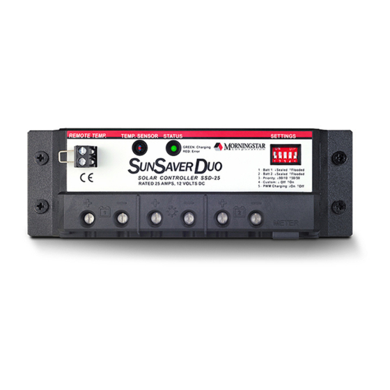
NOTE: Indicates a procedure or function that is important for the safe and proper operation of the controller. The major features of the SunSaver Duo are shown in figure 1 below. An explanation of The major features of the SunSaver Duo are shown in figure 1 below. -
Page 4: Morningstar Accessories
The MSC converts the MeterBus RJ-11 electrical interface to a standard RS-232 interface which allows communication between the SunSaver Duo and a PC. The MSC is required for programming custom charging setpoints and for logging data. Visit Morningstar’s website for more information. -
Page 5: General Installation Notes
• Only charge lead-acid batteries. • Each of the two SunSaver Duo Battery connections may be wired to one battery or a bank of batteries. The following instructions refer to a singular battery, but it shall be implied that each battery connection can be made to either one battery or a group of batteries wired in parallel to form a 12 volt battery bank. -
Page 6: Battery Type
DIP Switch 3 ON: 50% / 50% Priority DIP Switch 4 – Custom Setpoints If the standard battery type settings are not suitable, custom charging setpoints can be programmed using a PC and a Morningstar Serial to Meterbus adapter (not included). See Morningstar’s website for more information. -
Page 7: Risk Of Explosion
(flooded) batteries! Do not install in W A R N I N G : Never install the SunSaver Duo in a sealed enclosure with vented a confined area where battery gasses can accumulate. (flooded) batteries! Do not install in a confined area where battery gasses can RISK OF EXPLOSION! accumulate. - Page 8 RTS detection due to condensation on the SunSaver Duo. Do not remove this jumper unless an optional RTS is to be installed. R V / C A R A VA N I N STA LLA TI O N Figure 4.
- Page 9 (see page 17). Step 2: Battery #1 (“house” battery bank) Connect Battery #1 to the SunSaver Duo as shown in figure 4. In RV installations, Battery #1 should be the “house” or cabin battery.
- Page 10 Confirm that the solar modules are wired for 12V nominal output before connecting them to the SunSaver Duo. In full sun, the output voltage of the solar modules should be 18 – 25 Volts before connection to the SunSaver Duo.
- Page 11 5. Wire the “house” battery positive power cable as shown in terminal on the SunSaver Duo with black wire as shown in figure 5. Wire the figure 5. Wire a DC-rated in-line fuse holder in the cable. The length of “house”...
- Page 12 Connect the solar module(s) output to the Solar input connection of the SunSaver Duo. Multiple 12V nominal modules may be wired together in parallel and wired to the SunSaver Duo with one pair of wires. Use red wire for solar positive and black wire for solar negative.
- Page 13 Step 2: Battery #2 Connect Battery #2 to the SunSaver Duo as shown in figure 6. Use red wire for battery positive and black for battery negative. An in-line fuse holder should be wired in the positive line no further 12”...
-
Page 14: Operation
Step 5: Insert Fuses Insert a 30 A dc-rated fuse into the fuse holder in each of the battery positive wires. If the solar module(s) is in full sun, charging should begin. OPERATION LED Indications The Status LED indicates system operational state and any existing error conditions. -
Page 15: Charging Information
Pulse charging to restore full battery capacity. capacity. 3. Float – After battery is fully charged, SunSaver Duo reduces to a float 3. Float – After battery is fully charged, SunSaver Duo reduces to a float or “trickle or “trickle charge”. charge”. -
Page 16: Inspection And Maintenance
Charging automatically resumes when the problem is fixed. To resume operation without an RTS, disconnect all power to the SunSaver Duo and then reconnect. High Voltage Transients – Battery 1, Battery 2, and Solar input power connections are protected against high voltage transients. In lightning prone areas, additional external suppression is recommended. - Page 17 • Meterbus Connection ....6-pin RJ-11 • Transient Surge Protection ..1500 Watts, all power connections BATTERY CHARGING • Regulation Method ....... 300 Hz PWM or Slow Switching (10 Hz max.) • Temp. Compensation Coefficient .. –30 mV / °C (25°C reference) •...
- Page 18 One Way Wire Distance (feet) Solar Wire Gauge (AWG) Amps 3% Voltage drop, Annealed Copper Wire at 20°C One-way wire distance: Solar SunSaver Duo or SunSaver Duo Battery One Way Wire Distance (meters) Solar Wire Gauge (mm Amps 13.0...
- Page 20 DIMENSIONS DU SUNSAVER DUO 6.65 168.78 6.10 154.94 2.17 1.00 55.12 25.4 0.28 7.24 1.36 34.52 inches (mm) Ratings • Tension nominale 12 Volts • Courant solaire nominal 25 A...
-
Page 21: Informations De Sécurité Importantes
The major features of the SunSaver Duo are shown in figure 1 below. An explanation of Les éléments principaux du SunSaver Duo sont présentés dans la Figure each feature is provided. - Page 22 Bornes de sonde de température à distance (RTS) Point de raccordement d’une sonde Morningstar RTS (en option) pour contrôler à distance la température de la batterie. Sonde de température locale Mesure la température ambiante. Le courant de charge est régulé en conséquence.
-
Page 23: Réglage Des Commutateurs Dip
D I P Sw i t ches 1 & 2 – B at t er y Type Sel ect The SunSaver Duo charges both sealed and flooded lead-acid batteries per the charging specifications in table 1 below. Sealed batteries are typically... -
Page 24: Type De Batterie
Commutateur DIP 4 haut (ON) : Réglages programmés personnalisés Commutateur DIP 5 – Type de régulation Le SunSaver Duo est un régulateur de charge par modulation de largeur d’impulsion (PWM). Certains systèmes sensibles peuvent subir un brouil- lage causé par la charge PWM. Voir les conseils de réduction et d’élimination du bruit PWM dans la FAQ de la section 4.0 Dépannage. - Page 25 étanche avec des batteries non scellées (humides) ! W A R N I N G : Never install the SunSaver Duo in a sealed enclosure with vented Ne pas le poser dans un espace restreint où des gaz de (flooded) batteries! Do not install in a confined area where battery gasses can batterie peuvent s’accumuler.
- Page 26 N O TE: Wiring charts on the back page of this manual provide minimum empêcher une fausse détection par le capteur de température recommended wire size. à distance due à une condensation sur le SunSaver Duo. Ne pas déposer le cavalier, sauf en cas d’installation d’un capteur de température à distance en option.
- Page 27 Pose. Étape 1: Raccorder le SunSaver Duo à la terre Raccorder la borne négative du SunSaver Duo à la masse du véhicule. Le SunSaver Duo comporte un moins commun ; n’importe quelle borne négative peut être raccordée à la masse. Utiliser du fil à gaine noire de calibre correct pour le courant de charge (voir la dernière page).
- Page 28 à la terre au moyen d’un seul fil. Utiliser du fil rouge pour raccorder le pôle positif du circuit solaire au SunSaver Duo. Utiliser du fil de calibre correct pour le courant de charge (voir la dernière page).
- Page 29 Wire the negative terminal of the “house” battery to the negative Bat t er y 1 section Pose. terminal on the SunSaver Duo with black wire as shown in figure 5. Wire the Étape 1: Batterie 1 (groupe de batteries « habitation ») “house”...
- Page 30 Duo. Plusieurs modules de 12 V chacun peuvent être associés en paral- lèle et raccordés au SunSaver Duo au moyen d’une paire de fils. Utiliser un fil rouge pour le pôle positif et un fil noir pour le pôle négatif du cir- cuit solaire.
- Page 31 à la terre le cas échéant, au moyen d’un court fil noir Connect Battery #2 to the SunSaver Duo as shown in figure 6. Use red wire for de calibre correct pour le courant de charge (voir la dernière page).
- Page 32 Confirmer que les modules sont câblés de manière à fournir une tension nominale de 12 V avant de les raccorder au SunSaver Duo. Revérifier la polarité avant d’effectuer le branchement. En plein soleil, la tension de sortie des modules solaires doit être de 18 à 25 V avant raccordement au SunSaver Duo.
- Page 33 Chargement par impulsions pour rétablir la capacité maximale de la batterie. 3. Float – After battery is fully charged, SunSaver Duo reduces to a float or “trickle charge”. 3. Entretien – Une fois que la batterie est totalement chargée, le SunSaver Duo revient à...
-
Page 34: Contrôle Et Entretien
15 V permet de protéger les consommateurs DC sensibles. Protections Surintensité – Le courant de charge solaire dépasse l’intensité nominale du SunSaver Duo. Rétablissement automatique au bout de 30 secondes. ATTENTION : Le raccordement par erreur d’une batterie à l’entrée Solaire alors qu’une seconde batterie est déjà... -
Page 35: Caractéristiques Techniques
• Vérifier le bon serrage de tous les serre-câbles et attaches. • Vérifier que le régulateur est posé dans un milieu propre et protégé, à l’abri de la saleté, des insectes, des nids et de la corrosion. • Vérifier que la ventilation et les évents d’air du boîtier ne sont pas obstrués. -
Page 36: Caractéristiques Mécaniques
POINTS DE CONSIGNE DE BATTERIE Batterie scellée Humide • Absorption ........14,1 V 14,4 V • Entretien ........13,7 V 13,7 V • Durée avant entretien ....1 heure 1 heure • Égalisation ........néant 14,8 V • Calendrier d’égalisation ....néant 28 jours • Régulation maximum ....15,0 V 15,0 V •... - Page 37 Ampères (pieds) Solaires Calibre de Fil (AWG) Chute de tension de 3 %, fil de cuivre recuit à 20°C Distance de fil unidirectionnelle: Solaire SunSaver Duo ou SunSaver Duo Batterie Distance de Fil Unidirectionnelle (m) Ampères Solaires Calibre de Fil (mm 13.0...
- Page 38 ABMESSUNGEN SUNSAVER DUO 6.65 168.78 6.10 154.94 2.17 1.00 55.12 25.4 0.28 7.24 1.36 34.52 inches (mm) Nenndaten • Nennspannung 12 Volt • Solarnennstrom 25 Ampere...
- Page 39 Betrieb des Reglers von Bedeutung sind. The major features of the SunSaver Duo are shown in figure 1 below. An explanation of Die wichtigsten Funktionen des SunSaver Duo sind nachfolgend in each feature is provided.
-
Page 40: Allgemeine Hinweise Zur Installation
Adapter für PC-Meterbus (Modell: MSC) Mit dem MSC wird aus der RJ-11-Schnittstelle eine übliche RS-232- Schnittstelle, die die Kommunikation zwischen dem SunSaver Duo und einem PC ermöglicht. Der MSC wird für die Programmierung eigener Ladesollwerte und für Datenprotokolle benötigt. Weitere Informationen finden Sie auf der Internetseite von Morningstar. - Page 41 D I P Sw i t ches 1 & 2 – B at t er y Type Sel ect The SunSaver Duo charges both sealed and flooded lead-acid batteries per the charging specifications in table 1 below. Sealed batteries are typically maintenance-free batteries that do not require water.
- Page 42 DIP-Schalter 1 und 2 – Auswahl des Batterietyps Der SunSaver Duo lädt sowohl versiegelte als auch geflutete Bleibatterien gemäß den Angaben in der untenstehenden Tabelle 1. DIP-Schalter OFF: versiegelte Batterie (Werkseinstellung) DIP-Schalter ON: geflutete Batterie BATTERIETYP Einstellung Versiegelt Geflutet Spannung Dauerladung 14,1 V...
-
Page 43: Montage
Explosionsgefahr! W A R N I N G : Never install the SunSaver Duo in a sealed enclosure with vented (flooded) batteries! Do not install in a confined area where battery gasses can 1. Platzieren Sie den SunSaver Duo auf einer senkrechten Fläche, auf accumulate. - Page 44 INSTALLATION IM WOHNMOBIL/-WAGEN HINWEIS: Eine Drahtbrücke wird über die Temperatur- Fernfühler (RTS)-Terminals werkseitig installiert.Die Drahtbrücke kann falsche RTS-Erkennung aufgrund von Kondensation auf dem SunSaver Duo verhindern. Entfernen Sie diese Brücke nicht, es sei denn, ein optionaler RTS-Fühler soll installiert werden.
- Page 45 • verwenden Sie Kabelschuhe und Stern- bzw desired location. The SunSaver Duo should be mounted per the instructions in section Sicherungsscheiben zur Befestigung des Kabels. 2. 3 M ount i ng.
- Page 46 Schritt 3: Batterie 2 (für den Motor) Schließen Sie Batterie 2 wie in Abbildung 4 beschrieben an den SunSaver Duo an. Die Batterie für den Motor sollte bereits über das Fahrgestell geerdet sein. Verwenden Sie ein rotes Kabel für den Pluspol der Batterie.
- Page 47 The batteries must be secured to prevent movement and the battery terminals covered to prevent arcing. A battery box to contain any spilled battery acid is strongly recommended. The SunSaver Duo should be mounted per the instructions in section 2. 3...
- Page 48 Schritt 2: Batterie 2 („Haus“-Batterie) Verwenden Sie ein schwarzes Kabel, um den Minuspol der Batterie für den Motor mit dem Minuspol für Batterie 1 am SunSaver Duo (vgl. Abbildung 5) zu verbinden. Schließen Sie das Pluskabel der Batterie für den Motor gemäß Abbildung 5 an. Setzen Sie einen Gleichstrom- Sicherungshalter in das Kabel ein.
- Page 49 Schritt 1: Batterie 1 NOTE: If a Remote temperature Sensor (RTS) is not used, inserting a jumper the RTS terminals can prevent false RTS detection due to condensation SunSaver Duo. Secure a short piece of wire across the RTS terminals.
- Page 50 Schritt 2: Batterie 2 Verbinden Sie Batterie 2 wie in Abbildung 6 dargestellt mit dem SunSaver Duo. Verwenden Sie ein rotes Kabel für den Pluspol und ein schwarzes Kabel für den Minuspol der Batterie. Fügen Sie am Pluspol einen Sicherungshalter in einem Abstand von nicht mehr als 305 mm (12”) vom Batteriepol ein.
-
Page 52: Betrieb
Schritt 5: Einsetzen der Sicherungen Setzen Sie je eine 30-Ampere-Gleichstromsicherung in den Sicher- ungshalter des Kabels am Pluspol der beiden Batterien ein. Wenn das (die) Solarmodul(e) dem vollen Sonnenlicht ausgesetzt sind, sollte der Ladevorgang beginnen. BETRIEB LED-Anzeige Die LED-Statusanzeige zeigt den Betriebsstatus der Anlage und Fehler an. - Page 53 Pulse charging to restore full battery capacity. ein Überhitzen der Batterie und ein Austreten von Batteriegasen zu 3. Float – After battery is fully charged, SunSaver Duo reduces to a float or “trickle verhindern. Pulsladung zur Wiederherstellung der vollen charge”.
-
Page 54: Inspektion Und Wartung
Problem behoben ist, wird der Ladevorgang wieder aufgenommen. Um den Betrieb ohne einen RTS wieder aufzunehmen, trennen Sie den SunSaver Duo zunächst vollständig von der Stromversorgung und schließen ihn anschließend wieder an. Spannungsspitzen – Die Anschlüsse Batterie 1, Batterie 2 und Solareingang sind gegen Spannungsspitzen geschützt. -
Page 55: Technische Spezifikationen
TECHNISCHE SPEZIFIKATIONEN ELEKTRISCHE DATEN • Anlagennennspannung ....12 V • Max. Solarstrom ......25 A • Spannungsbereich der Batterie ... 1 V -15 V • Max. Solarspannung ..... 30 V • Eigenverbrauch ......5,5 mA (Nacht) 10,0 mA (Ladevorgang) • Genauigkeit Spannung ........1,0 % Strom ..........2,0 % •... - Page 56 • Lagerungstemperatur ......–40 °C bis +85 °C • Relative Luftfeuchtigkeit......100%, nicht kondensierend Empfohlene Mindestkabelstärke Kabellänge in Fuß (eine Strecke) Solar- Kabelstärke (AWG) ampere 3 % Spannungsabfall, Kupferdraht bei 20 C KWould abellänge (eine Strecke): Solar SunSaver Duo oder SunSaver Duo Batterie...
- Page 57 17,1 27,4 43,6 69,5 13,7 21,9 34,7 14,6 23,2 11,0 17,4 14,0 11,0 3 % Spannungsabfall, Kupferdraht bei 20 C Kabellänge (eine Strecke): Solar SunSaver Duo oder SunSaver Duo Batterie Änderungen vorbehalten. Entwickelt in den USA. Montiert in Taiwan.
- Page 58 DIMENSIONES DEL SUNSAVER DUO 6.65 168.78 6.10 154.94 2.17 1.00 55.12 25.4 0.28 7.24 1.36 34.52 inches (mm) Especificaciones • Voltaje nominal 12 voltios • Corriente de carga solar 25 amperios...
- Page 59 NOTA: Indica un procedimiento o función que es importante para la operación segura y apropiada del regulador. The major features of the SunSaver Duo are shown in figure 1 below. An explanation of Las características principales del SunSaver Duo se muestran en la figura each feature is provided.
-
Page 60: Instalación
Adaptador de PC MeterBus (Modelo: MSC) El MSC convierte la interfaz eléctrica MeterBus RJ-11 en una interfaz estándar RS-232, la cual permite la comunicación entre el SunSaver Duo y un PC. El MSC es necesario para programar los valores de carga seleccionables por el usuario y para recopilar datos. - Page 61 • Cargue solamente baterías de plomo-ácido. • Cada una de las dos conexiones de batería del SunSaver Duo puede estar conectada a una batería o a un banco de baterías. Las siguientes instrucciones están referidas a una batería única, pero se debe considerar que cada conexión de batería puede ser realizada...
- Page 62 Interruptor DIP 4 ON: ajustes programados por el usuario Interruptor DIP 5 - Tipo de regulación El SunSaver Duo es un regulador de carga por modulación de duración de impulsos (PWM). Algunos sistemas con equipamiento sensible se pueden ver alterados por interferencias producidas por el ruido de la carga PWM.
-
Page 63: Montaje
(inundadas). No lo instale en un área cerrada en donde los gases de las baterías W A R N I N G : Never install the SunSaver Duo in a sealed enclosure with vented se puedan acumular. Existe riesgo de explosión. - Page 64 SunSaver Duo. No quitar este puente a menos que se instale un sensor remoto de temperatura opcional. R V / C A R A VA N I N STA LLA TI O N Figure 4.
- Page 65 Paso 2: Batería n° 1 (banco de baterías “de a bordo”) Conecte la batería n° 1 al SunSaver Duo como se muestra en la figura 4. En la instalación en vehículos recreativos, la batería n° 1 debe de ser “de a bordo”...
- Page 66 Use cable rojo para la conexión positiva del circuito solar con el SunSaver Duo. Use cable del tamaño adecuado para la corriente de carga del sistema (véase página final).
- Page 67 Wire the negative terminal of the “house” battery to the negative Bat t er y 1 Paso 1: Batería n° 1 (banco de baterías “de a bordo”) terminal on the SunSaver Duo with black wire as shown in figure 5. Wire the Cablee el terminal negativo de la batería de “a bordo” al terminal “house”...
- Page 68 SunSaver Duo. Existe la posibilidad de conectar múlti- ples módulos de 12 voltios nominales de manera conjunta, en paralelo y cableados al SunSaver Duo con un par de cables. Use cable rojo para el polo positivo del circuito solar y negro para el negativo.
- Page 69 Debe conectar un soporte de fusil en línea a la línea positiva a una Connect Battery #2 to the SunSaver Duo as shown in figure 6. Use red wire for distancia que no exceda los 12” (305 mm) del borne de la batería. Si lo desea, conecte a tierra el borne negativo de la batería, usando para...
-
Page 70: Operación
SunSaver Duo. Existe la posibilidad de conectar múltiples módulos de 12 voltios nominales de manera conjunta, en paralelo y cableados al SunSaver Duo con un par de cables. Use cable rojo del tamaño adecuado para el polo positivo del circuito solar y negro para el negativo. - Page 71 Verde: Encendido perma- Carga masiva nente (pulsaciones cada 5 segundos²) Verde: Parpadeando³ Absorción flotante o ecualización Rojo: Parpadeando Error Rojo: Encendido perma- Error crítico nente (pulsaciones cada 5 segundos Tabla 1. Definiciones del LED de estado ¹ La indicación por pulsaciones hace parpadear el LED de estado, encendiéndolo brevemente cada 5 segundos.
- Page 72 3. Flotante – Después de que la batería esté cargada completamente, 3. Float – After battery is fully charged, SunSaver Duo reduces to a float or “trickle el SunSaver Duo reduce su carga a la condición de flotante o “por charge”.
-
Page 73: Inspección Y Mantenimiento
La carga se reinicia automáticamente cuando se resuelve el problema. Para retomar la operación sin un RTS, desconecte toda la alimentación del SunSaver Duo y luego vuelva a conectarla. Picos transitorios de alto voltaje – La batería 1, la batería 2 y las con- exiones de alimentación de la entrada del circuito solar están protegi-... -
Page 74: Especificaciones Técnicas
ESPECIFICACIONES TÉCNICAS ELÉCTRICAS • Voltaje nominal del sistema ....12 V • Corriente máxima del circuito solar ..25 A • Rango de voltaje de la batería ...1 V – 15 V • Voltaje máximo del circuito solar ..30 V • Consumo propio ........5,5 mA (noche) 10,0 mA (en carga) •... - Page 75 Distancia del cable en un sentido (en pies) Solar - Calibre del cable (AWG) amperios 3% de caída de voltaje. Cable de cobre recocido a 20°C. Distancia del cable en un sentido: solar SunSaver Duo o SanSaver DuoHer batería...
- Page 76 14,0 11,0 3% de caída de voltaje. Cable de cobre recocido a 20°C. Distancia del cable en un sentido: solar SunSaver Duo o SanSaver Duo iTicbatería Estas especificaciones están sujetas a cambios sin previo aviso. Diseñado en EE.UU.
Need help?
Do you have a question about the SunSaver Duo and is the answer not in the manual?
Questions and answers