
Related Manuals for Morningstar SUNSAVER MPPT Series


Summary of Contents for Morningstar SUNSAVER MPPT Series
- Page 1 UNSAVER MPPT WITH TRAKSTAR MPPT TECHNOLOGY Installation and Operation Manual Model: SS-MPPT-15L 1098 Washington Crossing Road Washington Crossing, PA 18977 USA www.morningstarcorp.com...
- Page 2 SunSaver MPPT Dimensions Specification Summary System Voltage 12 Volts / 24 Volts Rated Battery Current 15 Amps Rated Load Current 15 Amps Maximum Input Voltage* 75 Volts Nominal Maximum Input Power** 12 Volt System 200 Watts 24 Volt System 400 Watts See Section 7.0 for full technical specifications * Array voltage should never exceed maximum input voltage.
-
Page 3: Table Of Contents
MPPT Technology 4.3 Battery Charging Information 4.4 Load Control Information 4.5 Protections 4.6 Inspection and Maintenance 4.7 Programming Custom Setpoints 5.0 Troubleshooting 5.1 Error Indications 5.2 Common Problems 6.0 Warranty 7.0 Technical Specifications Appendix A - Wire Chart MORNINGSTAR CORPORATION... -
Page 4: Important Safety Information
1.0 Important Safety Information Save These Instructions This manual contains important safety, installation and operating instructions for the SunSaver MPPT solar controller. The following symbols are used throughout this manual to indicate potentially dangerous conditions or mark important safety instructions. WARNING: Indicates a potentially dangerous condition. - Page 5 2 and in accordance with the National Electrical Code, ANSI/NFPA 70. Installation in Hazardous Locations THIS EQUIPMENT IS SUITABLE FOR USE IN CLASS I, DIVISION 2, GROUPS A,B,C and D OR NON-HAZARDOUS LOCATIONS ONLY. MORNINGSTAR CORPORATION...
- Page 6 Informations de sécurité • Lisez toutes les instructions et les avertissements figurant dans le manuel avant de commencer l’installation. • Le SunSaver ne contient aucune pièce réparable par l’utilisateur. Ne démontez pas ni ne tentez de réparer le contrôleur. • Déconnectez toutes les sources d’alimentation du contrôleur avant d’installer ou de régler le SunSaver.
- Page 7 • Power connections must remain tight to avoid excessive heating from a loose connection. • Use properly sized conductors and circuit interrupters. • This charge controller is to be connected to DC circuits only. These DC connections are identified by the symbol below. Direct Current Symbol MORNINGSTAR CORPORATION...
- Page 8 AVERTISSEMENT: L’appareil n’est pas fourni avec un dispositif GFDI. Ce contrôleur de charge doit être utilisé avec un dispositif GFDI externe tel que requis par l’Article 690 du Code électrique national de l’emplacement de l’installation. • Montez le SunSaver à l’intérieur. Empêchez l’exposition aux élé- ments et la pénétration d’eau dans le contrôleur.
-
Page 9: Important Safety Information
Although the SS-MPPT is very simple to configure and use, please take the time to read this operator’s manual and become familiar with the controller. This will help you make full use of the many advantages the SS-MPPT can provide for your PV system. MORNINGSTAR CORPORATION... -
Page 10: Features
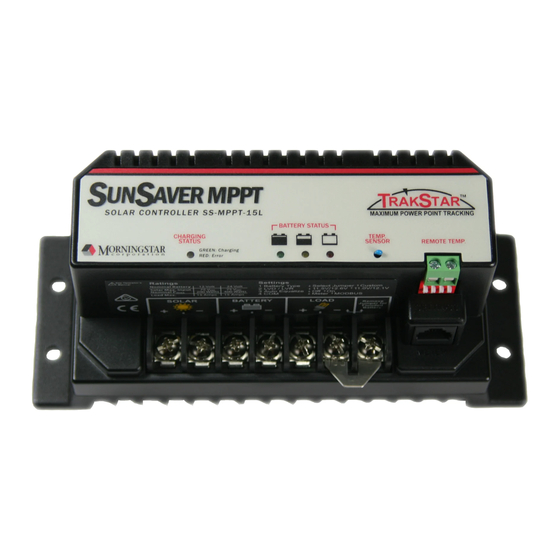
2.2 Features The features of the SunSaver MPPT are shown in Figure 1 below. An explanation of each feature is provided. Figure 1. SunSaver MPPT features. 1 - Status LED An LED indicator that shows charging status and also indicates when a solar input fault condition exists. 2 - Power Terminal Block Power terminations for system Solar, Battery, and Load connections. - Page 11 4 - Meter Connection A communication port for the Morningstar Remote Meter or Personal Computer (PC) connection. A MSC adapter is required, available separately. 5 - Settings Switches Adjustment switches that define the operating parameters of the SunSaver MPPT. 6 - Remote Temperature Sensor (RTS) Terminals Connection point for a Morningstar RTS (optional) to remotely monitor battery temperature.
-
Page 12: Optional Accessories
2.3 Optional Accessories The following accessories are available for purchase separately from your authorized Morningstar dealer. Remote Temperature Sensor (Model: RTS) The RTS measures battery temperature for accurate temperature compensation and is recommended when the ambient battery temperature differs from the ambient controller temperature by +/- 5 degrees C or more. -
Page 13: Regulatory Information
FCC requirements: This device complies with Part 15 of the FCC rules. Operation is subject to the following two conditions: (1) This device may not cause harmful interference, and (2) MORNINGSTAR CORPORATION... - Page 14 Changes or modifications not expressly approved by Morningstar for compliance could void the user’s authority to operate the equipment. Note: This equipment has been tested and found to comply with the limits for a Class B digital device, pursuant to Part 15 of the FCC rules.
-
Page 15: Installation Instructions
The fol- lowing instructions refer to a singular battery, but it is implied that the battery connection can be made to either one battery or a group of batteries in a bat- tery bank. MORNINGSTAR CORPORATION... -
Page 16: Configuration
3.2 Configuration The four (4) Settings Switches and the Battery Select Jumper adjust the SS-MPPT battery type, load control, equalization, and communication settings. This section details the configuration for each setting. Select a Battery Type The SS-MPPT provides four (4) different battery types as shown in table 1 below. - Page 17 (flooded battery type only) every 28 days or if the battery discharges too low the previous night. There is no equalization charge for the gel or sealed battery type. SWITCH 3 OFF (↓): AUTO-EQUALIZE OFF SWITCH 3 ON (↑): AUTO-EQUALIZE ON (agm, flooded battery type only) MORNINGSTAR CORPORATION...
- Page 18 MORNINGSTAR REMOTE METER SWITCH 4 ON (↑): MODBUS® PROTOCOL FOR MSVIEW, 3RD PARTY DEVICES (2) Morningstar PC Meterbus Adapter (Model: MSC) required. Not included. See Morningstar’s website for more information. www.morningstarcorp.com. MODBUS® is a registered trademark of Modbus-IDA (www.modbus-ida.org) 3.0 INSTALLATION INSTRUCTIONS...
-
Page 19: Mounting
Step 2: Check for Clearance Place the SunSaver-MPPT in the location where it will be mounted. Verify that there is sufficient room to run wires and that there is ample room above and below the controller for air flow. MORNINGSTAR CORPORATION... - Page 20 AT LEAST WARM AIR 6” (150 mm) AT LEAST COOL AIR 6” (150 mm) Figure 3. Mounting and cooling Step 3: Mark Holes Use a pencil or pen to mark the four (4) mounting hole locations on the mounting surface. Step 4: Drill Holes Remove the controller and drill 3/32”...
-
Page 21: Wiring
EXPLOSION HAZARD - DO NOT DISCONNECT WHILE CIRCUIT IS LIVE UNLESS AREA IS KNOWN TO BE NON-HAZARDOUS. AVERTISSEMENT: RISQUE D’EXPLOSION. NE PAS DEBRANCHER TANT QUE LE CIRCUIT EST SOUS TENSION, A MOINS QU’lL NE S’AGISSE D’UN EMPLACEMENT NON DANGEREUX. MORNINGSTAR CORPORATION... - Page 22 Step 1: Load Wiring The SS-MPPT load output connection will provide battery voltage to system loads such as lights, pumps, motors, and electronic devices. See Section 4.4 Load Control Information for more details about load control. LOAD 25 AMP POSITIVE (+) FUSE LOAD NEGATIVE (-)
- Page 23 It must be over 7 volts to power the controller. For 24 volt systems, the battery voltage must be greater than 15.5 volts to properly detect a 24V battery. The 12/24 volt battery detection is automatic and the check is only performed at start-up. MORNINGSTAR CORPORATION...
- Page 24 Connect the battery to the SS-MPPT. Refer to the wire gauge chart on page 41 of this manual for correct wire size. If required, the negative battery connection may be earth grounded. Use appropriate gauge wire and proper grounding methods for the installation site. Wire an in-line fuse holder no more than 6 inches (150 mm) from the battery positive terminal.
- Page 25 SS-MPPT 75 Volt maximum solar input rating. The solar module(s) nominal voltage must be equal to or greater than the nominal battery voltage. For 24 V systems, a 24 V or 36 V nominal solar array must be used. MORNINGSTAR CORPORATION...
- Page 26 36 V NOMINAL MAX. 12 Volt 12 Volt 12 Volt MODULE MODULE MODULE SOLAR SOLAR POSITIVE (+) NEGATIVE (-) EARTH GROUND Figure 6. Solar input wiring. Connect the solar module(s) to the SS-MPPT. Refer to the wire gauge chart on page 41 of this manual for correct wire size.
- Page 27 The SS-MPPT should begin the power-up LED sequence when battery power is applied. Observe that the Battery Status LEDs blink in sequence one time. If the SS- MPPT does not power up or a flashing LED error sequence exists, refer to Section 6.0 Troubleshooting. MORNINGSTAR CORPORATION...
-
Page 28: Operation
4.0 Operation 4.1 LED Indications STATUS LED The Status LED indicates charging status and any existing solar input error conditions. The Status LED is on when charging during the day and off at night. The Status LED will flash red whenever an error condition(s) exists. Table 2 lists the Status LED indications. - Page 29 (1 Flash / sec) (Load On) On solid Battery Empty (Load Off) Table 3. Battery SOC LED definitions NOTE: An error condition exists if multiple Battery SOC LEDs are flashing. See Section 5.1 Error Indications for more information. MORNINGSTAR CORPORATION...
-
Page 30: Trakstar Tm Mppt Technology
4.2 TrakStar MPPT Technology The SS-MPPT utilizes Morningstar’s TrakStar Maximum Power Point Tracking technology to extract maximum power from the solar module(s). The tracking algorithm is fully automatic and does not require user adjustment. Trakstar technology will track the array maximum power point voltage... - Page 31 17 V. Figure 8 shows a typical current vs. voltage output curve for a nominal 12V off-grid module. MAXIMUM POWER POINT BATTERY VOLTAGE RANGE VOLTAGE 10 V 15 V ~17 V Figure 8. Nominal 12 V Solar Module I-V curve MORNINGSTAR CORPORATION...
- Page 32 The array V is the voltage where the product of current and voltage (Amps x Volts) is greatest, which falls on the “knee” of the solar module I-V curve as shown in Figure 8. Because Traditional controllers do no operate at the V of the solar array, energy is wasted that could otherwise be used to charge the battery and power system loads.
-
Page 33: Battery Charging Information
Float After the battery is fully charged the SS-MPPT reduces the battery voltage to a float charge which is sometimes called a trickle charge. Depending on battery history, the battery remains in the MORNINGSTAR CORPORATION... - Page 34 absorption stage for 3 or 4 hours before transitioning to the float stage. Equalize (flooded battery type only) If the auto-equalize feature is enabled, the SS-MPPT will equalize a flooded battery for three (3) hours every 28 days. Equalize charging raises the battery voltage above the standard absorption voltage so that the electrolyte gasses.
-
Page 35: Load Control Information
LVD without the current compensation feature. LVD and LVR setpoints are adjusted lower per the following table. System Voltage Current Compensation 12 Volt -15 mV per amp of load 24 Volt -30 mV per amp of load Table 4. Current compensation values. MORNINGSTAR CORPORATION... - Page 36 LVD Warning As the battery discharges the Battery Status LEDs will transition from green to yellow and then from yellow to flashing red. The flashing red indication is a warning that a low voltage disconnect event will occur soon. The amount of time between a green SOC indication and load disconnect will depend on many factors including: •...
-
Page 37: Protections
Load Short Circuit (Battery Status LEDs: R/Y-G sequencing) Fully protected against load wiring short-circuits. After two (2) automatic load reconnect attempts (10 seconds between each attempt), the fault must be cleared by removing and reapplying power. MORNINGSTAR CORPORATION... - Page 38 (Charging Status LED: R on solid) The local ambient temperature sensor is short-circuited or damaged. Charging stops to avoid over- or under-charging. This is a critical error. Contact your authorized Morningstar dealer for service. Damaged Internal Temperature Sensor (Charging Status LED: R on solid) The internal heatsink temperature sensor is damaged.
-
Page 39: Inspection And Maintenance
• If applicable, check enclosure ventilation and air flow holes for obstructions. • Verify LED indication is consistent with the present system conditions. • Verify that the Remote Temperature Sensor (if used) is securely attached to the RTS terminals. MORNINGSTAR CORPORATION... -
Page 40: Programming Custom Setpoints
Custom charging and load set-points can be programmed into SS- MPPT non-volatile memory using a PC with Morningstar MSView software installed and a Meterbus to Serial Adapter (model: MSC). Refer to the MSView help files for detailed instructions. MSView PC software is available for free on our website at: http://www.morningstarcorp.com/... -
Page 41: Troubleshooting
5.0 Troubleshooting 5.1 Error Indications NOTE: If an optional Morningstar Remote Meter is attached to the SunSaver MPPT , use the self-diagnostic feature to determine the cause of the error indication. Refer to the Remote Meter Operator’s Manual for more information. -
Page 42: Common Problems
5.2 Common Problems Problem: No LED indications Solution: With a multi-meter, check the voltage at the battery terminals on the SS-MPPT. Battery voltage must be at least 7V to power the SS-MPPT. Problem: The SS-MPPT is not charging the battery. Solution: If the Status LED is solid or flashing red, see Section 5.1 Error Indications. -
Page 43: Warranty
The SunSaver MPPT charge controller is warranted to be free from defects in material and workmanship for a period of FIVE (5) years from the date of shipment to the original end user. Morningstar will, at its option, repair or replace any such defective products. -
Page 44: Technical Specifications
7.0 Technical Specifications Electrical Nominal system voltage 12 or 24 Vdc Max. battery current 15 A Battery voltage range 7 V – 36 V Max. solar input voltage 75 V Nominal Maximum Input Power* 12 Volt 200 Watts 24 Volt 400 Watts Self-consumption 35 mA... - Page 45 A 15 V (30 V @ 24 V nominal) maximum battery voltage limit prevents damage to sensitive DC loads. Environmental Ambient Temperature Range -40°C to +60°C Storage temperature -55°C to +100°C Humidity 100% N.C. Enclosure IP10 (indoor) MORNINGSTAR CORPORATION...
- Page 46 Mechanical Power terminals wire size (max.) Solid #6 AWG / 16 mm2 Multistrand #6 AWG / 16 mm2 Fine strand #8 AWG / 10 mm2 Terminal Diameter 0.210 in / 5.4 mm Power terminals torque (max.) 35 in-lb / 4 Nm RTS terminals wire size (max.) Wire gauge (min) #22 AWG / 0.3 mm2...
- Page 47 Figure 11. SS-MPPT 24 Volt Efficiency Curves Figure 12. Output Current vs. Heatsink Temperature MORNINGSTAR CORPORATION...
- Page 48 • Immunity: EN61000-6-2:1999 • Emissions: EN55022:1994 with A1 and A3 Class B1 • Safety: EN60335-1 and EN60335-2-29 (battery chargers) Specifications subject to change without notice. Designed in the U.S.A. Assembled in Taiwan © 2013 Morningstar Corporation MS-ZMAN-SSPPT-C 7.0 TECHNICAL SPECIFICATIONS...
-
Page 49: Appendix A - Wire Chart
3% Voltage drop, Annealed copper wire at 20 36 Volt Nominal Wire Chart One-way Wire Distance (feet) One-way Wire Distance (meters) Wire Gauge (AWG) Wire Gauge (mm amps 13.0 1368 ° 3% Voltage drop, Annealed copper wire at 20 MORNINGSTAR CORPORATION...
Need help?
Do you have a question about the SUNSAVER MPPT Series and is the answer not in the manual?
Questions and answers