Table of Contents
Advertisement
Quick Links
Advertisement
Table of Contents

Related Manuals for Rockwell Automation Allen-Bradley Guardmaster CIP


Summary of Contents for Rockwell Automation Allen-Bradley Guardmaster CIP
- Page 1 User Manual Original Instructions CIP Safety Encoder Bulletin Number 843ES...
- Page 2 If this equipment is used in a manner not specified by the manufacturer, the protection provided by the equipment may be impaired. In no event will Rockwell Automation, Inc. be responsible or liable for indirect or consequential damages resulting from the use or application of this equipment.
-
Page 3: Table Of Contents
Protected Operations......... . 28 Rockwell Automation Publication 843ES-UM001A-EN-P - February 2020... - Page 4 Electronic Keying ..........51 Add the Device to the Controller Organizer ..... 52 Rockwell Automation Publication 843ES-UM001A-EN-P - February 2020...
- Page 5 ............93 Index Rockwell Automation Publication 843ES-UM001A-EN-P - February 2020...
- Page 6 Table of Contents Notes: Rockwell Automation Publication 843ES-UM001A-EN-P - February 2020...
-
Page 7: Preface
• When the phrase Logix 5000 controller is used in this publication, it refers to any of the following controller families: – ControlLogix® 5580 or GuardLogix 5580 – CompactLogix™ 5380 or Compact GuardLogix 5380 Rockwell Automation Publication 843ES-UM001A-EN-P - February 2020... -
Page 8: Terminology
Safety network number, which uniquely identifies a network across all networks in the safety system. Safety Network Number You are responsible for assigning a unique number for each safety network or safety subnet within a system. Rockwell Automation Publication 843ES-UM001A-EN-P - February 2020... -
Page 9: Additional Resources
AG-7.1 A glossary of industrial automation terms and abbreviations. Industrial Automation Wiring and Grounding Guidelines, publication 1770-4.1 Provides general guidelines for installing a Rockwell Automation industrial system. Product Certifications website: rok.auto/certifications Provides declarations of conformity, certificates, and other certification details. - Page 10 Preface Notes: Rockwell Automation Publication 843ES-UM001A-EN-P - February 2020...
-
Page 11: Product Overview
Multi-turn units assign a unique digital output for each shaft position across multiple shaft rotations and have high-resolution capability. Applications include steel mills, overhead cranes, punch presses, transfer lines, oil rigs, wind mills, machine tools, and packaging. Rockwell Automation Publication 843ES-UM001A-EN-P - February 2020... -
Page 12: Single-Turn Vs. Multi-Turn Encoders
The steps per revolution can be scaled in integers from 1…262,144 for the standard connection, and 1…32,768 for the safety connection. The total resolution of the 843ES CIP Safety multi-turn encoder must be 2n times the steps per revolution. Rockwell Automation Publication 843ES-UM001A-EN-P - February 2020... -
Page 13: Product Label
KCC marking Date of manufacture TÜV marking ODVA conformance and EtherNet I/P marking Operating temperature, supply voltage, current consumption, and washdown rating CIP serial number MAC ID UL marking RCM marking WEEE marking Rockwell Automation Publication 843ES-UM001A-EN-P - February 2020... -
Page 14: Product Selection
Male 1 Brown 1 Brown 4 Black 4 Black 2 White 2 White 5 NA 5 Gray 3 Blue 3 Blue 1 Brown 4 Black 2 White — 5 Drain wire 3 Blue Rockwell Automation Publication 843ES-UM001A-EN-P - February 2020... - Page 15 Transmit Data - 3 White/Green Receive Data + 1 White-Orange 3 Orange 4 NA — 2 White-Green 4 Green 5 NA — 6 Green Receive Data - 7 NA — 8 NA — Rockwell Automation Publication 843ES-UM001A-EN-P - February 2020...
- Page 16 (1) The 2 at the end of the cat. no. is for 2 m (6.6 ft) cable length. Replace the 2 with 1 (1 m [3.3 ft]), 5 (5 m [16.4 ft]) or 10 (10 m [32.8 ft]) for standard cable lengths. Rockwell Automation Publication 843ES-UM001A-EN-P - February 2020...
-
Page 17: Safety Concept
IMPORTANT Requirements are based on the standards current at the time of certification. The encoder must be installed in accordance with the applicable regulation and standards. For product certifications currently available from Rockwell Automation, see the Product Certifications website link in Additional Resources on page... -
Page 18: Determine Conformity
Correct use includes compliance with the relevant requirements for installation and operation, in particular: • ISO 13849-1, Safety of machinery. Safety-related parts of control systems. General principles for design Rockwell Automation Publication 843ES-UM001A-EN-P - February 2020... - Page 19 ISO 13849-1. You can use 843ES CIP Safety encoders in such an application to achieve SIL 3 and PLe, Cat. 3. For more information on the suitability level of Logix 5000™ safety controllers, see publication 1756-RM012. Rockwell Automation Publication 843ES-UM001A-EN-P - February 2020...
-
Page 20: Average Frequency Of A Dangerous Failure
IMPORTANT Verify that the firmware revision of the device is correct before commissioning the system. Firmware information for safety I/O devices is available with the safety certificates at rok.auto/certifications. Rockwell Automation Publication 843ES-UM001A-EN-P - February 2020... -
Page 21: Safety Function During Firmware Update
Only download firmware and access product release notes from the Product Compatibility and Download Center (rok.auto/pcdc). IMPORTANT Do not download firmware from non-Rockwell Automation sites. Safety Function During Firmware Update The 843ES CIP Safety encoders are not safety capable when a firmware update is in process. -
Page 22: Install And Replace Encoders
The safety controller creates the safety signatures. The safety signature consists of an identification number, date, and time that uniquely identifies the safety portion of a project. This includes all safety logic, data, and safety I/O configuration. Rockwell Automation Publication 843ES-UM001A-EN-P - February 2020... -
Page 23: Controller-Based Safety Functions
All safety-related components of the control system must be included in both a risk assessment and the determination of the achieved levels. See ISO 13849-1, IEC 61508, and IEC 62061 standards for complete information on requirements for PL and SIL determination. Rockwell Automation Publication 843ES-UM001A-EN-P - February 2020... -
Page 24: Compatible Safety Controllers
EtherNet/IP network. Feedback from the encoder is supported in both the safety task and non-safety task. See publication 1756-RM095, for more information on safe motion-monitoring instructions. Rockwell Automation Publication 843ES-UM001A-EN-P - February 2020... -
Page 25: Configuration Signature And Ownership
Each safety device has a unique configuration signature that defines the module configuration. The configuration signature includes the following: • ID number • Date • Time The configuration signature is used to verify the configuration of a module. Rockwell Automation Publication 843ES-UM001A-EN-P - February 2020... -
Page 26: Reset An 843Es Cip Safety Encoder To Out-Of-Box State
• There are pending edits to the module properties. • When a safety signature exists in the controller project. You use the Studio 5000 Logix Designer application to configure the encoder. Rockwell Automation Publication 843ES-UM001A-EN-P - February 2020... -
Page 27: Safety Connection
Safety Output Assembly Tag Name Type/ Description [bit] (Output to Safety Controller) module:SO.Encoder.SetZeroPosition BOOL 0 = OK, 1 = Reset the encoder Position value, by applying the value in Preset of the configuration assembly Rockwell Automation Publication 843ES-UM001A-EN-P - February 2020... -
Page 28: Protected Operations
- Change the project while it is online and click Apply or OK in the Module Properties dialog box. In this case, before the change is made, a dialog box alerts you of the ramifications before the change is made. Rockwell Automation Publication 843ES-UM001A-EN-P - February 2020... -
Page 29: Mechanical
The values that are specified for the radial and axial offset are maximum values, which must not occur simultaneously. If shaft displacements nevertheless occur simultaneously, their share in the sum must not exceed 100% of the specified maximum values. Rockwell Automation Publication 843ES-UM001A-EN-P - February 2020... -
Page 30: Before You Begin
Consider the following when you procure or install couplings: • Counter-torque of the encoder • Maximum permissible shocks and vibrations • Maximum permissible acceleration • Permissible geometrical deviations in the ideal orientation of the shafts • Permissible temperature and humidity ranges Rockwell Automation Publication 843ES-UM001A-EN-P - February 2020... -
Page 31: Screws And Screwed Connections
IMPORTANT For assembly, use only checked and calibrated tools. Shaft Rotation Direction When you view the encoder from the shaft side, the shaft rotation is clockwise (CW) or counterclockwise (CCW), as shown in Figure Figure 3 - Shaft Rotation Rockwell Automation Publication 843ES-UM001A-EN-P - February 2020... -
Page 32: Mount With A Solid Shaft
65.5 (2.5 ) 17° 35° 55 (2.17) ØD f7 Ø59 Ø5 (2.32) (2.2 ) 10 (0.39) 3 (0.12) 3 (0.12) Ø36 (1.42) (0.12 ) 20 (0.79) 22.225 (0. 75) - 3/ in. shaft Rockwell Automation Publication 843ES-UM001A-EN-P - February 2020... - Page 33 75.5 (2.97) 6 (2.6 ) 57.5 (2.26) ØD f7 52.4 Ø59 (2.06) (2.32) 63.5 (2.5) 7.5 (0.3) 7.1 (0.2 ) Ø36 (1.42) (0.12 ) 20 (0.79) 22.225 (0. 75) - 3/ in. shaft Rockwell Automation Publication 843ES-UM001A-EN-P - February 2020...
-
Page 34: Mount With A Hollow Shaft
Tighten the screws to 1 N•m [8.9 lb•in]. 7. Tighten the clamping ring screw to 2.5 N•m (22.1 lb•in). 8. Align machine to its mechanical zero or home position. Rockwell Automation Publication 843ES-UM001A-EN-P - February 2020... -
Page 35: Mechanical Specifications
Ø3.2 (0.13) 75.5 (2.97) Insertion 25.5 (1) max 30 (1.1 ) max Figure 8 - Application Side Requirements for Hollow Shaft Encoders Ra 1.6 Material: Stainless steel Mechanical Specifications Appendix A on page Rockwell Automation Publication 843ES-UM001A-EN-P - February 2020... -
Page 36: Temperature Measurement
Depending on the temperature at the flange, the rotational speed may change. Figure 9 - Derated Rotational Speed 7000 7000 6000 6000 5000 5000 4000 4000 3000 3000 2000 2000 1000 1000 Ambient Temperature [°C] Ambient Temperature [°F] Rockwell Automation Publication 843ES-UM001A-EN-P - February 2020... -
Page 37: Disassembly
• The screws can be newly secured against loosening. • All safety instructions have been complied with. • All the steps that are described in Mechanical on page 29 have been conducted and complied with. Rockwell Automation Publication 843ES-UM001A-EN-P - February 2020... -
Page 38: Electrical
• Comply with the proper operating voltage and the maximum admissible output current. • Use a PELV supply voltage source according to IEC 60204-1. To meet UL requirement, a Class 2 power supply is required for North America. Rockwell Automation Publication 843ES-UM001A-EN-P - February 2020... -
Page 39: Cabling
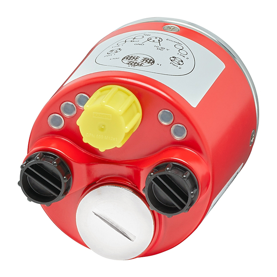
A 4-pin M12 connector is used for the power supply connection. Two 4-pin M12 connectors are used for the Ethernet connection. Figure 10 - Connectors Encoder (not used) Link 2 Link 1 GND 10…30V DC Port 1 Port 2 Network Address Switches Rockwell Automation Publication 843ES-UM001A-EN-P - February 2020... -
Page 40: Pin Assignments
Receive Data + White green Transmit Data - Orange Pair 2 Receive Data - Green Recommended Patchcords and Cordsets on page 14 for recommended power and Ethernet cordsets. Electrical Specifications Appendix A on page Rockwell Automation Publication 843ES-UM001A-EN-P - February 2020... -
Page 41: Set The Ip Address
4. Cycle power to the encoder. 5. The encoder powers up with the IP address set to 192.168.1.xxx, where xxx is the position of the three network address switches. Figure 11 - Network Address Switches Set to 123 Rockwell Automation Publication 843ES-UM001A-EN-P - February 2020... -
Page 42: Duplicate Ip Address Detection
You can reset the IP address of the device to its factory default value by following Reset the IP Address to these steps: Factory Default 1. Set the switches to 888. 2. Cycle the power. Rockwell Automation Publication 843ES-UM001A-EN-P - February 2020... -
Page 43: Network Topologies
Implicit Protected mode is enabled on the device as soon as I/O connections are established through the device. Implicit Protected mode is enabled on the device as soon as all I/O connections through the device are stopped. Rockwell Automation Publication 843ES-UM001A-EN-P - February 2020... - Page 44 Implicit Protected mode. The following are example alerts that result from an attempt to set IP values on a device when the device is in Implicit Protected mode: • Studio 5000 Logix Designer® application Rockwell Automation Publication 843ES-UM001A-EN-P - February 2020...
-
Page 45: Explicit Protected Mode
While working in protected mode, the device rejects any CIP explicit messages that would change the configuration of the device. For example, you cannot change the IP address, speed, or duplex settings when the device had Explicit Protected mode enabled. Rockwell Automation Publication 843ES-UM001A-EN-P - February 2020... - Page 46 Network Status indicator to turn off, and the Link Status indicator to turn off. 3. Power down the device. 4. Set the switches for normal operation. 5. Power up the device. 6. The device is now in Explicit Protected mode. Rockwell Automation Publication 843ES-UM001A-EN-P - February 2020...
-
Page 47: Chapter 5 Before You Begin
• Be sure that you configured your communication driver (for example, AB_ETH-1 or AB-ETHIP-1) in the RSLinx® Classic software. • Create a Logix Designer application project. The encoder does not work until it has been configured with at least the default configuration. Rockwell Automation Publication 843ES-UM001A-EN-P - February 2020... -
Page 48: Studio 5000 Configuration Software
Ethernet network that the configuration references. When you download module configuration to a controller, the controller attempts to establish a connection to each module in the configuration. Rockwell Automation Publication 843ES-UM001A-EN-P - February 2020... -
Page 49: Requested Packet Interval
You cannot change the status of the tags. Keep in mind that in some system configurations, the tag is not reset immediately after the condition is removed. The tag typically resets after a small delay. Rockwell Automation Publication 843ES-UM001A-EN-P - February 2020... -
Page 50: Inhibit A Module
Program mode, and all outputs change to the state configured for Program mode. For example, if an output module is configured so that the state of the outputs transition to zero during Program mode, whenever that module is inhibited, outputs transition to zero. Rockwell Automation Publication 843ES-UM001A-EN-P - February 2020... -
Page 51: Electronic Keying
Indicates that all keying attributes do not need to match to the established communication. (1) Only available if connection is set for Standard Only. Carefully consider the implications of each keying option when selecting one. Rockwell Automation Publication 843ES-UM001A-EN-P - February 2020... -
Page 52: Add The Device To The Controller Organizer
1. Right-click the Ethernet adapter and choose New Module. This example uses a 1756-L84ES and 1756-L8P, and the encoder is on the network that is connected to the 1 GB Ethernet Port on the 1756-L84ES. Rockwell Automation Publication 843ES-UM001A-EN-P - February 2020... - Page 53 The number and type of categories varies by module type. 3. Click OK to use the default configuration as shown or edit the module configuration. The rest of this chapter describes how to edit module configuration categories. Rockwell Automation Publication 843ES-UM001A-EN-P - February 2020...
-
Page 54: Edit The Module Configuration Common Categories
During configuration, the Logix Designer application defaults an SNN of a safety device to match the SNN of the first safety node on each network. In most cases, you can use the default SNN. Rockwell Automation Publication 843ES-UM001A-EN-P - February 2020... - Page 55 (3) If Standard Only or Safety and Standard connection is set, then Standard Data parameter is set to Data. If Safety Only connection is made, then the Standard Data parameter is set to None. Rockwell Automation Publication 843ES-UM001A-EN-P - February 2020...
-
Page 56: Connection
• Configure whether a connection failure while the controller is in Run module causes a major or minor fault. TIP The Module Fault area of the Connection category is useful during module troubleshooting. Rockwell Automation Publication 843ES-UM001A-EN-P - February 2020... -
Page 57: Safety
IMPORTANT Both standard and safety rated signals are included in the CIP Safety connection. Safety rated signals can be used in safety functions. Standard rated signals can be used in the safety task, but must not be relied on for safety functions. Rockwell Automation Publication 843ES-UM001A-EN-P - February 2020... - Page 58 Figure 12 - Configuration Ownership A communication error is displayed if the module read fails. See Replace an 843ES CIP Safety Encoder in a GuardLogix System on page 61 for integrated safety encoder replacement information. Rockwell Automation Publication 843ES-UM001A-EN-P - February 2020...
- Page 59 (as shown on the safety tab in the Studio 5000 environment), the device must first be reset to out-of-box condition (see Reset to Out-of-Box Configuration on page 58). Rockwell Automation Publication 843ES-UM001A-EN-P - February 2020...
- Page 60 5. From the General tab, click Safety Network Number. The SNN dialog box appears. Enter the Number, Click Set, then click OK. 6. Select Yes to continue. 7. The module status changes from Faulted to Running, in the lower left corner of the General tab. Rockwell Automation Publication 843ES-UM001A-EN-P - February 2020...
- Page 61 Rockwell Automation Publication 843ES-UM001A-EN-P - February 2020...
- Page 62 Configure Always feature is enabled. For the device replacement procedure, see Additional Resources on page 9 for the appropriate user manual for your GuardLogix or Compact GuardLogix controller. Rockwell Automation Publication 843ES-UM001A-EN-P - February 2020...
-
Page 63: Module Info
For more information on setting IP address, see Chapter 4 on page You can use this page to complete the following: • Set IP configuration settings • Manually configure the IP settings • Refresh the communication Rockwell Automation Publication 843ES-UM001A-EN-P - February 2020... -
Page 64: Port Configuration
• Network Status: Displays the current network status as normal, ring fault, or unexpected loop detected. • The Refresh Communication link appears when communication with the encoder has failed. Click Refresh Communication to attempt to restart communication with the encoder. Rockwell Automation Publication 843ES-UM001A-EN-P - February 2020... -
Page 65: Edit 843Es Cip Safety Encoder Configuration Categories
Use this parameter to define the units in which the velocity and acceleration is transmitted. The options are the following: Velocity Unit Selected Acceleration Unit Used Counts/second Counts/second2 Counts/milliseconds Counts/milliseconds2 Revolutions/second Revolutions/minute Revolutions/second2 Revolutions/hour Rockwell Automation Publication 843ES-UM001A-EN-P - February 2020... - Page 66 Range is the total resolution of the encoder in counts. Range is resolution multiplied by the number of revolutions. If you change resolution or revolutions, the range changes automatically. Range must be a value between 4…134,217,728. Rockwell Automation Publication 843ES-UM001A-EN-P - February 2020...
-
Page 67: Encoder Standard Configuration
Enter the position offset value in counts. The Preset is applied to position value when SetZeroPosition is true. The maximum value is 1 less than the total measuring range of the encoder as configured by the position scaling. Rockwell Automation Publication 843ES-UM001A-EN-P - February 2020... - Page 68 Range is the total resolution of the encoder in counts. Range is resolution multiplied by the number of revolutions. If you change resolution or revolutions, the range changes automatically. Range must be a value between 4…1,073,741,824. Rockwell Automation Publication 843ES-UM001A-EN-P - February 2020...
-
Page 69: Alarms
The Alarms tab is also where the units for temperature are set. If any units are changed, the parameters on the Alarms tabs are reset to their defaults. The defaults are converted correspondingly and overwrite the current setpoint value of the affected attributes. Rockwell Automation Publication 843ES-UM001A-EN-P - February 2020... -
Page 70: Controller Tags
The value is always the opposite of Internal Fault. Position DINT Position in number of counts Velocity REAL Current velocity. The velocity units define the format. Acceleration REAL Current acceleration. The acceleration units define the format. Rockwell Automation Publication 843ES-UM001A-EN-P - February 2020... - Page 71 Accel DINT Current acceleration. The acceleration units define the format (1) Alarm setpoint limits are defined in the Logix Designer encoder module properties Alarms page, see Alarms on page 69 for more detail. Rockwell Automation Publication 843ES-UM001A-EN-P - February 2020...
- Page 72 Table 22 - Encoder Channel Output Data Type (CHANNEL_ENC:O:0) Member Name Data Type Description SetZeroPositon BOOL 0 = OK, 1 = Reset the encoder Position value, by applying the value in Preset of the configuration assembly Rockwell Automation Publication 843ES-UM001A-EN-P - February 2020...
-
Page 73: Chapter 6 Status Indicators
Figure 14 - Status Indicator Location Encoder (not used) Link 2 Link 1 GND 10…30V DC Port 1 Port 2 Read the status indicators according to Table 23 on page Rockwell Automation Publication 843ES-UM001A-EN-P - February 2020... -
Page 74: Warnings, Alarms, And Errors Via Ethernet/Ip
For errors, alarms, and warning the following applies: • Bit status = 0: no error, alarm, or warning • Bit status =1: error, alarm, or warning present • In addition, the Net status indicator illuminates red continuously. Rockwell Automation Publication 843ES-UM001A-EN-P - February 2020... -
Page 75: Warnings
Reserved by CIP — Always 0 — Vendor: Out of Temperature setpoints reached Temperature out of range range Vendor: over/under voltage Out of Supply voltage outside permissible range (9.700…30.300mV) range Not supported — Always — Rockwell Automation Publication 843ES-UM001A-EN-P - February 2020... -
Page 76: Alarms
Alarm has been dropped below. The upper limit for the temperature that is configured with High Limit ERROR Temperature Alarm has been exceeded. (1) Alarms are not available in the Safety Position Sensor Object. Rockwell Automation Publication 843ES-UM001A-EN-P - February 2020... -
Page 77: Errors
Bad Safety Protocol Format An error occurred while trying to add the Safety Network Segment to a route in Logix. Check Safety Network Number on Safety Page, refresh Safety Network Number if needed. Rockwell Automation Publication 843ES-UM001A-EN-P - February 2020... - Page 78 Chapter 6 Diagnostics and Troubleshooting Notes: Rockwell Automation Publication 843ES-UM001A-EN-P - February 2020...
-
Page 79: General
= 8.03E-9 (average frequency of a dangerous failure per hour) Certifications CE Marked for all applicable directives, c-UL-us (UL 61010), and TÜV, see rok.auto/certifications Mission time 20 years Diagnostic coverage (DC) ≥99% Error presumptions IEC 61800-5-2 CIP Safety ODVA CIP Volume 5 Rockwell Automation Publication 843ES-UM001A-EN-P - February 2020... -
Page 80: Electrical
≥25.5 mm (1.0 in.) Flanges [mm (in.)] 58 (2.28) Clamp flange, With stator coupling, 63 (2.48) 58 (2.28) Synchro flange, 63.5 (2.5) Square flange Power connector 4-pin, male, A-coded Weight 0.45 kg (15.87 oz) approximately Rockwell Automation Publication 843ES-UM001A-EN-P - February 2020... -
Page 81: Environmental
4096 turns (12 bit) Safe absolute resolution 32,768 counts per turn (15 bit) 4096 turns (12 bit) Smallest safe measuring step 158.4 arcsec (0.044°) Startup time 10 s Code direction CW or CCW programmable Rockwell Automation Publication 843ES-UM001A-EN-P - February 2020... - Page 82 Appendix A Specifications Notes: Rockwell Automation Publication 843ES-UM001A-EN-P - February 2020...
-
Page 83: Appendix B Introduction
This appendix shows how to install the Add-on Profile (AOP) of the encoder Introduction with the Studio 5000 Logix Designer application. Add-on Profiles are files that users add to their Rockwell Automation library. These files contain the pertinent information for configuring a device that is added to the Rockwell Automation network. - Page 84 IMPORTANT The shown Module Profile revisions may be different than what is shown in the preceding image. 6. To accept the licensing terms, click the radio button, then click Next. 7. Click the Install radio button and then click Next. Rockwell Automation Publication 843ES-UM001A-EN-P - February 2020...
- Page 85 Install an Add-on Profile Appendix B 8. Click Install to begin the installation. 9. Click Next to install the Add-on Profile files. 10. Click Finish to complete the installation. Rockwell Automation Publication 843ES-UM001A-EN-P - February 2020...
- Page 86 Appendix B Install an Add-on Profile Notes: Rockwell Automation Publication 843ES-UM001A-EN-P - February 2020...
-
Page 87: Safety Statements
• If a Type 1 SafetyOpen configures a device, you must verify that all originator-configured safety devices have their ownership assignments as part of the final verification process. • You must visually verify that all configuration data was downloaded correctly. Rockwell Automation Publication 843ES-UM001A-EN-P - February 2020... - Page 88 Appendix C Safety Statements for Use of CIP Safety Devices Notes: Rockwell Automation Publication 843ES-UM001A-EN-P - February 2020...
-
Page 89: Sfx Instruction
SFX instruction must be verified within your application. When possible, use immediate operands for instructions to reduce the possibility of systematic errors in your ladder program. Instruction operands must be verified for your safety ladder program. Rockwell Automation Publication 843ES-UM001A-EN-P - February 2020... -
Page 90: Sfx Instruction Example
Figure 17, the encoder is monitoring for a rotary application where the unwind is set to rollover each motor revolution. Therefore, the unwind of 512 counts/revolution was added in the SFX instruction appropriately. Rockwell Automation Publication 843ES-UM001A-EN-P - February 2020... - Page 91 You can use safety tags as inputs in the standard or motion control, but not as an output. Rockwell Automation Publication 843ES-UM001A-EN-P - February 2020...
- Page 92 The safety controller tags have been created in place of pass through data tags because safe motion monitoring instance tags are not available. Figure 19 - Drive Safety Instruction SFX Control Instruction Safety Controller Tags in Place of Drive Motion Safety Instance Tags Rockwell Automation Publication 843ES-UM001A-EN-P - February 2020...
-
Page 93: Index
(Studio 5000 environment) 47 safety connection 57 mount 20 configure connection reaction time limit overview 11 (CRTL) 58 safety configuration 65 conformity single-turn vs. multi-turn 12 determine 18 standard configuration 67 environmental specifications 81 Rockwell Automation Publication 843ES-UM001A-EN-P - February 2020... - Page 94 12 installation 29 operation electrical 38 protected 28 mechanical 29 out-of-box state 26 instruction output assembly tags 27 wiring 39 overview intended use 12 encoder 11 internet protocol 63 ownership configuration 25 Rockwell Automation Publication 843ES-UM001A-EN-P - February 2020...
- Page 95 81 shaft 31 general 79 rotational speed mechanical 80 resolution/revolution 81 derated 36 safety 79 RPI 49 speed definition 8 standard deviation 80 RSLinx Classic standard check EtherNet/IP integration 48 configuration encoder 67 Rockwell Automation Publication 843ES-UM001A-EN-P - February 2020...
- Page 96 Studio 5000 configuration software 48 Studio 5000 environment configure encoder 47 controller 70 task safety 24 temperature measurement 36 topology network 43 troubleshooting 73 intended 12 warning 75 EtherNet/IP 74 wiring instruction 39 Rockwell Automation Publication 843ES-UM001A-EN-P - February 2020...
- Page 98 Rockwell Automation maintains current product environmental information on its website at http://www.rockwellautomation.com/rockwellautomation/about-us/sustainability-ethics/product-environmental-compliance.page. Allen-Bradley, CompactLogix, ControlFLASH, ControlLogix, GuardLogix, Guardmaster, Kinetix, Logix 5000, Rockwell Automation, Rockwell Software, RSLinx, RSLogix 5000, Safety Automation Builder, Studio 5000, and Studio 5000 Logix Designer are trademarks of Rockwell Automation, Inc.
Need help?
Do you have a question about the Allen-Bradley Guardmaster CIP and is the answer not in the manual?
Questions and answers