Table of Contents
Advertisement
Quick Links
Advertisement
Table of Contents

Subscribe to Our Youtube Channel
Related Manuals for Rockwell Automation Allen-Bradley 842E-CM


Summary of Contents for Rockwell Automation Allen-Bradley 842E-CM
- Page 1 842E-CM Integrated Motion Encoder on EtherNet/IP User Manual...
- Page 2 Identifies information that is critical for successful application and understanding of the product. IMPORTANT Rockwell Automation, Allen-Bradley, CompactLogix, Kinetix, PanelView, POINT I/O, RSLinx, RSLogix, Stratix 5700, and Studio 5000 are trademarks of Rockwell Automation, Inc. Trademarks not belonging to Rockwell Automation are property of their respective companies.
-
Page 3: Table Of Contents
192.168.1.xxx Using the Network Address Switches..26 Assigning the IP Address Using BootP/DHCP:....26 Rockwell Automation Publication 842E-UM002A-EN-P- November 2013... - Page 4 Data Monitor..........62 Rockwell Automation Publication 842E-UM002A-EN-P - November 2013...
-
Page 5: Preface
The following conventions are used throughout this manual: • Bulleted lists such as this one provide information, not procedural This Manual steps. • Numbered lists provide sequential steps or hierarchical information. • Italic type is used for emphasis. Rockwell Automation Publication 842E-UM002A-EN-P - November 2013... -
Page 6: Requirements
Induction motors with open loop volts/hertz speed control are also supported. Cables Motor cables Bulletin 2090 single-cable for motor power, feedback, and 24V DC brake power. Communication Ethernet cables are available in standard lengths. Shielded cable is recommended. Rockwell Automation Publication 842E-UM002A-EN-P - November 2013... -
Page 7: Terminology
It may serve as the source of time, for example, a Master clock, and may synchronize to another clock, thus being a Slave clock Precision Time Protocol A high-precision time synchronization protocol for networked measurement and (PTP) control systems, defined by the IEEE 1588 standard. Rockwell Automation Publication 842E-UM002A-EN-P - November 2013... - Page 8 Frequency drives are, therefore, sometimes referred to as Volts/Hertz drives TIP Not all servo drives support direct frequency control. Rockwell Automation Publication 842E-UM002A-EN-P - November 2013...
-
Page 9: Related Documentation
For best results, grounding the encoder flange is recommended. IMPORTANT Numerous useful publications are available for download at http://www.rockwellautomation.com/literature. To order paper copies of technical documentation, contact your local Allen-Bradley distributor or Rockwell Automation sales representative. Rockwell Automation Publication 842E-UM002A-EN-P - November 2013... - Page 10 Preface Notes: Rockwell Automation Publication 842E-UM002A-EN-P - November 2013...
-
Page 11: Safety Precautions
ATTENTION: The 842E-CM encoder must only be installed, commissioned, and serviced by authorized personnel. ATTENTION: Repairs to the 842E-CM encoder are allowed to be undertaken only by trained and authorized service personnel from Rockwell Automation. The following qualifications are necessary for the various tasks: Activity... -
Page 12: Correct Use
In case of any other usage of, or modifications to the 842E-CM Integrated Motion encoder, e.g., opening the housing during mounting and electrical installation, or in case of modifications to the Rockwell Automation software, any claims against Rockwell Automation under warranty will be rendered void. General Safety Notes and... -
Page 13: Environmental Protection
Please note the following information on disposal. Assembly Material Disposal Packaging Cardboard Waste paper Shaft Stainless steel Scrap metal Flange Aluminum Scrap metal Housing Aluminum Die-cast Scrap metal Electronic assemblies Various Hazardous waste Rockwell Automation Publication 842E-UM002A-EN-P - November 2013... - Page 14 Chapter 1 Safety Precautions Notes: Rockwell Automation Publication 842E-UM002A-EN-P - November 2013...
-
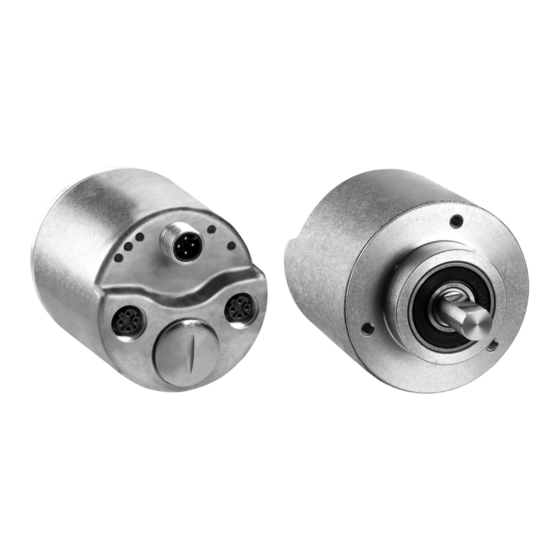
Page 15: About The Encoder
• Ball bearing spacing of 30 mm for longer life • Face mount flange and servo flange/blind hollow shaft and through hollow shaft • 18-bit single turn resolution • 30-bit total resolution multi-turn resolution Rockwell Automation Publication 842E-UM002A-EN-P - November 2013... -
Page 16: Cip Sync Overview
(DLR). Rockwell Automation recommends that you use no more than 50 nodes on a IMPORTANT single DLR or linear network. If your application requires more than 50 nodes, we recommend that you segment the nodes into separate, but linked, DLR or linear networks. -
Page 17: Star Topology
The star structure consists of a number of devices connected to a central switch. When this topology is used, make the Ethernet connection on the 842E-CM IMPORTANT encoder to the Link 1 connection. The Link 2 Ethernet connection must remain unused. Rockwell Automation Publication 842E-UM002A-EN-P - November 2013... -
Page 18: Linear Topology
Kinetix 5500 Se rvo Drive System 1 (Front) 2 (Rear) 1581585J-M8CBJM-OM3 0.3 m (1.0 ft) Ethernet cable 1585J-M8CBJM-x for drive-to-drive connections Ethernet (shi elded) cable 842E-CM encoder 1734-AENTR POINT I/O™ PanelView™ Plus EtherNet/IP Adapter display terminal Rockwell Automation Publication 842E-UM002A-EN-P - November 2013... -
Page 19: Device Level Ring Topology
2 (Rear) 1734-AENTR POINT I/O EtherNet/IP adapter PanelView Plus 1783-ETAP display terminal module Kinetix 5500 servo drive system 1585J-M8CBJM-OM3 0.3 m (1.0 ft) Ethernet cable for drive-to-drive connections. 842E-CM encoder 1585D-M4TBJM-x Ethernet (shielded) cable Rockwell Automation Publication 842E-UM002A-EN-P - November 2013... - Page 20 Chapter 2 About the Encoder Notes: Rockwell Automation Publication 842E-UM002A-EN-P - November 2013...
-
Page 21: Installation
845–FC–*–*. See encoder accessories in the catalog (C116-CA001). ATTENTION: Do not rigidly connect the encoder shaft to the machine; this will cause premature failure of the encoder or machine bearings. Always use a flexible coupling. Rockwell Automation Publication 842E-UM002A-EN-P - November 2013... -
Page 22: Mounting With A Hollow Shaft
6. Attach the encoder with two M4 (or equivalent) screws. IMPORTANT Do not stress the flex mount while tightening the screws. 7. Tighten the clamping ring screw to 1.1 Nm (10 in–lb). Rockwell Automation Publication 842E-UM002A-EN-P - November 2013... -
Page 23: Electrical
Address Switches x100 IMPORTANT For best results, grounding the encoder flange is recommended. Also refer to publication 1770-4.1, Industrial Automation Wiring and Grounding Guidelines, available online at http:// www.rockwellautomation.com/literature/, for additional installation requirements. Rockwell Automation Publication 842E-UM002A-EN-P - November 2013... -
Page 24: Pin Assignments
Code direction CW or CCW programmable Interface EtherNet/IP per IEC 61784-1 IEEE 1588 (IEEE 61588, Precision clock synchronization protocol for networked measurement and control systems) Transmission speed 100 MBits/s Duplex Full or half Rockwell Automation Publication 842E-UM002A-EN-P - November 2013... -
Page 25: Configuring The Encoder
IP address (192.168.1.xxx). 2. Use the network address switches to enable BootP / DHCP and use a BootP utility or DHCP server to assign the IP address of the unit on powerup. Rockwell Automation Publication 842E-UM002A-EN-P - November 2013... -
Page 26: Assigning The Last Octet In An Ip Address Scheme Of
5. The encoder will power up and request an IP address from a BootP/ DHCP server. 6. If the MAC ID of the encoder is in the relationship list, the BootP/ DHCP server will assign the associated IP address to the corresponding MAC ID. Rockwell Automation Publication 842E-UM002A-EN-P - November 2013... - Page 27 842E-CM encoder to retain the IP address at the next power cycle. Wait for the status message to show that the command was successfully sent. If the message does not appear, repeat this step. Rockwell Automation Publication 842E-UM002A-EN-P - November 2013...
- Page 28 Chapter 4 Configuring the Encoder Notes: Rockwell Automation Publication 842E-UM002A-EN-P - November 2013...
-
Page 29: Example: Setting Up The Hardware
To work along with this example, configure the system as shown. • Verify the IP addresses for your programming terminal and 842E- CM encoder. • Verify that you properly connected all wiring and cabling. Rockwell Automation Publication 842E-UM002A-EN-P - November 2013... -
Page 30: Checking The Integration In Ethernet/Ip Via Rslinx Classic
3. Then open the path AB_ETHIP1, Ethernet. The encoder can be seen with its IP address. IMPORTANT Before proceeding, install the add-on profile (see Appendix B). 4. Install the add-on profile according to the instructions in Appendix B. Rockwell Automation Publication 842E-UM002A-EN-P - November 2013... -
Page 31: Adding And Configuring The Add-On Profile In Rslogix 5000
2. From the File menu, choose New. The New Controller dialog opens. 3. Select a controller and name it. 4. Click Next. 5. Select the slot your controller is in and configure it. 6. Click Finish. Rockwell Automation Publication 842E-UM002A-EN-P - November 2013... - Page 32 Ethernet bridge, such as the 1756-EN2T, EN2TR, or EN3TR. 12. Right-click on the Ethernet port or Ethernet module of the controller and select New Module. 13. Select the desired 842E-CM encoder (single turn or multi-turn) and click Create. Rockwell Automation Publication 842E-UM002A-EN-P - November 2013...
-
Page 33: Configuring The Encoder
Click an Ethernet Address option. In this example, the Private Network address is selected. c. Enter the address of the encoder. 2. Click the Associated Axes tab. 3. Click New Axis. The New Tag dialog box opens. Rockwell Automation Publication 842E-UM002A-EN-P - November 2013... - Page 34 4. Name the new tag. 5. The data type will be AXIS_CIP_DRIVE. 6. Click Create. The new axis (Master_Fdbk) appears under Motion Groups>Ungrouped Axes in the Controller Organizer and is assigned as Axis 1. 7. Click Apply. Rockwell Automation Publication 842E-UM002A-EN-P - November 2013...
-
Page 35: Configuring The Motion Group
Groups folder. 4. Right-click the new motion group and choose Properties. The Motion Group Properties dialog box opens. 5. Click the Axis Assignment tab and move your axes (created earlier) from Unassigned to Assigned. Rockwell Automation Publication 842E-UM002A-EN-P - November 2013... -
Page 36: Configuring Axis Properties
1. Right-click the axis in the Controller Organizer and choose Properties. 2. Select the General Category. 3. From the General pull-down menus, change configuration settings as needed for your application. 4. From the Associated Module >Module pull-down menu, choose your encoder. Rockwell Automation Publication 842E-UM002A-EN-P - November 2013... - Page 37 The configuration for multi-turn is shown below. For single turn, Turns should be 1. 9. Click Apply. 10. Select the Scaling category and edit the default values as appropriate to your application. If you make changes, click Apply. Rockwell Automation Publication 842E-UM002A-EN-P - November 2013...
- Page 38 12. Enter the desired value for position. This will be the home position. 13. Select Actions. Here you can select the fault exception behavior for your device and the Soft Travel Limits. Shutdown is currently the only available exception behavior. Rockwell Automation Publication 842E-UM002A-EN-P - November 2013...
- Page 39 Configuring the 842E-CM Encoder Using the Logix Designer Application Chapter 5 14. Select Drive Parameters. Check the boxes for desired real-time data. IMPORTANT Firmware revision 1.002 supports the Velocity and Acceleration parameters. Rockwell Automation Publication 842E-UM002A-EN-P - November 2013...
- Page 40 Velocity Threshold: This parameter defines a minimum absolute velocity. If the magnitude of the velocity feedback signal is less than this value, the Velocity Threshold status bit is set. Rockwell Automation Publication 842E-UM002A-EN-P - November 2013...
- Page 41 NOTE: The Source Element must be a REAL data type, and its default value is 6000 rps. c. Click the Communication tab and browse to the encoder tag; in this case, “encoder” as shown. The same procedure is required for the following parameters. Rockwell Automation Publication 842E-UM002A-EN-P - November 2013...
- Page 42 Bandwidth in Hz) This parameter controls the bandwidth of the low pass filter applied to the raw velocity signal from Feedback. Default value: 100 (recommended bandwidth 1 to 1000Hz), Attribute disabled: 0 The source element must be a REAL data type. Rockwell Automation Publication 842E-UM002A-EN-P - November 2013...
- Page 43 Class, Instance and Attribute data, as well as add a destination element to ensure that the correct value was successfully written into the encoder. Refer to the following example to verify the acceleration low pass filter value. Rockwell Automation Publication 842E-UM002A-EN-P - November 2013...
-
Page 44: Testing The Axis
Chapter 5 Configuring the 842E-CM Encoder Using the Logix Designer Application Sample code is available. Visit the Rockwell Automation Sample Code Library, and search for “CIP motion encoder” or “842E-CM. ” To download the sample code with the above information, select Downloads on the following page: http://www.rockwellautomation.com/rockwellautomation/support/... - Page 45 Configuring the 842E-CM Encoder Using the Logix Designer Application Chapter 5 • If you need to change the polarity, select Axis Properties > Polarity. Click the Inverted radio button. Rockwell Automation Publication 842E-UM002A-EN-P - November 2013...
- Page 46 Chapter 5 Configuring the 842E-CM Encoder Using the Logix Designer Application Notes: Rockwell Automation Publication 842E-UM002A-EN-P - November 2013...
-
Page 47: Interpreting Status Indicators
Five LED indicators provide status information on the back of the encoder. The figure below shows their location; the following tables describe their status. XS (Axis) Link 2 Link 1 Screw cove Read the LEDs according to the following tables. Rockwell Automation Publication 842E-UM002A-EN-P - November 2013... - Page 48 The Ethernet link LEDs, Link 1 and Link 2, display the status of the physical connection on the Ethernet interface. Link 1 and Link 2 LEDs Description No power/IP address Green LINK Green flashing Port activity Amber Port disabled Amber flashing Collision Rockwell Automation Publication 842E-UM002A-EN-P - November 2013...
-
Page 49: Faults And Alarms
Encoder Fault and Alarm Subcodes The following table shows the sensor encoder fault and alarm subcodes communicated through the Cyclic Data Channel of the controller. Subcodes will appear in the Axis Fault Log. Rockwell Automation Publication 842E-UM002A-EN-P - November 2013... - Page 50 Exceptions that prevent normal operation of the encoder, but do not result in any action other than reporting the alarm to the controller. INHIBIT Mxx Exceptions that prevent normal operation and indicate whenever the encoder is active. Rockwell Automation Publication 842E-UM002A-EN-P - November 2013...
- Page 51 • Change network topology so that fewer devices share common paths • Use high performance network equipment • Use shielded cables • Separate signal wiring from power wiring Rockwell Automation Publication 842E-UM002A-EN-P - November 2013...
-
Page 52: Cm Exception Behavior
See the Logix Designer Axis Properties screen, Actions category. Table 6 - Encoder Behavior, FLT Sxx Fault Codes Exception fault Exception text Fault action code Ignore Alarm Minor fault Major fault FLT S47 – FDBK Feedback device DEVICE FAILURE failure Rockwell Automation Publication 842E-UM002A-EN-P - November 2013... -
Page 53: Introduction
If firmware revision 1.002 (or higher) is stated on the encoder label, proceed to update the firmware. 1. First, verify successful RSLinx Classic communications with the 842E-CM encoder via EtherNet/IP using RSWho Ethernet or EtherNet/IP driver. Rockwell Automation Publication 842E-UM002A-EN-P - November 2013... - Page 54 Flash Update the 842E-CM Firmware 2. Start ControlFLASH and select Network or Local network. 3. Click Next. 4. Select the catalog number of the 842E-CM encoder whose firmware you wish to upgrade, then click Next. Rockwell Automation Publication 842E-UM002A-EN-P - November 2013...
- Page 55 Flash Update the 842E-CM Firmware Appendix A 5. Select the controller in the browse window, and click OK. 6. Click Next to continue, and verify the revisions. Click Finish and Yes to initiate the upgrade. Rockwell Automation Publication 842E-UM002A-EN-P - November 2013...
- Page 56 8. If you see an error message instead, click OK to clear the window and power cycle the encoder before trying again. 9. Upon successful completion of the flash update, you see an Update complete status screen. Click OK to complete the update. Upon s Rockwell Automation Publication 842E-UM002A-EN-P - November 2013...
-
Page 57: Introduction
This appendix shows how to install the add-on profile (AOP) of the encoder with the RSLogix 5000 program. Add-on profiles are files that users add to their Rockwell Automation library. These files contain the pertinent information for configuring a device that will be added to the Rockwell Automation network. - Page 58 Appendix B Installing the Add-on Profile 5. At the welcome screen, click on Next. 6. Click the radio button to accept the licensing terms, then click Next. Rockwell Automation Publication 842E-UM002A-EN-P - November 2013...
- Page 59 Installing the Add-on Profile Appendix B 7. Click the Install radio button, then click Next. 8. Click Install to begin the installation. Rockwell Automation Publication 842E-UM002A-EN-P - November 2013...
- Page 60 Appendix B Installing the Add-on Profile 9. Click Next to install the add-on profile files. 10. Click Finish to complete the installation. Rockwell Automation Publication 842E-UM002A-EN-P - November 2013...
-
Page 61: Quick View Pane
The Quick View pane gives you a quick summary of faults and alarms related to the axis you select in the Controller Organizer. The information includes the type of axis, description, axis state, faults and alarms. Rockwell Automation Publication 842E-UM002A-EN-P - November 2013... -
Page 62: Data Monitor
Appendix C Faults and Alarms Dialog Box Data Monitor The Data Monitor is where you can read and write the values assigned to specific tags, both online and offline. Rockwell Automation Publication 842E-UM002A-EN-P - November 2013... - Page 64 Americas: Rockwell Automation, 1201 South Second Street, Milwaukee, WI 53204-2496 USA, Tel: (1) 414.382.2000, Fax: (1) 414.382.4444 Europe/Middle East/Africa: Rockwell Automation NV, Pegasus Park, De Kleetlaan 12a, 1831 Diegem, Belgium, Tel: (32) 2 663 0600, Fax: (32) 2 663 0640 Asia Pacific: Rockwell Automation, Level 14, Core F, Cyberport 3, 100 Cyberport Road, Hong Kong, Tel: (852) 2887 4788, Fax: (852) 2508 1846 Publication 842E-UM002A-EN-P–...
Need help?
Do you have a question about the Allen-Bradley 842E-CM and is the answer not in the manual?
Questions and answers