Advertisement
Available languages
Available languages
Quick Links
IB519126EN
Installation Instructions – VRVT3 LED Vaportight Luminaire Installation
Instructions d'installation – Luminaire DEL étanche à la vapeur VRVT3
Instrucciones de instalación – Instalación de la luminaria VRVT3 LED
Vaportight
Risk of Fire, Electrical Shock, Cuts or other Casualty Hazards- Installation and maintenance of this product
must be performed by a qualified electrician. This product must be installed in accordance with the applicable
installation code by a person familiar with the construction and operation of the product and hazards
involved.
Risk of Fire and Electric Shock- Make certain power is OFF before starting installation or attempting any
maintenance. Disconnect power at fuse or circuit breaker.
Risk of Fire- Minimum 90°C supply conductors.
Risk of Burn- Disconnect power and allow fixture to cool before handling or servicing.
Risk of Personal Injury- Due to sharp edges, handle with care.
Must be very careful if power tools are used to install the fixture. Uncontrolled torque setting may lead to
thread/gasket damage or lens breakage.
Failure to comply with these instructions may result in death, serious bodily injury and property damage.
DISCLAIMER OF LIABILITY: Cooper Lighting Solutions assumes no liability for damages or losses of any kind that may
arise from the improper, careless, or negligent installation, handling or use of this product.
IMPORTANT: Read carefully before installing fixture. Retain for future reference.
NOTICE: These instructions do not claim to cover all details or variations in the equipment, procedure, or process
described, or to provide directions for meeting every possible contingency during installation, operation or maintenance.
When additional information is desired to satisfy a problem not covered sufficiently for user's purpose, please contact your
nearest representative.
NOTICE: Proper grounding is required to insure personal safety.
NOTICE: Fixture may become damaged and/or unstable if not installed properly.
Note: Specifications and dimensions subject to change without notice.
ATTENTION Receiving Department:
Note actual fixture description of any shortage or noticeable damage on delivery receipt. File claim for common carrier
(LTL) directly with carrier. Claims for concealed damage must be filed within 15 days of delivery. All damaged material,
complete with original packing must be retained.
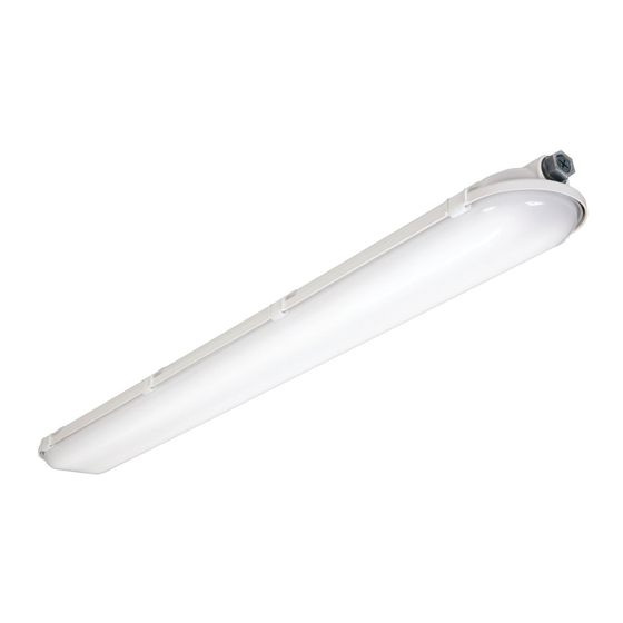
VRVT3 Description
The VRVT3 LED is a Vaportite fixture using a reinforced fiberglass housing with a high impact diffuser. The fixture is
suitable for interior and exterior applications and can be surface or chain mounted. The VRVT3 LED has been designed
for maximum operation in commercial institutional and industrial environments and is suited for ambient temperatures
of -20°C to 25°C, with some models rated to 55C. It is also rated for wet locations and has IP ratings of IP65, IP66, IP67 ,
and IP69.
WARNING
Fail-Safe
Advertisement

Related Manuals for Cooper Lighting Fail-Safe VRVT3


Summary of Contents for Cooper Lighting Fail-Safe VRVT3
- Page 1 Failure to comply with these instructions may result in death, serious bodily injury and property damage. DISCLAIMER OF LIABILITY: Cooper Lighting Solutions assumes no liability for damages or losses of any kind that may arise from the improper, careless, or negligent installation, handling or use of this product.
-
Page 2: Interior Access
Any wiring connections necessary can be made. (Figure 4.) Gear Tray V Bracket (P & W Models Only) Sheet Metal Screws (2) (P & W Models Only) Hex Nut (2) Figure 4. Figure 2. COOPER LIGHTING SOLUTIONS IB519126EN Installation instructions... -
Page 3: Electrical Supply Connection
With Seal Apply Bead Of Silicone In Groove For Ip69 Only Figure 5. Figure 7. Tighten Hub Locknut Firmly Against Housing Gland Nut Sealing Ring Sealing Gasket Grounding Ferrule Body Figure 6. Figure 8. COOPER LIGHTING SOLUTIONS IB519126EN Installation instructions... - Page 4 2 red “converter connector” wires with supplied wire nut. The test button & indicator light is located in the EM housing for remote units and on the gear tray for integral units. COOPER LIGHTING SOLUTIONS IB519126EN...
- Page 5 La désobéissance aux instructions suivantes représente un risque de blessures graves ou mortelles et de dommages matériels. EXONÉRATION DE RESPONSABILITÉ : Cooper Lighting Solutions n’assume aucune responsabilité pour les dommages ou pertes de toute nature pouvant découler d’une installation inappropriée, imprudente ou négligente et d’une mauvaise manipulation ou utilisation de ce produit.
-
Page 6: Montage
(Figure 4). Plaque métallique Support en V (modèles P et W seulement) Vis à tôle (2) (modèles P et W Figure 2. seulement) Écrous hexagonaux (2) Figure 4. COOPER LIGHTING SOLUTIONS IB519126EN Instructions d’installation... - Page 7 IP69 seulement Serrez fermement le contre-écrou contre le boitier Figure 7. Écrou de presse-garniture Bague d’étanchéité Garniture d’étanchéité Plot Bague de mise à la terre Corps Figure 6. Figure 8. COOPER LIGHTING SOLUTIONS IB519126EN Instructions d’installation...
-
Page 8: Pile De Secours
(2) fils rouges (connecteur/convertisseur) avec les deux (2) capuchons de connexion fournis. Le bouton d’essai et le témoin sont situés dans le boitier de l’appareil de secours pour les appareils distincts ou sur la plaque métallique pour les appareils intégrés. COOPER LIGHTING SOLUTIONS IB519126EN Instructions d’installation... - Page 9 El incumplimiento de estas instrucciones puede ocasionar la muerte, lesiones corporales graves y daños a la propiedad. RENUNCIA DE RESPONSABILIDAD: Cooper Lighting Solutions no asume ninguna responsabilidad por daños o pérdidas de ningún tipo que puedan surgir por la instalación, manipulación o uso inadecuado, descuidado o negligente de este producto.
- Page 10 (Figura 4.) Bandeja de engranajes Soporte V (solo para los modelos P & W) Tornillos de chapa (2) (solo para los modelos P & W) Tuerca hexagonal (2) Figura 2. Figura 4. COOPER LIGHTING SOLUTIONS IB519126EN Instrucciones de instalación...
- Page 11 2 cables rojos del "conector del convertidor" con la tuerca de cable suministrada. El botón de prueba y la luz indicadora se encuentran en la carcasa EM para unidades remotas y en la bandeja de engranajes para unidades integrales. 11 11 COOPER LIGHTING SOLUTIONS IB519126EN Instrucciones de instalación...
- Page 12 Visite www.cooperlighting.com para conocer nuestros términos y condiciones. Cooper Lighting Solutions 1121 Highway 74 South Peachtree City, GA 30269 P: 770-486-4800 Cooper Lighting Solutions is a registered www.cooperlighting.com trademark. All trademarks are property of their respective owners. Product availability, specifications,...
Need help?
Do you have a question about the Fail-Safe VRVT3 and is the answer not in the manual?
Questions and answers