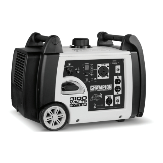
Champion 75537i Manual
Relay starter repair/replace
Hide thumbs
Also See for 75537i:
- Owners manual and operation instructions (33 pages) ,
- Owner's manual & operating instructions (33 pages) ,
- Technical bulletin (9 pages)
Advertisement
Quick Links
This covers the following models (Read completely before performing service):
• 75537i, 100204, 100261, 100262, 100263, 100264, 100477 – Dual Fuel, Electric Start, or Wireless
Remote Start
*Specification, descriptions and illustrations are as accurate as known at the time of publication but are subject
to change without notice.
SAFETY PRECAUTIONS
• To reduce the risk of injury, user must read and understand the operator's manual before using
this product.
• DO NOT make any adjustments to the generator without first stopping the engine, turning all
switches to the 'OFF' position, close fuel valve and disconnecting the spark plug wire.
• Burns from hot parts — let the engine cool for 30 minutes before touching hot parts.
• Injury from moving parts
• To reduce the possibility of fire or explosion, be careful when working around gasoline.
Keep cigarettes, sparks and flames away from all fuel‐related parts.
Phillips Screwdriver
Crescent Wrenches
Empty Gas Container
Nitrile Gloves
*3 – Containers or boxes for Parts
*Containers or boxes will help organize/identify parts when reassembling.
Never store the machine with gasoline in the fuel tank in a confined area with improper ventilation. Gasoline
fumes could reach open flames, sparks and cigarettes etc.
Relay Starter Repair/Replace
Tool
Rachet
Sockets
Pliers
Tools Required
7mm, 8mm, 10mm,
Size
3/8
Box nose
#2
7mm, 8mm
Minimum 2 Gallon
Small to Medium
Date: 5/8/2019
Advertisement

Related Manuals for Champion 75537i


Summary of Contents for Champion 75537i
- Page 1 Date: 5/8/2019 This covers the following models (Read completely before performing service): • 75537i, 100204, 100261, 100262, 100263, 100264, 100477 – Dual Fuel, Electric Start, or Wireless Remote Start *Specification, descriptions and illustrations are as accurate as known at the time of publication but are subject to change without notice.
- Page 2 1. Ensure that the Fuel Valve, Battery and Start switches are all in the “OFF” positions. (panel illustrated is from model 75537i) 2. Remove the 2 Phillips screws from the battery maintenance cover and pull on the rubber tab to access the battery.
- Page 3 3. Remove the 2 Philips screws to remove access panel. 4. Gently pull the spark plug cap by firmly grasping the spark plug insulator at the base. Leave disconnected while working on unit.
- Page 4 5. Remove the clear or pink carburetor drain hose from the drain hole in the base of the enclosure and extend hose to exterior and direct the hose into your gasoline container. Turn main fuel valve to the “ON” (“gasoline” position for Dual Fuel) and with hose securely positioned into your gasoline can loosen drain screw only enough until you see gas...
- Page 5 8. Located on the right side of the metal frame, remove the 2 bolts with a rachet and 10mm socket. *Put all parts into a box and label it “Right Side Parts” 9. With a Phillips screwdriver, remove the 2 screws on each side and then with a rachet with a 10mm socket, remove the 2 shoulder bolts at the bottom.
- Page 6 11. Unscrew gas cap and remove the Phillips screw. Place gas cap to the side. *We suggest you thread the screw back into the cap so as not to misplace. 12. Remove the top cover by removing the 4 bolts (2 on each side) with 10mm socket. *Put all parts into box labeled “Top/Handel Parts”...
- Page 7 14. Remove the 4 fuel tank bolts with 7mm socket. Remove the rubber hose on the top by gently twisting and pulling with your fingers. *Put all parts into a box labeled “Top/Handle Parts”. 15. Gently lift-up on the gas tank and locate the hose clamp securing the fuel line in place.
- Page 8 16. Loosen the choke cable clamp screw and loosen the cable wire clamp using a 7mm and 8mm wrench. Remove choke cable from Pinch bolt and allow cable to lay loosely so we can remove front panel in later step. 17.
- Page 9 18. Front panel remove the (5) screws as indicated. Remove the center screw and pull off fuel knob and place to the side. DO NOT lose the small center screw. *Put all parts into a box and label it “Front Panel” 19.
- Page 10 21. Located on the inside left front panel below the recoil cord, disconnect the Molex connector from the Rectifier. This will enable you to achieve more room to open the front panel. Exposed starting solenoid wire 22. Directly in front of you, against the engine block, you will see the starter solenoid and starter motor.
- Page 11 Reverse steps for reassembly. If you have any questions regarding these recommendations, please contact our technical department Monday‐Friday from 8:30 AM‐5:00 PM PST at 877‐338‐0999. Champion Power Equipment, Inc. 12039 Smith Ave. Santa Fe Springs, CA 90670 Phone: 1‐877‐338‐0999 Email: tech@championpowerequipment.com...
Need help?
Do you have a question about the 75537i and is the answer not in the manual?
Questions and answers