
Related Manuals for Wilo Atmos GIGA-N


Summary of Contents for Wilo Atmos GIGA-N
- Page 1 Pioneering for You Wilo-Atmos GIGA-N en Installation and operating instructions · 6074707 • Ed.01/2019-04...
-
Page 3: Table Of Contents
6 Installation and electrical connection .......................... 16 Personnel qualifications.................................... 16 Operator responsibilities.................................... 16 Preparing the installation.................................... 16 Setting up the pump by itself (variant B, Wilo variant key) ........................ 16 Installing the pump unit on a base ................................ 17 Pipework........................................... 18 Aligning the unit...................................... 19 Electrical connection ...................................... - Page 4 11 Spare parts.................................... 37 11.1 Spare parts list ......................................... 37 12 Disposal.................................... 38 12.1 Oils and lubricants...................................... 38 12.2 Water-glycol mixture ..................................... 38 12.3 Protective clothing ...................................... 38 12.4 Information on the collection of used electrical and electronic products.................... 38 WILO SE 2019-04...
-
Page 5: General Information
▪ Safety instructions relating to property damage start with a signal word and are dis- played without a symbol. CAUTION Type and source of the danger! Consequences or information. Signal words ▪ DANGER! Failure to observe the safety instructions will result in serious injuries or death! Installation and operating instructions Wilo-Atmos GIGA-N... -
Page 6: Personnel Qualifications
Personnel must have the following qualifications: ▪ Electrical work: A qualified electrician must carry out the electrical work. ▪ Installation/dismantling must be carried out by a qualified technician who is trained in the use of the necessary tools and fixation materials. WILO SE 2019-04... -
Page 7: Electrical Work
▪ Make sure that there is no risk of explosion when carrying out any type of welding work or work with electrical devices. During operation ▪ Wear protective equipment: – Safety shoes – Safety helmet (when using lifting equipment) Installation and operating instructions Wilo-Atmos GIGA-N... -
Page 8: Maintenance Tasks
Ensure that a dry run of the pump is not possible. A dry run can damage the shaft seal and thereby cause leakages. Maintenance tasks ▪ Wear the following protective equipment: – Sealed safety goggles – Safety shoes – Safety gloves for protection against cuts WILO SE 2019-04... -
Page 9: Drive: Iec Standard Motor
18 must be supervised by a technician. Application/use Intended use The glanded pumps in the Wilo-Atmos GIGA-N series are intended for use as circulators in building services. The Wilo-Atmos GIGA-N pumps may only be used for: ▪ Hot-water heating systems ▪... -
Page 10: Product Description
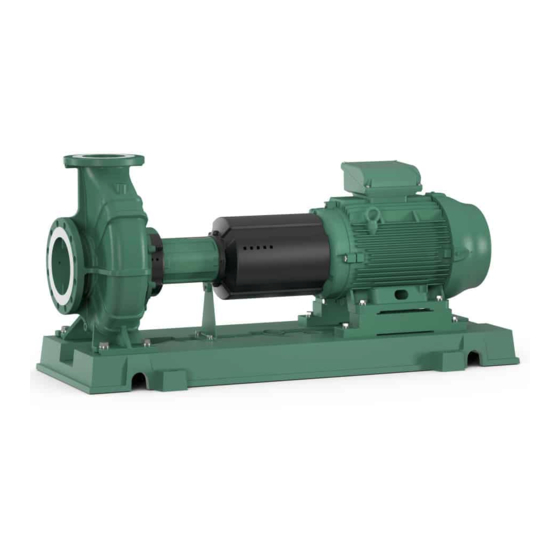
Product description Design The Wilo-Atmos GIGA-N pump is a single-stage back pull-out-centrifugal pump with spiral housing for horizontal installation. Power and dimensions in accordance with EN 733. Suitable Wilo control devices (e.g. Comfort control system, CC-HVAC) can control the power of the pumps continuously. -
Page 11: Type Key
Accessories have to be ordered separately. For a detailed list, consult the catalogue and spare parts documentation. Anticipated noise levels 4.7.1 Pump with three-phase motor, 50 Hz without speed control Motor power P [kW] Measuring surface sound-pressure level Lp, A [dB(A)] 2-pin (2900 rpm) 4-pin (1450 rpm) – 0.37 0.55 Installation and operating instructions Wilo-Atmos GIGA-N... - Page 12 Table 1: Anticipated noise levels for standard pump (50 Hz) 4.7.2 Pump with three-phase motor, 60 Hz without speed control Motor power P [kW] Measuring surface sound-pressure level Lp, A [dB(A)] 2-pin (2900 rpm) 4-pin (1450 rpm) – 0.37 0.55 0.75 18.5 WILO SE 2019-04...
-
Page 13: Permissible Forces And Torques On The Pump Flanges
1243 1120 2170 1068 1750 1575 1418 2748 1278 2345 2100 1890 3658 1138 1680 Values in acc. with ISO/DIN 5199 – class II (2002) – Appendix B, Family no. 1A. Table 3: Permissible forces and torques on the pump flanges Installation and operating instructions Wilo-Atmos GIGA-N... -
Page 14: Transportation And Storage
Use only properly functioning lifting equipment to lift and lower the pump. Ensure that the pump does not become jammed during lifting and lowering. Do not exceed the maximum bearing capacity of the lifting equipment! Check that lifting equip- ment is functioning properly before use! WILO SE 2019-04... - Page 15 If necessary, use a lifting arm, to which the lift- ing gear can be vertically attached. ▪ Ensure the load is lifted vertically! ▪ Prevent the suspended load from swinging! Installation and operating instructions Wilo-Atmos GIGA-N...
-
Page 16: Storage
▪ Mount the pump in a readily accessible place. This makes it easier to complete inspec- tions, maintenance (e.g. mechanical seal change) or replacement in the future. ▪ A travelling crane or a device for attaching hoisting gear should be installed above the set-up site of large pumps. WILO SE 2019-04... -
Page 17: Setting Up The Pump By Itself (Variant B, Wilo Variant Key)
The base must be able to support the unit installed on the baseplate indefinitely. The base must be level to ensure there is no tension on the baseplate or unit. Wilo recom- mends using premium, non-shrink concrete of an adequate thickness for manufactur- ing. - Page 18 This allows the screws to be moved in order to achieve their final positions. Wilo recommends initially pouring the base up to about 25 mm below the planned height. The surface of the concrete base must be well contoured before curing. Remove the pipe sleeves after the concrete cures.
-
Page 19: Pipework
Changes to the alignment during operation can result in property dam- age. The pump and motor are usually aligned at ambient temperature. Thermal expansion at operating temperature can change the alignment, particularly in the case of very Installation and operating instructions Wilo-Atmos GIGA-N... - Page 20 (with speed n in rpm, DA in mm, radial displacement ΔKr in mm) perm. Coupling size DA [mm] S [mm] S2 [mm] 2 ... 4 2 ... 4 2 ... 4 2 ... 4 2 ... 4 2 ... 4 2 ... 6 2 ... 6 WILO SE 2019-04...
- Page 21 The axial deviation of the two coupling halves must not exceed the maximum values found in table “Permissible gaps S and S2”. This requirement applies to every oper- ating status – including operating temperature and inlet pressure. Installation and operating instructions Wilo-Atmos GIGA-N...
- Page 22 ▪ Finally, check the function of the coupling and shaft. The coupling and shaft must be easy to turn by hand. ▪ After correct alignment, mount the coupling guard. The tightening torques for the pump and motor on the baseplate are listed in the table “Tightening torques for pump and motor”. WILO SE 2019-04...
-
Page 23: Electrical Connection
Cables must be bent off to form outlet loops near screwed connections to avoid the ac- cumulation of drip water. ▪ Unused cable feedthroughs should be sealed with the sealing plates provided, and screwed tight. ▪ Reinstall any uninstalled safety devices, such as terminal box covers! Installation and operating instructions Wilo-Atmos GIGA-N... -
Page 24: Commissioning
• The pump must not be operated outside of the specified operating range. • Do not operate the pump with the shut-off devices closed. • Make sure that the NPSH-A value is always higher than the NPSH-R value. WILO SE 2019-04... -
Page 25: Personnel Qualifications
Filling and venting NOTICE The standard version of the Atmos GIGA-N pump has no air vent valve. The suction line and pump are vented via a suitable venting device on the pressure flange of the pump. An optional air vent valve is available. -
Page 26: Switching On The Pump
▪ While the pump is starting, vent completely via the venting screw. CAUTION Risk of property damage! If abnormal noises, vibrations, temperatures or leaks occur when starting up: • Switch the pump off immediately and remedy the cause. WILO SE 2019-04... -
Page 27: Switching Frequency
▪ Spray the interior of the pump with a preservative through the suction and discharge ports. ▪ Close the suction and discharge ports with caps. ▪ Grease or oil the blank components. For this, use silicone-free grease or oil. Observe the manufacturer’s instructions for preservatives. Installation and operating instructions Wilo-Atmos GIGA-N... -
Page 28: Maintenance/Repair
Maintenance/repair Maintenance/repair It is recommended to have the pump serviced and checked by the Wilo customer ser- vice. Maintenance and repair work require the pump be partially or completely dismantled. The pump housing can be installed in the piping. DANGER... -
Page 29: Maintenance Tasks
Maintenance/repair ▪ Wilo recommends briefly putting the standby pumps into operation at least once a week to ensure they are always ready for operation. Maintenance tasks The bearing bracket of the pump is equipped with roller bearings that have lifetime lub- rication. - Page 30 6. Remove the hexagon head screws (7.2) and remove the protective grid (7.1). 7. Loosen the impeller nut (2.2) and remove along with the lock washer and impeller disc. Version with mechanical seal (optional: mechanical seal on the sleeve) Fig. 21: Version with mechanical seal WILO SE 2019-04...
- Page 31 If the volume flow decreases and the motor shows signs of in- creased current consumption, this could be caused by an impermissibly high gap back- lash. In this case, replace the neck rings. Installation and operating instructions Wilo-Atmos GIGA-N...
-
Page 32: Installation
3. Insert the retaining rings (4.4) into the groove and the bearing cover (4.2) into the drilled hole of the bearing bracket (5). 4. Push the V-gaskets (4.3) and thrower (4.2) onto the shaft (3.1). 5. Insert the key (3.3) into the shaft nut. WILO SE 2019-04... - Page 33 4. Screw the housing cover (10) onto the bearing bracket with the interior hexagonal head screws (15). 5. Push the rotating part of the mechanical seal (9.1) onto the shaft (optional: sleeve). 6. Push the spacer (9.2) onto the shaft. Installation and operating instructions Wilo-Atmos GIGA-N...
-
Page 34: Faults, Causes And Remedies
Risk of death due to electrocution! Improper conduct when carrying out electrical work can lead to death due to electric shock! Electrical work must be carried out by a qualified electrician in accordance with the locally applicable regulations. WILO SE 2019-04... -
Page 35: Faults
– Minimise resistances too high in the suction line – Clean filter – Reduce negative suc- tion head by installing the pump lower Sealing gap too large – Exchange worn neck due to wear ring Installation and operating instructions Wilo-Atmos GIGA-N... - Page 36 – Rebalance the im- peller peller Bearing damage – Exchange bearing Foreign object in the – Clean pump pump Pump pumps against – Open the shut-off closed shut-off device device in the pressure pipe Table 11: Causes of error and remedies WILO SE 2019-04...
-
Page 37: Spare Parts
Spare parts Spare parts Spare parts may be ordered via a local installer and/or Wilo customer service. List of ori- ginal spare parts: Refer to the Wilo spare parts documentation and the following in- formation in these installation and operating instructions. -
Page 38: Disposal
Disposal in domestic waste is forbidden! In the European Union, this symbol can appear on the product, the packaging or the accompanying documentation. It means that the electrical and electronic products in question must not be disposed of along with domestic waste. WILO SE 2019-04... - Page 39 Further recycling informa- tion at www.salmson‑recycling.com. Please consult your local municipality, the nearest waste disposal site, or the dealer who sold the product to you for information on proper disposal. Further recycling informa- tion at www.wilo‑recycling.com. Installation and operating instructions Wilo-Atmos GIGA-N...
- Page 43 WILO Pompa Sistemleri Jakarta Timur, 13950 Sistemas Hidraulicos Lda. San. ve Tic. A.S¸ T +62 21 7247676 4475-330 Maia 34956 İstanbul citrawilo@cbn.net.id T +351 22 2080350 T +90 216 2509400 bombas@wilo.pt wilo@wilo.com.tr Further subsidiaries, representation and sales offices on www.wilo.com Oktober 2018...
- Page 44 WILO SE Nortkirchenstr. 100 44263 Dortmund Germany T +49 (0)231 4102-0 T +49 (0)231 4102-7363 wilo@wilo.com Pioneering for You www.wilo.com...
Need help?
Do you have a question about the Atmos GIGA-N and is the answer not in the manual?
Questions and answers