Xray NT1 Set-Up Book
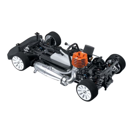
1/10 luxury nitro touring car
Hide thumbs
Also See for NT1:
- Instruction manaul (41 pages) ,
- Instruction manual (49 pages) ,
- Instruction manual (52 pages)
Table of Contents
Advertisement
Quick Links
Advertisement
Table of Contents

Subscribe to Our Youtube Channel
Related Manuals for Xray NT1


Summary of Contents for Xray NT1
- Page 1 ®...
-
Page 2: Table Of Contents
Foam Tire Tips Bearing Maintenance Martin Hudy, Junior Designer at XRAY R&D, guides you through the set-up theory of the XRAY NT1 and discloses all the tips & tricks to make your NT1 a winning car. All texts and images contained within this set-up book are copyright by XRAY. All rights reserved. ©2007 XRAY... -
Page 3: Setting Up The Xray Nt1
If you choose to adjust the setup of your NT1, make small adjustments one at a time, and see if you fi nd any improvement in performance and/or handling with each adjustment. We advise you to keep track of your setup changes, and record which setups work best at different racetracks under various conditions. -
Page 4: Set-Up Order
We recommend setting up your NT1 chassis in the order indicated in the table below. The order of the chassis settings has been determined as the most logical to set up your NT1 chassis properly and easily. Also, certain chassis settings must be made before others, as changing one setting will impact another setting. -
Page 5: Weight Transfer
WEIGHT TRANSFER WEIGHT TRANSFER Weight transfer is the key to car handling. Consider that a car has a certain amount of “weight” on various parts of the car and this weight is distributed by a certain amount into each wheel. •... -
Page 6: Effects Of Downstop Adjustment
DOWNSTOPS EFFECTS OF DOWNSTOP ADJUSTMENT Front Downstops Higher front • Decreases front chassis upward travel on-throttle. downstop value • Increases high-speed steering. • Increases “initial” on-throttle understeer. • Better on smooth tracks. Lower front • Increases upward chassis travel on-throttle. downstop value •... -
Page 7: Adjusting Downstops
DOWNSTOPS REAR DOWNSTOPS Measure at the bottom of the rear uprights. Do NOT measure under the arm. Droop Gauge Values • Positive numbers on the gauge indicate the distance (in mm) ABOVE the top level of the elevating blocks (or, above the bottom of the chassis). •... -
Page 8: Shock Absorbers
“harder” since it will be more diffi cult to compress than a spring with a lower “spring weight” number. XRAY shock springs are color-coded so that all springs of a specifi c “spring weight” have the same external colour. Note that spring colours are NOT standardized;... -
Page 9: Shock Spring Preload
SHOCK ABSORBERS SHOCK SPRING PRELOAD PRELOAD SETTING THREADED PRELOAD COLLAR Increase TIGHTEN collar so it moves DOWN the shock body. Hint: File a small notch on the top of each spring collar so Decrease LOOSEN collar so it moves UP the shock body. you can tell when you have adjusted it one full rotation. -
Page 10: Shock Damping
Shock oil with a higher viscosity (for example, 300cSt oil) is thicker than shock oil with a lower viscosity (for example, 150cSt oil). We recommend using only highest-grade XRAY Silicone Shock Oil, which is available in numerous viscosities. XRAY Silicone Shock Oil is specially formulated to be temperature-resistant and low-foaming for use in XRAY shocks. -
Page 11: Adjusting Shock Damping
SHOCK ABSORBERS Adjusting with... Effect Shock Oil Piston Holes REAR SHOCKS • Slower steering response. Thinner More holes • Decreases rear grip at corner exit/under acceleration. Softer damping • Increases rear grip under braking. • Slower steering response. Harder damping Thicker Less holes •... -
Page 12: Effects Of Track-Width Adjustment
TRACK-WIDTH EFFECTS OF TRACK-WIDTH ADJUSTMENT • Decreases front grip. • Increases understeer. Wider • Slower steering response. • Use to avoid traction rolling. FRONT TRACK-WIDTH • Increases front grip. Narrower • Decreases understeer. • Faster steering response. • Increases rear grip at corner entry. Wider •... -
Page 13: Ride Height
RIDE HEIGHT ADJUSTING REAR TRACK-WIDTH Adjust rear track-width using the two (2) lower pivotballs in the rear hubs, and also the rear upper camber link: • INCREASE rear track-width (wider): Turn OUT (CCW) both lower pivotballs equally, and lengthen the rear upper camber link. -
Page 14: Adjusting Ride Height
RIDE HEIGHT 3. Measure the ride height using the ride height gauge at the front and rear of the car at the lowest points of the chassis. ADJUSTING RIDE HEIGHT Adjust ride height using spring preload only. DO NOT adjust ride height using the downstop setscrews. PRELOAD SETTING THREADED PRELOAD COLLAR Increase... -
Page 15: Measuring Camber
CAMBER MEASURING CAMBER INITIAL STEPS SET-UP COMPONENTS Prepare the car as follows: Use the following set-up components: • Shocks: Attach the front and rear shocks. • Anti-roll bars: Detach front and rear anti-roll bars. • assembled set-up stands • Wheels: Remove the wheels. 1. -
Page 16: Caster
CASTER ADJUSTING REAR CAMBER Adjust rear camber using the rear upper camber link; DO NOT adjust the rear lower pivotballs. • MORE NEGATIVE rear camber (more inclined): SHORTEN the rear upper camber link. • LESS NEGATIVE rear camber (more upright): LENGTHEN the rear upper camber link. -
Page 17: Adjusting Caster
ADJUSTING CASTER Adjust caster by installing different-thickness caster clips behind the front upper arm (on the pivot pin). IMPORTANT: Make sure you adjust caster so it is equal on both left and right sides. Caster angle may be adjusted by using different thicknesses of spacers ahead of and behind the upper front arm. -
Page 18: Adjusting Toe
PREPARING TO MEASURE TOE 1. Assemble the set-up stands. 2. Mount the set-up stands on the axles. 3. Place the car on the set-up board. MEASURING FRONT TOE 1. With the car in the set-up system, set the toe gauge atop the front set-up stands. The pins at the top of the stands fi... -
Page 19: Anti-Roll Bars
ADJUSTING REAR TOE Adjust rear toe using the 2 lower pivotballs in each rear upright; the pivotballs must be adjusted in equal but opposite directions. • MORE rear toe-in (rear tires point in more): Turn IN the forward lower pivotball, and turn OUT the rearward lower pivotball equally •... -
Page 20: Tweak
ANTI-ROLL BARS ADJUSTING THE REAR ANTI-ROLL BAR Adjust the rear anti-roll bar by moving the linkage upper pivotball on the bar: • SOFTER rear anti-roll bar: Move the linkage upper pivotball outward towards the end of the bar. • STIFFER rear anti-roll bar: Move the linkage upper pivotball inward away from the end of the bar. -
Page 21: Measuring & Correcting Tweak
TWEAK MEASURING & CORRECTING TWEAK Measure and correct chassis tweak by fi rst adjusting shock preload, and then by adjusting the anti-roll bars. INITIAL STEPS SET-UP COMPONENTS Prepare the car as follows: Use the following set-up components: • Shocks: Attach the shocks •... - Page 22 TWEAK CORRECTING FRONT TWEAK – STEP 1: SHOCK PRELOAD Determine if the FRONT of the car is tweaked by checking at the REAR of the car. Correct front suspension tweak by adjusting preload on the REAR shock springs. 1. Lift and drop the front and rear ends of the car a few cm’s to let the suspension settle. 2.
-
Page 23: Xca Clutch
Thrustbearing Collar The XCA (XRAY Centrifugal-Axial) Clutch must be properly set up before driving the car the fi rst time. A properly set up clutch will have a dramatic impact on the performance and drivability of the NT1. It is important to note that there are many factors that may affect engine and clutch performance. Factors such as proper engine tuning, proper clutch assembly, clutch gap, and clutch endplay can all affect clutch performance. -
Page 24: Flywheel Shimming
XCA CLUTCH FLYWHEEL SHIMMING When installing the XCA Clutch on the engine crankshaft, the fl ywheel must be properly shimmed outward from the engine so the crankshaft protrudes the proper amount. This will affect other adjustments such as clutch spring preload, clutch gap, and clutchbell endplay. -
Page 25: Clutch Gap
XCA CLUTCH CLUTCH GAP Clutch gap is the amount that the clutch shoe moves before it contacts the clutchbell. This affects the WAY that the clutch engages more than WHEN it engages. Clutch gap must be adjusted BEFORE clutchbell endplay, and is done with only the outermost (smaller) ball-bearing and thrustbearing assembly installed;... -
Page 26: Adjusting Clutchbell Endplay
2-speed shoes onto the layshaft, thereby re-engaging 1st gear. The 2-speed transmission in the XRAY NT1 may be adjusted for shift point and shoe gap: • Shift-point screws determine when the transmission shifts between 1st and 2nd gear •... -
Page 27: Adjusting Shift Point
2-SPEED TRANSMISSION Earlier shift point • 2nd gear engages earlier (looser screws) • Lower engine RPM and engine tone before 2nd gear engages • 2nd gear engages later Later shift point (tighter screws) • Higher engine RPM and engine tone before 2nd gear engages ADJUSTING SHIFT POINT Shift-point Screws –... -
Page 28: Multi-Flex Technology
The optional MFT™ 1-piece engine mounting system for the NT1 allows you to set up and adjust the NT1 chassis stiffness in the engine bay to suit various racing conditions or driving styles. The standard 2-piece engine mount was designed and tested to allow the right amount of chassis fl... -
Page 29: Roll Center
ROLL CENTER ROLL CENTER A “roll center” is a theoretical point around which the chassis rolls, and is determined by the design of the suspension. Front and rear suspensions normally have different roll centers. The “roll axis” is the imaginary line between the front and rear roll centers. -
Page 30: Adjusting Roll Center
ADJUSTING ROLL CENTER Adjusting the front or rear roll center on the NT1 is the best way to change mid-corner grip at either end of the car, as well as to balance out the overall grip between the front and rear. - Page 31 ROLL CENTER FINE REAR ROLL CENTER ADJUSTMENTS Make fi ner adjustment to rear roll center by changing the rear upper camber link mounting positions. REAR ROLL CENTER TOWER (camber link inner mounting positions) Lower holes (inner or outer) Higher rear roll center Upper holes (inner or outer) Lower rear roll center...
-
Page 32: Camber Rise
Also referred to as “camber intake,” this measurement quantifi es how much the camber changes on the car when the suspension is compressed. Rear camber rise on the NT1 is adjustable via the rear upper camber link, by changing its inner and outer mounting locations, as well as length. -
Page 33: Steering Ackermann
The size and geometry of the servo saver on XRAY cars forces the inside wheel to increase its turning angle at a greater rate than the outside wheel, as the servo turns either way from center. -
Page 34: Front And Rear Axles
FRONT & REAR AXLES FRONT AND REAR AXLES The XRAY NT1 comes standard with a single choice for rear axle, and 2 options for front axle. The choice of front axle depends on track conditions and driving style. Front Axles: Rear Axle: •... -
Page 35: Solid Front Axle
XRAY MULTI-DIFF™ The optional XRAY Multi-Diff™ may be used in the NT1, and be quickly and easily confi gured to be one of three different types of front axle: front solid axle, front solid one-way, and also a front one-way. -
Page 36: Gearing
“pulls” its way out of corners. In order to accelerate the process of dialing your NT1 at a track that you have never raced at, you should ask drivers who are familiar with the track about their rollout and overdrive. -
Page 37: Final Drive Ratio (Fdr)
Rollout is calculated using the circumference of a tire. Since the NT1 uses foam tires, as the foam tires wear and get smaller, the rollout value changes a lot more quickly. -
Page 38: Shock Building Tips
TIPS SHOCK BUILDING TIPS COMPOSITE PARTS PREPARATION Carefully use a hobby knife (at a perpendicular angle) or fi ne fi le to gently remove excess composite material from the outer edge of each piston. This is a critical step; the outer edges of the shock pistons must be smooth and round. -
Page 39: Foam Tire Tips
BEARING MAINTENANCE DRIVETRAIN BALL-BEARINGS The following procedures are recommended to clean all of the drivetrain ball-bearings in your NT1. For high-competition racing, we recommended doing this every 3-4 weeks, or before a major event. Remove the blue seals on both sides of the bearing by inserting the tip of a hobby knife into the inner seam and prying the seal up and out. - Page 40 PHONE: 214-744-2400, FAX: 214-744-2401, xray@rcamerica.com PHONE: 214-744-2400, FAX: 214-744-2401, xray@rcamerica.com ALL RIGHTS RESERVED. © XRAY. ALL ARTWORK & DESIGN BY XRAY. ALL RIGHTS RESERVED. © XRAY. ALL ARTWORK & DESIGN BY XRAY. ALL RIGHTS RESERVED. © XRAY. ALL ARTWORK & DESIGN BY XRAY.
Need help?
Do you have a question about the NT1 and is the answer not in the manual?
Questions and answers