
Related Manuals for YASKAWA GA50U Series


Summary of Contents for YASKAWA GA50U Series
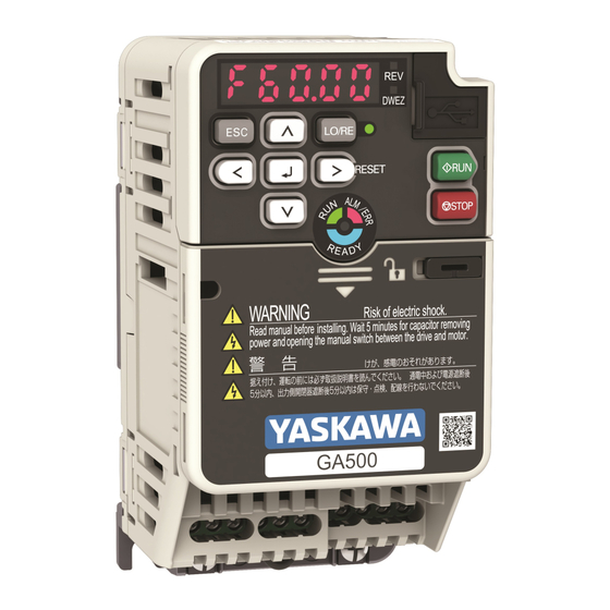
- Page 1 GA500 Industrial AC Microdrive Installation & Primary Operation Catalog Code: GA50Uxxxxxxxx 240 V Single-Phase Input: 1/6 to 5 HP 240 V Three-Phase Input: 1/6 to 30 HP 480 V Three-Phase Input: 1/2 to 40 HP...
- Page 2 This Page Intentionally Blank YASKAWA TOEPC71061752B GA500 Drive Installation & Primary Operation...
-
Page 3: Table Of Contents
Motor and Main Circuit Connections ......... . 51 YASKAWA TOEPC71061752B GA500 Drive Installation & Primary Operation... - Page 4 Auto-Tuning Errors ............126 YASKAWA TOEPC71061752B GA500 Drive Installation & Primary Operation...
- Page 5 WEEE Directive ............195 YASKAWA TOEPC71061752B GA500 Drive Installation & Primary Operation...
- Page 6 Revision History ............196 YASKAWA TOEPC71061752B GA500 Drive Installation & Primary Operation...
-
Page 7: General Information
In all cases, Yaskawa products should not be incorporated into a product or design as the exclusive or sole safety control function. All control functions are designed to dynamically detect failures and operate safely without exception. - Page 8 OFF. Then check the wiring and peripheral device ratings to find the cause of the problem. If you do not know the cause of the problem, contact Yaskawa before you energize the drive or peripheral devices.
-
Page 9: Warranty Information
• This product is not designed and manufactured for use in life-support machines or systems. • Contact a Yaskawa representative or your Yaskawa sales representative if you are considering the application of this product for special purposes, such as machines or systems used for passenger cars, medicine, airplanes and aerospace, nuclear power, electric power, or undersea relaying. - Page 10 • Installing the drive between 2000 m to 4000 m (6562 ft to 13123 ft) and grounding the neutral point on the power supply. Contact Yaskawa or your nearest sales representative when not grounding the neutral point. • 10 Hz to 20 Hz: 1 G (9.8 m/s , 32.15 ft/s...
- Page 11 Main speed frequency reference: -10 Vdc to +10 Vdc (minimum 15 kΩ), 0 Vdc to 10 Vdc (minimum Frequency 15 kΩ), 4 mA to 20 mA (250 Ω), 0 mA to 20 mA (250 Ω) Setting Signal Main speed reference: Pulse train input (maximum 32 kHz) YASKAWA TOEPC71061752B GA500 Drive Installation & Primary Operation...
- Page 12 Control (with Sleep Function), Energy Saving Control, MEMOBUS/Modbus Communications (RS- 485 max, 115.2 kbps), Auto Restart, Application Presets, DriveWorksEZ (customized functions), Parameter Backup Function, Online Tuning, KEB, Overexcitation Deceleration, Overvoltage Suppression, High Frequency Injection, etc. YASKAWA TOEPC71061752B GA500 Drive Installation & Primary Operation...
-
Page 13: Moving The Drive
“C/C” section of the drive nameplate to make sure that you received the correct model. Contact your supplier or Yaskawa sales office if you received an incorrect drive model or if the drive does not operate correctly. -
Page 14: How To Read The Catalog Code
F - Enclosure protection design Figure 5.1 Nameplate Information Example ◆ How to Read the Catalog Code Use the information in Figure 5.2 Table 5.1 to read the drive catalog code. YASKAWA TOEPC71061752B GA500 Drive Installation & Primary Operation... -
Page 15: Rated Output Current
• Derate the output current in applications that: –Increase the carrier frequency –Have high ambient temperature –Install drives side-by-side • Use C6-01 [Normal / Heavy Duty Selection] to select Normal Duty rating (ND) or Heavy Duty rating (HD). YASKAWA TOEPC71061752B GA500 Drive Installation & Primary Operation... - Page 16 25.0 7.5 (10) 30.0 2042 7.5 (10) 33.0 11.0 (15) 42.0 2056 11.0 (15) 47.0 15.0 (20) 56.0 2070 15.0 (20) 60.0 18.5 (25) 70.0 2082 18.5 (25) 75.0 22.0 (30) 82.0 YASKAWA TOEPC71061752B GA500 Drive Installation & Primary Operation...
- Page 17 18.0 11.0 (15) 23.4 4031 11.0 (15) 24.0 15.0 (20) 31.0 4038 15.0 (20) 31.0 18.5 (25) 38.0 4044 18.5 (25) 39.0 22.0 (30) 44.0 4060 22.0 (30) 45.0 30.0 (40) 60.0 YASKAWA TOEPC71061752B GA500 Drive Installation & Primary Operation...
-
Page 18: Overview Of Keypad Components And Functions
• REMOTE: Use the control circuit terminal or serial transmission to operate the drive. Use the frequency reference source entered in b1-01 and the Run command source selected in b1-02. YASKAWA TOEPC71061752B GA500 Drive Installation & Primary Operation... - Page 19 • Selects each mode, parameter, and set value. • Goes back to the previous screen. ESC Key • Push and hold to go back to the frequency reference screen (the initial screen). YASKAWA TOEPC71061752B GA500 Drive Installation & Primary Operation...
- Page 20 REMOTE Run Selection = Accept Existing RUN Command], the drive can start suddenly. Before you change the control source, remove all personnel from the area around the drive, motor, and load. Sudden starts can cause serious injury or death. YASKAWA TOEPC71061752B GA500 Drive Installation & Primary Operation...
-
Page 21: Keypad Mode And Menu Displays
6 Overview of Keypad Components and Functions ◆ Keypad Mode and Menu Displays Figure 6.2 Keypad Functions and Display Levels YASKAWA TOEPC71061752B GA500 Drive Installation & Primary Operation... -
Page 22: Mechanical Installation
(5.04) (2.99) (2.20) (0.24) (4.65) (0.20) (0.26) (0.12) (1.1) B002A (2.68) (5.04) (2.99) (2.20) (0.24) (4.65) (0.20) (0.26) (0.12) (1.1) 38.5 B004A (2.68) (5.04) (4.65) (2.20) (0.24) (4.65) (0.20) (1.52) (0.20) (1.8) YASKAWA TOEPC71061752B GA500 Drive Installation & Primary Operation... - Page 23 (4.57) (2.20) (0.24) (4.65) (0.20) (0.26) (0.12) (1.3) 38.5 2004E (2.68) (5.04) (5.83) (2.20) (0.24) (4.65) (0.20) (1.52) (0.20) (2.0) 58.5 2006E (2.68) (5.04) (6.61) (2.20) (0.24) (4.65) (0.20) (2.30) (0.20) (2.4) YASKAWA TOEPC71061752B GA500 Drive Installation & Primary Operation...
- Page 24 (5.04) (7.19) (3.78) (0.24) (4.65) (0.20) (2.22) (0.20) (4.0) 56.5 B010E (4.25) (5.04) (7.83) (3.78) (0.24) (4.65) (0.20) (2.22) (0.20) (4.0) B012E (5.51) (5.04) (7.99) (5.04) (0.24) (4.65) (0.20) (2.56) (0.20) (6.0) YASKAWA TOEPC71061752B GA500 Drive Installation & Primary Operation...
- Page 25 (5.04) (6.06) (3.78) (0.24) (4.65) (0.20) (2.22) (0.20) (3.3) 56.5 4009A (4.25) (5.04) (6.06) (3.78) (0.24) (4.65) (0.20) (2.22) (0.20) (3.3) 4012A (5.51) (5.04) (5.63) (5.04) (0.24) (4.65) (0.20) (2.56) (0.20) (4.4) YASKAWA TOEPC71061752B GA500 Drive Installation & Primary Operation...
- Page 26 (5.04) (7.83) (3.78) (0.24) (4.65) (0.20) (2.22) (0.20) (4.2) 4012E (5.51) (5.04) (7.60) (5.04) (0.24) (4.65) (0.20) (2.56) (0.20) (5.7) 2030 to 2082, 4018 to 4060 Figure 7.3 Exterior and Mounting Dimensions YASKAWA TOEPC71061752B GA500 Drive Installation & Primary Operation...
- Page 27 (5.51) (10.24) (5.51) (4.80) (0.35) (9.76) (0.24) (2.17) (0.20) (7.1) 4031A (7.09) (11.81) (5.63) (6.30) (0.39) (11.18) (0.31) (2.17) (0.20) (10.2) 4038A (7.09) (11.81) (5.63) (6.30) (0.39) (11.18) (0.31) (2.17) (0.20) (10.6) YASKAWA TOEPC71061752B GA500 Drive Installation & Primary Operation...
-
Page 28: Installation Position And Clearances
A - Vertical installation C - Rotated installation B - Horizontal installation Figure 7.4 Installation Orientation Refer to the drive Technical Reference (SIEP C710617 52) for more information about horizontal installation. YASKAWA TOEPC71061752B GA500 Drive Installation & Primary Operation... - Page 29 Install Drives Side-by-Side When you install drives side-by-side, set to L8-35 = 1 [Installation Method Selection = Side-by- Side Mounting]. Refer to the Technical Reference and derate the drives for the ambient temperature. YASKAWA TOEPC71061752B GA500 Drive Installation & Primary Operation...
-
Page 30: Removing/Reattaching Covers
Use a slotted screwdriver to unlock the front cover of the drive. Use a slotted screwdriver with a tip width of 2.5 mm (0.1 in) or less and a thickness of 0.4 mm (0.02 in) or less. YASKAWA TOEPC71061752B GA500 Drive Installation & Primary Operation... -
Page 31: Reattach The
Reattach the Front Cover Reverse the steps to reattach the cover. Note: Make sure that you do not pinch wires or signal lines between the front cover and the drive before you reattach the cover. YASKAWA TOEPC71061752B GA500 Drive Installation & Primary Operation... -
Page 32: Electrical Installation
WARNING Electrical Shock Hazard. Correctly ground the drive before you turn on the EMC filter switch. If you touch electrical equipment that is not grounded, it can cause serious injury or death. YASKAWA TOEPC71061752B GA500 Drive Installation & Primary Operation... -
Page 33: Standard Connection Diagram
Motor winding and insulation failure can occur. Note: Do not connect the AC control circuit ground to the drive enclosure. Failure to obey can cause incorrect control circuit operation. YASKAWA TOEPC71061752B GA500 Drive Installation & Primary Operation... - Page 34 L5-02 = 1 [Fault Contact at Restart Select = Always Active] to de- energize the drive. Be careful when you use a cut-off sequence. The default setting for L5-02 is 0 [Active Only when Not Restarting]. YASKAWA TOEPC71061752B GA500 Drive Installation & Primary Operation...
-
Page 35: Main Circuit Terminal Block Wiring Procedure
DC bus voltage decreases below 50 Vdc. When all indicators are OFF, measure for dangerous voltages to make sure that the drive is safe. If you do work on the drive when it is energized, it will cause serious injury or death from electrical shock. YASKAWA TOEPC71061752B GA500 Drive Installation & Primary Operation... -
Page 36: Wire To The Main Circuit Terminal Block
• If you use power tools to tighten the terminal screws, use a low speed setting (300 to 400 r/ min). Failure to obey can cause damage to the terminal screws. • Users can purchase wiring tools from Yaskawa. Contact Yaskawa or your nearest sales representative for more information. - Page 37 4.1 - 4.5 N∙m ≥ 30 mm (36.3 - 39.8 (AWG 8) *2 *3 in∙lb) 5 - 9 N∙m SF-BIT-HEX 5- PHOENIX (44.3 - 79.7 CONTACT *2 *3 (WAF: 5 mm) in∙lb) YASKAWA TOEPC71061752B GA500 Drive Installation & Primary Operation...
-
Page 38: Main Circuit Terminal Functions
There is a jumper between terminals +1 and +2. Remove the jumper, then wire to terminals +1 and +2. Tighten the screws to the specified torque. Figure 8.6 Tighten Terminal Block Screws ◆ Main Circuit Terminal Functions Refer to Table 8.2 for the functions of drive main circuit terminals. YASKAWA TOEPC71061752B GA500 Drive Installation & Primary Operation... -
Page 39: Wire Selection
These tables use icons in Table 8.3 to show the shapes of the screw heads. Table 8.3 Icons to Identify Screw Shapes Icon Screw Shape Slotted (-) Hex socket cap (WAF: 5 mm) YASKAWA TOEPC71061752B GA500 Drive Installation & Primary Operation... -
Page 40: Single-Phase 200 V Class
0.5 - 0.6 U/T1, V/T2, W/T3 (4.4 - 5.3) 0.5 - 0.6 B004 -, +1 (4.4 - 5.3) 0.5 - 0.6 B1, B2 (4.4 - 5.3) 0.8 - 1.0 M3.5 (7.1 - 8.9) YASKAWA TOEPC71061752B GA500 Drive Installation & Primary Operation... - Page 41 1.5 - 1.7 B012 -, +1 14 - 8 (13.5 - 15) 1.5 - 1.7 B1, B2 14 - 12 (13.5 - 15) 1.2 - 1.5 14 - 10 (10.6 - 13.3) YASKAWA TOEPC71061752B GA500 Drive Installation & Primary Operation...
- Page 42 10 mm (copper wire). • 8-4NS from JST Mfg. Co., Ltd. • R8-4S from NICHIFU Co.,Ltd. • P10-8R from PANDUIT Corp. YASKAWA TOEPC71061752B GA500 Drive Installation & Primary Operation...
-
Page 43: Three-Phase 200 V Class
0.5 - 0.6 U/T1, V/T2, W/T3 (4.4 - 5.3) 0.5 - 0.6 2004 -, +1, +2 (4.4 - 5.3) 0.5 - 0.6 B1, B2 (4.4 - 5.3) 0.8 - 1.0 M3.5 (7.1 - 8.9) YASKAWA TOEPC71061752B GA500 Drive Installation & Primary Operation... - Page 44 0.5 - 0.6 2012 -, +1, +2 12 - 10 (4.4 - 5.3) 0.5 - 0.6 B1, B2 14 - 12 (4.4 - 5.3) 1.2 - 1.5 14 - 10 (10.6 - 13.3) YASKAWA TOEPC71061752B GA500 Drive Installation & Primary Operation...
- Page 45 10 - 2 • AWG 8 ≤ 4.1 - 4.5 (36 - 40) 1.5 - 1.7 B1, B2 14 - 6 (13.5 - 15) 2.0 - 2.5 10 - 6 (17.7 - 22.1) YASKAWA TOEPC71061752B GA500 Drive Installation & Primary Operation...
- Page 46 10 mm (copper wire). • 8-4NS from JST Mfg. Co., Ltd. • R8-4S from NICHIFU Co.,Ltd. • P10-8R from PANDUIT Corp. YASKAWA TOEPC71061752B GA500 Drive Installation & Primary Operation...
-
Page 47: Three-Phase 400 V Class
0.5 - 0.6 4004 -, +1, +2 14 - 12 (4.4 - 5.3) 0.5 - 0.6 B1, B2 14 - 12 (4.4 - 5.3) 1.2 - 1.5 14 - 10 (10.6 - 13.3) YASKAWA TOEPC71061752B GA500 Drive Installation & Primary Operation... - Page 48 0.5 - 0.6 4009 -, +1, +2 14 - 12 (4.4 - 5.3) 0.5 - 0.6 B1, B2 14 - 12 (4.4 - 5.3) 1.2 - 1.5 14 - 10 (10.6 - 13.3) YASKAWA TOEPC71061752B GA500 Drive Installation & Primary Operation...
- Page 49 1.5 - 1.7 4023 -, +1, +2 12 - 6 (13.5 - 15) 1.5 - 1.7 B1, B2 14 - 10 (13.5 - 15) 2.0 - 2.5 10 - 6 (17.7 - 22.1) YASKAWA TOEPC71061752B GA500 Drive Installation & Primary Operation...
- Page 50 10 - 2 • AWG 8 ≤ 4.1 - 4.5 (36 - 40) 1.5 - 1.7 B1, B2 14 - 6 (13.5 - 15) 5.4 - 6.0 10 - 6 (47.8 - 53.1) YASKAWA TOEPC71061752B GA500 Drive Installation & Primary Operation...
-
Page 51: Motor And Main Circuit Connections
T2, W/T3, -, +1, +2, B1, or B2 to the ground terminal. If you connect these terminals to earth ground, it can cause damage to the drive or serious injury or death. YASKAWA TOEPC71061752B GA500 Drive Installation & Primary Operation... -
Page 52: Control Circuit Terminal Block Functions
Sudden Movement Hazard. Correctly wire and test all control circuits to make sure that the control circuits operate correctly. If you use a drive that has incorrect control circuit wiring or operation, it can cause death or serious injury. YASKAWA TOEPC71061752B GA500 Drive Installation & Primary Operation... -
Page 53: Input Terminals
30 minutes. If you frequently energize and de-energize the drive, it can cause drive failure. ■ Input Terminals Refer to Table 8.4 for a list of input terminals and functions. YASKAWA TOEPC71061752B GA500 Drive Installation & Primary Operation... - Page 54 • OFF Minimum OFF time of 3 ms. Safe Disable function common NOTICE Do not close the circuit Safe Disable function between terminals HC and SN. A closed circuit common between these terminals will cause damage to the drive. YASKAWA TOEPC71061752B GA500 Drive Installation & Primary Operation...
-
Page 55: Output Terminals
• Minimum load: 5 V, 10 mA (Reference value) Digital output common Multi-function photocoupler output 1 (During RUN) • Photocoupler output Multi-function Photocoupler Outputs • 48 V, 2 mA to 50 mA Multi-function photocoupler output 2 (Speed agree 1) YASKAWA TOEPC71061752B GA500 Drive Installation & Primary Operation... -
Page 56: External Power Supply Input Terminals
MEMOBUS/Modbus network. Shield ground ◆ Control Circuit Terminal Configuration The control circuit terminals are in the positions shown in Figure 8.8. YASKAWA TOEPC71061752B GA500 Drive Installation & Primary Operation... -
Page 57: Control Circuit Wire Gauges And Tightening Torques
Attach an insulated sleeve when you use crimp ferrules. Refer to Table 8.10 for the recommended external dimensions and model numbers of crimp ferrules. Use the CRIMPFOX 6, a crimping tool made by PHOENIX CONTACT. YASKAWA TOEPC71061752B GA500 Drive Installation & Primary Operation... -
Page 58: Wiring The Control Circuit Terminal
Wire the grounding terminal and main circuit terminals, then wire the control circuit terminals. Remove the front cover from the drive. You must remove the keypad to move Jumper S5. YASKAWA TOEPC71061752B GA500 Drive Installation & Primary Operation... - Page 59 • Do not use control circuit wiring that is longer than 50 m (164 ft) to supply the analog frequency reference from a remote source. If the control circuit wiring is too long, it can cause unsatisfactory system performance. YASKAWA TOEPC71061752B GA500 Drive Installation & Primary Operation...
- Page 60 • Prepare the wire ends of shielded twisted-pair wires as shown in Figure 8.12 to use an analog reference from an external frequency setting potentiometer to set the frequency. Connect the shield to terminal E (G) of the drive. YASKAWA TOEPC71061752B GA500 Drive Installation & Primary Operation...
-
Page 61: Switches And Jumpers On The Terminal Board
Switches and Jumpers on the Terminal Board The terminal board has switches to adapt the drive I/Os to the external control signals as shown Figure 8.14. Set the switches to select the functions for each terminal. YASKAWA TOEPC71061752B GA500 Drive Installation & Primary Operation... -
Page 62: Control I/O Connections
NOTICE Damage to Equipment. Do not close the circuit between terminals SP-SN. If you close the circuits terminals SC-SP and terminals SC-SN, it will cause damage to the drive. YASKAWA TOEPC71061752B GA500 Drive Installation & Primary Operation... -
Page 63: Pulse Train Output
8 V or more 10 kΩ or more 10 V or more Note: Use the formula in Figure 8.15 to calculate the necessary load resistance (kΩ) to increase output voltage V (V). YASKAWA TOEPC71061752B GA500 Drive Installation & Primary Operation... -
Page 64: Set The Input Signal For The Mfai Terminal A2
Figure 8.16 Wiring to Use Pulse Train Output in Sinking Mode ■ Set the Input Signal for the MFAI Terminal A2 Use terminal A2 to input a voltage or a current signal. Set the signal type as shown in Table 8.12. YASKAWA TOEPC71061752B GA500 Drive Installation & Primary Operation... -
Page 65: Set The Output Signal For The Mfao Terminal Am
Set the Output Signal for the MFAO Terminal AM Set the signal type for terminal AM to voltage or current output. Use jumper S5 and H4-07 [Terminal AM Signal Level Select] to set the signal type. YASKAWA TOEPC71061752B GA500 Drive Installation & Primary Operation... -
Page 66: Switch On Termination Resistor For Memobus/Modbus Communications
When the drive is the last slave in a MEMOBUS/Modbus communications, set DIP switch S2 to the ON position. This drive has a built-in termination resistor for the RS-485 interface. Figure 8.19 Location of DIP Switch S2 YASKAWA TOEPC71061752B GA500 Drive Installation & Primary Operation... -
Page 67: Auto-Tuning
Do Stationary Auto-Tuning if you cannot do Rotational Auto-Tuning. There can be large differences between the measured results and the motor characteristics when Auto-Tuning is complete. Examine the parameters for the measured motor characteristics after you do Stationary Auto-Tuning. YASKAWA TOEPC71061752B GA500 Drive Installation & Primary Operation... - Page 68 Table 9.2 Input Data for Induction Motor Auto-Tuning Auto-Tuning Mode (T1-01 Setting) Input Data Parameter Unit Rotational Stationary Stationary Line- Auto-Tuning Auto-Tuning 1 Line Resistance Motor Rated T1-02 Power Motor Rated T1-03 Voltage Motor Rated T1-04 Current YASKAWA TOEPC71061752B GA500 Drive Installation & Primary Operation...
-
Page 69: Auto-Tuning For Pm Motors
Set the same value to No-Load Voltage as T1-03 [Motor Rated Voltage] to get the same characteristics using Yaskawa 1000-Series drives or other legacy models. ◆ Auto-Tuning for PM Motors This section gives information about Auto-Tuning for PM motors. Auto-Tuning sets motor parameters E1-xx and E5-xx. YASKAWA TOEPC71061752B GA500 Drive Installation & Primary Operation... - Page 70 Tuning. Set the data on the motor nameplate to the drive before you do High Frequency Injection Auto- Tuning. In High Frequency Injection Auto-Tuning, the drive energizes the stopped motor and automatically adjusts the parameters. YASKAWA TOEPC71061752B GA500 Drive Installation & Primary Operation...
- Page 71 Pull-In Current T2-15 Level Set the motor code for a Yaskawa PM motor. Set the motor code to FFFF for a PM motor from a different manufacturer. Changes when the value set in T2-13 changes. YASKAWA TOEPC71061752B GA500 Drive Installation & Primary Operation...
-
Page 72: Auto-Tuning In Ez Open Loop Vector Control Method
To do Auto-Tuning, input data for the items in Table 9.7 that have an "x". Before starting Auto- Tuning, prepare the motor test report or record the information on the motor nameplate as a reference. YASKAWA TOEPC71061752B GA500 Drive Installation & Primary Operation... -
Page 73: Asr And Inertia Tuning
Suppression Select = Enabled]. ■ Deceleration Rate Tuning Deceleration Rate Tuning automatically sets the deceleration rate to prevent an ov [Overvoltage] fault during motor deceleration. Set C1-11 [Accel/Decel Time Switchover Freq] first to YASKAWA TOEPC71061752B GA500 Drive Installation & Primary Operation... -
Page 74: Precautions Before Auto-Tuning
• If a Safe Disable input signal is input to the drive during Auto-Tuning, Auto-Tuning measurements will not complete successfully. If this occurs, cancel the Auto-Tuning, then do it again. • Table 9.10 shows the status of multi-function input/output terminals during Auto-Tuning. YASKAWA TOEPC71061752B GA500 Drive Installation & Primary Operation... -
Page 75: Precautions Before Rotational Auto-Tuning
• Uncouple the drive from the motor before Rotational Auto-Tuning to prevent drive malfunction. If you do Rotational Auto-Tuning with the motor connected to a load that is YASKAWA TOEPC71061752B GA500 Drive Installation & Primary Operation... -
Page 76: Precautions Before Stationary Auto-Tuning
Do not touch the motor until Auto-Tuning is complete. If you touch a motor that is energized, it can cause serious injury or death. ■ Precautions before Using Deceleration Rate Tuning and KEB Tuning Before Deceleration Rate Tuning or KEB Tuning, check these items: YASKAWA TOEPC71061752B GA500 Drive Installation & Primary Operation... -
Page 77: Drive Start-Up
Run Command Selection 1 A2-04 b1-03 Stopping Method Selection A2-05 C1-01 Acceleration Time 1 A2-06 C1-02 Deceleration Time 1 A2-07 C6-01 Normal / Heavy Duty Selection A2-08 C6-02 Carrier Frequency Selection YASKAWA TOEPC71061752B GA500 Drive Installation & Primary Operation... -
Page 78: Set And View Necessary Parameters
Parameter 32]. This lets you quickly access and change these parameters. Note: Setup mode always shows (A1-06 [Application Preset]) at the top of the list. When you change the setting, the settings for A2-01 to A2-32 change. YASKAWA TOEPC71061752B GA500 Drive Installation & Primary Operation... -
Page 79: Automatic Parameter Settings Optimized For Specific Applications
• When the drive applies the A1-06 setting, it will also reset the parameters automatically registered to A2-17 to A2-32 [User Parameters 17 to 32] when A2-33 = 1 [User Parameter Auto Selection = Enabled: Auto Save Recent Parms]. YASKAWA TOEPC71061752B GA500 Drive Installation & Primary Operation... -
Page 80: Maintenance
Refer to the Technical Reference for information about the control method for a PM/SynR motor. Select the most applicable control method for your application. Parameter A1-02 [Control Method Selection] sets drive control. YASKAWA TOEPC71061752B GA500 Drive Installation & Primary Operation... -
Page 81: Drive Duty Modes
Do Stationary Auto-Tuning if you cannot do Rotational Auto-Tuning. There can be large differences between the measured results and the motor characteristics when Auto-Tuning is complete. Examine the parameters for the measured motor characteristics after you do Stationary Auto-Tuning. YASKAWA TOEPC71061752B GA500 Drive Installation & Primary Operation... - Page 82 Table 12.3 Input Data for Induction Motor Auto-Tuning Auto-Tuning Mode (T1-01 Setting) Input Data Parameter Unit Rotational Stationary Stationary Line- Auto-Tuning Auto-Tuning 1 Line Resistance Motor Rated T1-02 Power Motor Rated T1-03 Voltage Motor Rated T1-04 Current YASKAWA TOEPC71061752B GA500 Drive Installation & Primary Operation...
-
Page 83: Drive Parameters
You can change the parameter setting while the drive is running. Note: Gray icons identify parameters that are not available in the specified control method. This section shows the most common parameters for applications. Refer to this table when you set parameters. YASKAWA TOEPC71061752B GA500 Drive Installation & Primary Operation... - Page 84 OLV/PM AOLV/PM EZOLV b1-02 Run Command Selection 1 Sets the input method for the Run command. (0181) 0 : Keypad 1 : Analog Input 2 : Memobus/Modbus Communications 3 : Option PCB YASKAWA TOEPC71061752B GA500 Drive Installation & Primary Operation...
- Page 85 8 : Swing PWM4 (Audible Sound 2) 9 : Swing PWM4 (Audible Sound 3) A : Swing PWM4 (Audible Sound 4) B : Leakage Current Rejection PWM F : User Defined (C6-03 to C6-05) YASKAWA TOEPC71061752B GA500 Drive Installation & Primary Operation...
- Page 86 H3-01 Terminal A1 Signal Level Select (0410) Sets the input signal level for MFAI terminal A1. 0 : 0 to 10V (Lower Limit at 0) 4 : -10 to +10V (Bipolar Reference) YASKAWA TOEPC71061752B GA500 Drive Installation & Primary Operation...
- Page 87 Sets the bias of the monitor signal that is sent from MFAO terminal AM. OLV/PM OLV/PM AOLV/PM EZOLV H4-07 Terminal AM Signal Level Select (0423) Sets the MFAO terminal AM output signal level. 0 : 0-10V 2 : 4 to 20 mA YASKAWA TOEPC71061752B GA500 Drive Installation & Primary Operation...
-
Page 88: Troubleshooting
– Usually, the drive will continue to operate the motor. Some alarms let you select a motor stopping method. ◆ Fault Reset Procedure with the Keypad Remove the cause of the alarm or fault. While the keypad is showing the fault or alarm code, push on the keypad. YASKAWA TOEPC71061752B GA500 Drive Installation & Primary Operation... -
Page 89: Fault
• Separate the communication wiring from drive power lines, and install a noise filter to the input side of the power supply for communication. • Decrease the effects of electrical interference from the controller. YASKAWA TOEPC71061752B GA500 Drive Installation & Primary Operation... - Page 90 • Examine the sequence and input the Run command while the motor was command after the motor fully stops. coasting. • Set b3-01 = 1 [Speed Search at Start Selection = Enabled]. YASKAWA TOEPC71061752B GA500 Drive Installation & Primary Operation...
- Page 91 The load is too heavy. Decrease the load. Speed Deviation Acceleration and deceleration Increase the values set in C1-01 to C1-08 times are set too short. [Acceleration/Deceleration Time]. YASKAWA TOEPC71061752B GA500 Drive Installation & Primary Operation...
- Page 92 MFDI terminal S1 caused an Find the device that caused the external (Terminal S1) external fault through an external fault and remove the cause. device. Clear the external fault input in the MFDI. YASKAWA TOEPC71061752B GA500 Drive Installation & Primary Operation...
- Page 93 Correctly connect the signal line to MFDI terminal S6. External Fault [H1-06 = 20 to 2B] Correctly set the MFDI. is set to MFDI terminal S6, but the terminal is not in use. YASKAWA TOEPC71061752B GA500 Drive Installation & Primary Operation...
- Page 94 • If the wiring length of the cable is more capacitance of the cable and the than 100 m, decrease the carrier ground terminal caused an frequency. increase in the leakage current. • Decrease the stray capacitance. YASKAWA TOEPC71061752B GA500 Drive Installation & Primary Operation...
- Page 95 An external force on the load side Find and repair problems on the load side caused the motor to move at start. that cause the motor to rotate from the load side. YASKAWA TOEPC71061752B GA500 Drive Installation & Primary Operation...
- Page 96 T2, and W/T3. Make sure that there is the drive. not a short circuit in terminals - and terminals U/T1, V/T2, and W/T3. • If there is a short circuit, contact Yaskawa or your nearest sales representative. YASKAWA TOEPC71061752B GA500 Drive Installation & Primary Operation...
- Page 97 [PM Motor Code Selection] as specified setting of the motor code is incorrect. by the PM motor. • For specialized motors, refer to the motor test report and set E5-xx [PM Motor Settings] correctly. YASKAWA TOEPC71061752B GA500 Drive Installation & Primary Operation...
- Page 98 A fault occurred in the option De-energize the drive. oFA17 Connection Error card. Make sure that the option card is (CN5) correctly connected to the connector. If the problem continues, replace the option card. YASKAWA TOEPC71061752B GA500 Drive Installation & Primary Operation...
- Page 99 The thermistor wiring that detects Correct wiring errors. Input) motor temperature is defective. A fault occurred on the machine. Examine the machine and remove the cause of the fault Example: The machine is locked. YASKAWA TOEPC71061752B GA500 Drive Installation & Primary Operation...
- Page 100 The acceleration/deceleration • Examine the acceleration/deceleration times or cycle times are too short. times and the motor start/stop frequencies (cycle times). • Increase the values set in C1-01 to C1-08 [Acceleration/Deceleration Times]. YASKAWA TOEPC71061752B GA500 Drive Installation & Primary Operation...
- Page 101 • Examine the settings for all speed search parameters are set incorrectly. related parameters. • Adjust b3-03 [Speed Search Deceleration Time]. • Set b3-24 = 1 [Speed Search Method Selection = Speed Estimation] after Auto-Tuning. YASKAWA TOEPC71061752B GA500 Drive Installation & Primary Operation...
- Page 102 • Make sure that there is no phase loss, and repair problems. Overload occurred during • Decrease the value set in n3-13 [OverexcitationBraking (OEB) Gain]. overexcitation deceleration. • Decrease the value set in n3-21 [HSB Current Suppression Level]. YASKAWA TOEPC71061752B GA500 Drive Installation & Primary Operation...
- Page 103 • Decrease the value of n8-41 [HFI P Selection = Enabled] for PM Gain] in 0.5 unit increments. Control methods, the high Note: frequency injection gain is too high. Set n8-41 > 0.0 for IPM motors. YASKAWA TOEPC71061752B GA500 Drive Installation & Primary Operation...
- Page 104 The load inertia is set incorrectly. • Examine the load inertia settings with KEB, overvoltage suppression, or stall prevention during deceleration. • Adjust L3-25 [Load Inertia Ratio] to match the qualities of the machine. YASKAWA TOEPC71061752B GA500 Drive Installation & Primary Operation...
- Page 105 A regenerative converter or Set L8-55 = 0 [Internal DB regenerative unit is connected to TransistorProtection = Disable]. the drive. YASKAWA TOEPC71061752B GA500 Drive Installation & Primary Operation...
- Page 106 [Overcurrent Detection Gain]. The safety circuit is broken. Replace the control board or the drive. For Safety Circuit Fault information about replacing the control board, contact Yaskawa or your nearest sales representative. YASKAWA TOEPC71061752B GA500 Drive Installation & Primary Operation...
- Page 107 L6-06 [Torque Detection Time 2] settings. Mechanical Weakening The drive detected undertorque as Examine the machine for deterioration. Detection 2 specified by the conditions for mechanical weakening detection set in L6-08 [Mechanical Fatigue Detect Select]. YASKAWA TOEPC71061752B GA500 Drive Installation & Primary Operation...
-
Page 108: Minor Faults/Alarms
This section gives information about the causes and possible solutions when a minor fault or alarm occurs. Use the information in this table to remove the cause of the minor fault or alarm. YASKAWA TOEPC71061752B GA500 Drive Installation & Primary Operation... - Page 109 Correct wiring errors. Error is incorrect. • Repair short circuits and connect cables. There is a short-circuit in the communications cable or the • Replace the defective communications communications cable is not cable. connected. YASKAWA TOEPC71061752B GA500 Drive Installation & Primary Operation...
- Page 110 Communication Error is incorrect. There is a short-circuit in the • Repair short circuits and connect cables. communications cable or the • Replace the defective communications communications cable is not cable. connected. YASKAWA TOEPC71061752B GA500 Drive Installation & Primary Operation...
- Page 111 Reload Now], the drive does not update the communication option parameters. The load is too large. Decrease the load. Speed Deviation The acceleration/deceleration Increase the values set in C1-01 to C1-08 times are too short. [Acceleration/Deceleration Times]. YASKAWA TOEPC71061752B GA500 Drive Installation & Primary Operation...
- Page 112 MFDI terminal S2 caused an Find the device that caused the external (Terminal S2) external fault through an external fault and remove the cause. device. Clear the external fault input in the MFDI. YASKAWA TOEPC71061752B GA500 Drive Installation & Primary Operation...
- Page 113 Correctly connect the signal line to MFDI terminal S7. External Fault [H1-07 = 2C to Correctly set the MFDI. 2F] is set to MFDI terminal S7, but the terminal is not in use. YASKAWA TOEPC71061752B GA500 Drive Installation & Primary Operation...
- Page 114 The time that while trying to Auto Restart. the drive shows the alarm is short. No more steps are necessary to clear the alarm. YASKAWA TOEPC71061752B GA500 Drive Installation & Primary Operation...
- Page 115 The internal cooling fan or fans Use the procedures in this manual to have stopped. replace the cooling fan. Set o4-03 = 0 [Fan Operation Time Setting = 0 h]. YASKAWA TOEPC71061752B GA500 Drive Installation & Primary Operation...
- Page 116 H6-05 [Pulse Train Input Setting Parameters]. There is an incorrect number of Set H6-02 [Terminal RP Frequency Scaling] PG pulses set in the drive. to the pulse train frequency during 100% reference (maximum motor rotation speed). YASKAWA TOEPC71061752B GA500 Drive Installation & Primary Operation...
- Page 117 • Examine the supply voltage for Unsatisfactory balance between voltage phases. problems. • Make the drive input power stable. • If the supply voltage is good, examine the magnetic contactor on the main circuit side for problems. YASKAWA TOEPC71061752B GA500 Drive Installation & Primary Operation...
- Page 118 L6-06 [Torque Detection Time 2]. Mechanical Weakening The drive detected undertorque as Examine the machine for deterioration. Detection 2 specified by the conditions for mechanical weakening detection set in L6-08 [Mechanical Fatigue Detect Select]. YASKAWA TOEPC71061752B GA500 Drive Installation & Primary Operation...
-
Page 119: Parameter Setting Errors
You must first correct the parameter setting errors before you can operate the drive. The drive will not send notification signals for the faults and alarms when these parameter setting errors occur. YASKAWA TOEPC71061752B GA500 Drive Installation & Primary Operation... - Page 120 Command] and 11 [Down Command] • Setting values 75 [Up 2 Command] and 76 [Down 2 Command] • Setting values 42 [Run Command (2-Wire Sequence 2)] and 43 [FWD/REV (2-Wire Sequence 2)] YASKAWA TOEPC71061752B GA500 Drive Installation & Primary Operation...
- Page 121 Remove one of the function settings. [H1-xx] for these functions were selected at the same time: • Setting value 15 [Fast Stop (N. O.)] • Setting value 17 [Fast Stop (N. C.)] YASKAWA TOEPC71061752B GA500 Drive Installation & Primary Operation...
- Page 122 = 3 [Run Command Selection 1 = Option PCB] is set, but there is no option card connected to the drive. YASKAWA TOEPC71061752B GA500 Drive Installation & Primary Operation...
- Page 123 • Set C4-02 < C4-06. • n2-02 > n2-03 [Automatic Freq Regulator Time 1 > Automatic Freq Regulator Time 2] • C4-02 > C4-06 [Torque Compensation Delay Time > Motor 2 Torque Comp Delay Time] YASKAWA TOEPC71061752B GA500 Drive Installation & Primary Operation...
- Page 124 • b5-15 ≠ 0.0 [PID Sleep Stop]. Function Start Level ≠ 0.0 Hz] • b1-03 = 2, 3 [Stopping Method Selection = DC Injection Braking to Stop, Coast to Stop with Timer] YASKAWA TOEPC71061752B GA500 Drive Installation & Primary Operation...
- Page 125 Limit] Note: When C6-05 < 7, C6-04 becomes disabled. The drive sets the carrier frequency to the value set to C6-03. C6-02 to C6-05 settings are not in the applicable setting range. YASKAWA TOEPC71061752B GA500 Drive Installation & Primary Operation...
-
Page 126: Auto-Tuning Errors
Auto-Tuning again, or set the motor parameters manually. You can use the drive in the application if you cannot find the cause of the Endx error. Erx identifies that Auto-Tuning was not successful. Find and repair the cause of the error and do Auto-Tuning again. YASKAWA TOEPC71061752B GA500 Drive Installation & Primary Operation... - Page 127 Auto-Tuning results were less than Make sure that the input motor nameplate 5% of the motor rated current. data is correct, and do Auto-Tuning again. YASKAWA TOEPC71061752B GA500 Drive Installation & Primary Operation...
- Page 128 There is a defective motor cable or Examine and repair motor wiring. cable connection. The load is too large. • Decrease the load. • Examine the machine area to see if, for example, the motor shaft is locked. YASKAWA TOEPC71061752B GA500 Drive Installation & Primary Operation...
- Page 129 • If you cannot uncouple the motor and motor. load, make sure that the load is less than 30% of the motor rating. If a mechanical brake is installed in the motor, release the brake during Rotational Auto-Tuning. YASKAWA TOEPC71061752B GA500 Drive Installation & Primary Operation...
- Page 130 300 seconds. The motor speed was more than Decrease the value set in C5-01 [ASR Er-14 Motor Speed Error 2 two times the amplitude of speed Proportional Gain 1]. reference during Inertia Tuning. YASKAWA TOEPC71061752B GA500 Drive Installation & Primary Operation...
-
Page 131: Backup Function Operating Mode Display And Errors
Operating Mode Display When you use the LCD keypad to do the backup function, the keypad shows the running operation on the LCD display. These indicators do not show that an error has occurred. YASKAWA TOEPC71061752B GA500 Drive Installation & Primary Operation... - Page 132 Selection] agree. between the keypad and the drive. Restore the parameters. The parameters are not stored in Connect a keypad that has the correct the keypad. parameters. Restore the parameters. YASKAWA TOEPC71061752B GA500 Drive Installation & Primary Operation...
-
Page 133: European Standards
• EN 62061:2005/A2:2015 (SILCL3) 2006/42/EC • EN 61800-5-2:2007 The customer must display the CE Mark on the final device containing this product. Customers must verify that the final device complies with EU standards. YASKAWA TOEPC71061752B GA500 Drive Installation & Primary Operation... -
Page 134: Eu Declaration Of Conformity
“EU Declaration of Conformity” to get an original copy Go to www.yaskawa.com of the EU Declaration of Conformity. Yaskawa declares that this product complies with the following directives and standards at our sole responsibility. ◆ CE Low Voltage Directive Compliance It has been confirmed that this product complies with the CE Low Voltage Directive by conducting a test according to EN 61800-5-1:2007. - Page 135 Reinforced insulation separates the output terminals from other circuits. Users can also connect circuits that are not Safety Extra-Low Voltage circuits if the drive output is 250 Vac 1 A maximum or 30 Vdc 1 A maximum. YASKAWA TOEPC71061752B GA500 Drive Installation & Primary Operation...
-
Page 136: Main Circuit Wire Gauges And Tightening Torques
• Refer to the instruction manual for each device for recommended wire gauges to connect peripheral devices or options to terminals +1, +2, -, B1, and B2. Contact Yaskawa or your nearest sales representative if the recommended wire gauges for the peripheral devices or options are out of the range of the applicable gauges for the drive. - Page 137 0.5 - 0.6 U/T1, V/T2, W/T3 (4.4 - 5.3) 0.5 - 0.6 B002 -, +1 (4.4 - 5.3) 0.5 - 0.6 B1, B2 (4.4 - 5.3) 0.8 - 1.0 M3.5 (7.1 - 8.9) YASKAWA TOEPC71061752B GA500 Drive Installation & Primary Operation...
- Page 138 0.5 - 0.6 B010 -, +1 2.5 - 4 (4.4 - 5.3) 0.5 - 0.6 B1, B2 2.5 - 4 (4.4 - 5.3) 1.2 - 1.5 2.5 - 6 (10.6 - 13.3) YASKAWA TOEPC71061752B GA500 Drive Installation & Primary Operation...
- Page 139 10 mm (copper wire). • 8-4NS from JST Mfg. Co., Ltd. • R8-4S from NICHIFU Co.,Ltd. • P10-8R from PANDUIT Corp. YASKAWA TOEPC71061752B GA500 Drive Installation & Primary Operation...
- Page 140 0.5 - 0.6 U/T1, V/T2, W/T3 (4.4 - 5.3) 0.5 - 0.6 2004 -, +1, +2 (4.4 - 5.3) 0.5 - 0.6 B1, B2 (4.4 - 5.3) 0.8 - 1.0 M3.5 (7.1 - 8.9) YASKAWA TOEPC71061752B GA500 Drive Installation & Primary Operation...
- Page 141 0.5 - 0.6 2012 -, +1, +2 2.5 - 4 (4.4 - 5.3) 0.5 - 0.6 B1, B2 2.5 - 4 (4.4 - 5.3) 1.2 - 1.5 2.5 - 6 (10.6 - 13.3) YASKAWA TOEPC71061752B GA500 Drive Installation & Primary Operation...
- Page 142 2.3 - 2.5 2042 -, +1, +2 4 - 25 (19.8 - 22) 1.5 - 1.7 B1, B2 2.5 - 6 (13.5 - 15) 2.0 - 2.5 6 - 16 (17.7 - 22.1) YASKAWA TOEPC71061752B GA500 Drive Installation & Primary Operation...
- Page 143 10 mm (copper wire). • 8-4NS from JST Mfg. Co., Ltd. • R8-4S from NICHIFU Co.,Ltd. • P10-8R from PANDUIT Corp. YASKAWA TOEPC71061752B GA500 Drive Installation & Primary Operation...
- Page 144 0.5 - 0.6 4004 -, +1, +2 2.5 - 4 (4.4 - 5.3) 0.5 - 0.6 B1, B2 2.5 - 4 (4.4 - 5.3) 1.2 - 1.5 2.5 - 6 (10.6 - 13.3) YASKAWA TOEPC71061752B GA500 Drive Installation & Primary Operation...
- Page 145 0.5 - 0.6 4009 -, +1, +2 2.5 - 4 (4.4 - 5.3) 0.5 - 0.6 B1, B2 2.5 - 4 (4.4 - 5.3) 1.2 - 1.5 2.5 - 6 (10.6 - 13.3) YASKAWA TOEPC71061752B GA500 Drive Installation & Primary Operation...
- Page 146 1.5 - 1.7 4023 -, +1, +2 4 - 6 (13.5 - 15) 1.5 - 1.7 B1, B2 2.5 - 4 (13.5 - 15) 2.0 - 2.5 4 - 16 (17.7 - 22.1) YASKAWA TOEPC71061752B GA500 Drive Installation & Primary Operation...
- Page 147 2.3 - 2.5 4044 -, +1, +2 6 - 25 (19.8 - 22) 1.5 - 1.7 B1, B2 4 - 10 (13.5 - 15) 5.4 - 6.0 6 - 16 (47.8 - 53.1) YASKAWA TOEPC71061752B GA500 Drive Installation & Primary Operation...
-
Page 148: Connect A Fuse To The Input Side (Primary Side)
OFF. Then check the wiring and peripheral device ratings to find the cause of the problem. If you do not know the cause of the problem, contact Yaskawa before you energize the drive or peripheral devices. - Page 149 Manufacturer: EATON/ Manufacturer: EATON/ Bussmann Bussmann 4001 FWH-40B 4018 FWH-80B 4002 FWH-40B 4023 FWH-100B 4004 FWH-50B 4031 FWH-125B 4005 FWH-70B 4038 FWH-175B 4007 FWH-70B 4044 FWH-200B 4009 FWH-90B 4060 FWH-200B 4012 FWH-90B YASKAWA TOEPC71061752B GA500 Drive Installation & Primary Operation...
-
Page 150: Ce Standards Compliance For Dc Power Supply Input
Table 14.7 Recommended Fuse: Three-Phase 200 V Class Fuse Fuse Manufacturer: Manufacturer: Drive Model Drive Model Bussmann Bussmann Model Model 2001 FWH-25A14F 2006 FWH-25A14F 2002 FWH-25A14F 2010 FWH-70B 2004 FWH-25A14F 2012 FWH-70B YASKAWA TOEPC71061752B GA500 Drive Installation & Primary Operation... -
Page 151: Emc Directive
Install drive models BxxxE, 2xxxE, and 4xxxE with this procedure to comply with the EMC Directive when the drive is a single unit or installed in a larger device. Install the drive on a grounded metal plate. Wire the drive and motor. YASKAWA TOEPC71061752B GA500 Drive Installation & Primary Operation... - Page 152 Make sure that the protective ground wire complies with technical specifications or local safety standards. A - Braided shield cable C - Cable clamp (conductive) B - Metal plate Figure 14.5 Ground the Shield YASKAWA TOEPC71061752B GA500 Drive Installation & Primary Operation...
- Page 153 Electrical Shock Hazard. Do not remove covers or touch circuit boards while the drive is energized. If you touch the internal components of an energized drive, it can cause serious injury or death. YASKAWA TOEPC71061752B GA500 Drive Installation & Primary Operation...
- Page 154 EMC Filter screw or screws in the OFF position to disable the built-in EMC filter. Failure to obey the instructions can damage the drive. Table 14.9 shows asymmetric grounding networks. YASKAWA TOEPC71061752B GA500 Drive Installation & Primary Operation...
- Page 155 Table 14.10 EMC Filter Switch Location Model Switch Location Diagram B001E - B004E Figure 14.8 2001E - 2006E B006E - B012E 2010E - 2021E Figure 14.9 4001E - 4012E 2030E - 2082E Figure 14.10 4018E - 4060E YASKAWA TOEPC71061752B GA500 Drive Installation & Primary Operation...
- Page 156 14 European Standards A - SW (ON) B - SW (OFF) Figure 14.8 EMC Filter Switch Location 1 A - SW (ON) B - SW (OFF) Figure 14.9 EMC Filter Switch Location 2 YASKAWA TOEPC71061752B GA500 Drive Installation & Primary Operation...
-
Page 157: Installing The External Emc Noise Filter
Drive models BxxxA, 2xxxA, and 4xxxA must align with the conditions in this section to comply with EN 61800-3:2004/A1:2012. Connect an EMC noise filter that complies with European standards as specified by Yaskawa to the input side (primary side). Refer to External EMC Noise Filter Selection on page 160 select the correct EMC noise filter. - Page 158 Make sure that the protective ground wire complies with technical specifications or local safety standards. A - Braided shield cable C - Cable clamp (conductive) B - Metal plate Figure 14.12 Ground the Shield YASKAWA TOEPC71061752B GA500 Drive Installation & Primary Operation...
- Page 159 Electrical Shock Hazard. Do not remove covers or touch circuit boards while the drive is energized. If you touch the internal components of an energized drive, it can cause serious injury or death. YASKAWA TOEPC71061752B GA500 Drive Installation & Primary Operation...
- Page 160 When you install an external EMC noise filter, change the terminals or use the junction terminal. Table 14.14 External EMC Noise Filter (4xxxA) Drive model EMC Noise Filter Model Quantity Manufacturer 4001 FS23639-5-07 Schaffner 4002 FS23639-5-07 Schaffner 4004 FS23639-5-07 Schaffner YASKAWA TOEPC71061752B GA500 Drive Installation & Primary Operation...
-
Page 161: Dc Link Chokes
DC link choke. Table 14.15 DC Link Chokes for Harmonic Suppression DC Link Choke Drive Model Rating 2001 - 2006 5.4 A, 8 mA 4001 - 4004 3.2 A, 28 mA YASKAWA TOEPC71061752B GA500 Drive Installation & Primary Operation... -
Page 162: Ul Standards
Three-Phase 400 V Class on page 171 for the recommended wire gauges and tightening torques of the main circuit terminals. Comply with local standards for correct wire gauges in the region where you will use the drive. YASKAWA TOEPC71061752B GA500 Drive Installation & Primary Operation... - Page 163 • Refer to the instruction manual for each device for recommended wire gauges to connect peripheral devices or options to terminals +1, +2, -, B1, and B2. Contact Yaskawa or your nearest sales representative if the recommended wire gauges for the peripheral devices or options are out of the range of the applicable gauges for the drive.
- Page 164 0.5 - 0.6 U/T1, V/T2, W/T3 (4.4 - 5.3) 0.5 - 0.6 B002 -, +1 (4.4 - 5.3) 0.5 - 0.6 B1, B2 (4.4 - 5.3) 0.8 - 1.0 M3.5 (7.1 - 8.9) YASKAWA TOEPC71061752B GA500 Drive Installation & Primary Operation...
- Page 165 0.5 - 0.6 B010 -, +1 12 - 10 (4.4 - 5.3) 0.5 - 0.6 B1, B2 14 - 12 (4.4 - 5.3) 1.2 - 1.5 14 - 10 (10.6 - 13.3) YASKAWA TOEPC71061752B GA500 Drive Installation & Primary Operation...
- Page 166 10 mm (copper wire). • 8-4NS from JST Mfg. Co., Ltd. • R8-4S from NICHIFU Co.,Ltd. • P10-8R from PANDUIT Corp. YASKAWA TOEPC71061752B GA500 Drive Installation & Primary Operation...
- Page 167 0.5 - 0.6 U/T1, V/T2, W/T3 (4.4 - 5.3) 0.5 - 0.6 2004 -, +1, +2 (4.4 - 5.3) 0.5 - 0.6 B1, B2 (4.4 - 5.3) 0.8 - 1.0 M3.5 (7.1 - 8.9) YASKAWA TOEPC71061752B GA500 Drive Installation & Primary Operation...
- Page 168 0.5 - 0.6 2012 -, +1, +2 12 - 10 (4.4 - 5.3) 0.5 - 0.6 B1, B2 14 - 12 (4.4 - 5.3) 1.2 - 1.5 14 - 10 (10.6 - 13.3) YASKAWA TOEPC71061752B GA500 Drive Installation & Primary Operation...
- Page 169 10 - 2 • AWG 8 ≤ 4.1 - 4.5 (36 - 40) 1.5 - 1.7 B1, B2 14 - 6 (13.5 - 15) 2.0 - 2.5 10 - 6 (17.7 - 22.1) YASKAWA TOEPC71061752B GA500 Drive Installation & Primary Operation...
- Page 170 10 mm (copper wire). • 8-4NS from JST Mfg. Co., Ltd. • R8-4S from NICHIFU Co.,Ltd. • P10-8R from PANDUIT Corp. YASKAWA TOEPC71061752B GA500 Drive Installation & Primary Operation...
- Page 171 0.5 - 0.6 4004 -, +1, +2 14 - 12 (4.4 - 5.3) 0.5 - 0.6 B1, B2 14 - 12 (4.4 - 5.3) 1.2 - 1.5 14 - 10 (10.6 - 13.3) YASKAWA TOEPC71061752B GA500 Drive Installation & Primary Operation...
- Page 172 0.5 - 0.6 4009 -, +1, +2 14 - 12 (4.4 - 5.3) 0.5 - 0.6 B1, B2 14 - 12 (4.4 - 5.3) 1.2 - 1.5 14 - 10 (10.6 - 13.3) YASKAWA TOEPC71061752B GA500 Drive Installation & Primary Operation...
- Page 173 1.5 - 1.7 4023 -, +1, +2 12 - 6 (13.5 - 15) 1.5 - 1.7 B1, B2 14 - 10 (13.5 - 15) 2.0 - 2.5 10 - 6 (17.7 - 22.1) YASKAWA TOEPC71061752B GA500 Drive Installation & Primary Operation...
- Page 174 10 - 2 • AWG 8 ≤ 4.1 - 4.5 (36 - 40) 1.5 - 1.7 B1, B2 14 - 6 (13.5 - 15) 5.4 - 6.0 10 - 6 (47.8 - 53.1) YASKAWA TOEPC71061752B GA500 Drive Installation & Primary Operation...
-
Page 175: Factory-Recommended Branch Circuit Protection
Factory-Recommended Branch Circuit Protection Use branch circuit protection to protect against short circuits and to maintain compliance with UL61800-5-1. Yaskawa recommends connecting semiconductor protection fuses on the input side for branch circuit protection. Refer to Single-Phase 200 V Class on page... - Page 176 Rated Current 2001 0.2 (1/6) 0.1 (1/6) FWH-25A14F 2002 0.4 (1/4) 0.2 (1/4) FWH-25A14F 2004 0.75 (3/4) 0.4 (1/2) FWH-25A14F 2006 1.1 (1.5) 0.75 (1) FWH-25A14F 2010 2.2 (3) 1.5 (2) FWH-70B YASKAWA TOEPC71061752B GA500 Drive Installation & Primary Operation...
- Page 177 5.5 (10) FWH-80B 4023 11.0 (15) 7.5 (10) FWH-100B 4031 15.0 (20) 11.0 (15) FWH-125B 4038 18.5 (25) 15.0 (20) FWH-175B 4044 22.0 (30) 18.5 (25) FWH-200B 4060 30.0 (40) 22.0 (30) FWH-200B YASKAWA TOEPC71061752B GA500 Drive Installation & Primary Operation...
-
Page 178: Low Voltage Wiring For Control Circuit Terminals
You must provide low voltage wiring as specified by the National Electric Code (NEC), the Canadian Electric Code, Part I (CEC), and local codes. Yaskawa recommends the NEC class 1 circuit conductor. Use the UL approved class 2 power supply for external power supply. -
Page 179: E2-01: Motor Rated Current (Fla)
When the drive model changes, the display units for this parameter also change. • 0.01 A: B001 to B018, 2001 to 2042, 4001 to 4023 • 0.1 A: 2056 to 2082, 4031 to 4060 YASKAWA TOEPC71061752B GA500 Drive Installation & Primary Operation... -
Page 180: L1-01: Motor Overload (Ol1) Protection
Figure 15.2 for an example of the circuit configuration to connect more than one motor to one drive. Figure 15.2 Protection Circuit Configuration to Connect More than One Motor to One Drive YASKAWA TOEPC71061752B GA500 Drive Installation & Primary Operation... - Page 181 Use this setting for vector motors with a speed range for constant torque of 1:100. The speed control for this motor is 1% to 100% when at 100% load. Operating slower than 1% speed at 100% load will cause motor overload. YASKAWA TOEPC71061752B GA500 Drive Installation & Primary Operation...
- Page 182 0.2% speed at 100% load range (0.2% base frequency). will cause motor overload. 6 : Variable Torque (50Hz) Use this setting for general-purpose motors with a 50 Hz base frequency. YASKAWA TOEPC71061752B GA500 Drive Installation & Primary Operation...
-
Page 183: L1-02: Motor Overload Protection Time
Shows the motor protection operation time characteristics when the overload occurs immediately after starting operation from a complete stop. • Hot start Shows the motor protection operation time characteristics when overload occurs from continuous operation below the motor rated current. YASKAWA TOEPC71061752B GA500 Drive Installation & Primary Operation... -
Page 184: L1-03: Motor Thermistor Oh Alarm Select
(0483) Sets the drive operation when the PTC input signal to the drive is (0 - 2) at the oH4 [Motor Overheat Fault (PTC Input)] detection level. 0 : Ramp to Stop YASKAWA TOEPC71061752B GA500 Drive Installation & Primary Operation... -
Page 185: China Rohs Compliance
Diphenyl Ethers (Pb) (Hg) (Cd) (Cr(VI)) (PBB) (PBDE) Circuit Board × ○ ○ ○ ○ ○ Electronic × ○ ○ ○ ○ ○ Parts Brass Screw × ○ ○ ○ ○ ○ YASKAWA TOEPC71061752B GA500 Drive Installation & Primary Operation... -
Page 186: 对应中国Rohs指令
○ ○ × 电子元件 ○ ○ ○ ○ ○ × 黄铜螺钉 ○ ○ ○ ○ ○ × 铝压铸 ○ ○ ○ ○ ○ × 本表格依据SJ/T 11364的规定编制。 ○:表示该有害物质在该部件所有均质材料中的含量均在GB/T 26572规定的限量要求以下。 ×:表示该有害物质至少在该部件的某一均质材料中的含量超出GB/T 26572规定的限量要求。 (注) 本产品符合欧盟RoHS指令。上表中的“×”表示含有欧盟RoHS指令豁免的有害物质。 YASKAWA TOEPC71061752B GA500 Drive Installation & Primary Operation... -
Page 187: Safe Disable Input
Figure 18.1 TUV Mark The TUV mark identifies that the product complies with the safety standards. This section gives precautions to support the Safe Disable input. Contact Yaskawa for more information. The safety function complies with the standards shown in Table 18.1. -
Page 188: Notes
Sudden Movement Hazard. Although the Safe Disable function is in operation, gravity or other external forces in the vertical axis can move the motor. Incorrect application of the Safe Disable function can cause serious injury or death. YASKAWA TOEPC71061752B GA500 Drive Installation & Primary Operation... -
Page 189: Using The Safe Disable Function
Set the EDM function to one of the MFDO terminals [H2-xx = 21 or 121] to monitor the status of the Safe Disable function. This is the “Safe Disable monitor output function”. YASKAWA TOEPC71061752B GA500 Drive Installation & Primary Operation... -
Page 190: Connect Safe Disable Input Contacts To Multiple Drives
From the terminals HC-SN of drive 1, supply the power for the Safe Disable function for the applicable drives. These conditions limit the number of units to connect: • Internal power supply capacity • Number of MFDIs used • Supply current to the external sensors YASKAWA TOEPC71061752B GA500 Drive Installation & Primary Operation... - Page 191 An example of connecting Safe Disable contacts is shown in Figure 18.4. These conditions limit the number of units to connect: • External power supply capacity • Number of MFDIs used • Supply current to the external sensors YASKAWA TOEPC71061752B GA500 Drive Installation & Primary Operation...
- Page 192 This is when you use a maximum of 150 mA. 24 V, 12 mA is necessary for each drive. Use this formula to calculate the number of units to connect: YASKAWA TOEPC71061752B GA500 Drive Installation & Primary Operation...
-
Page 193: Enabling And Disabling The Drive Output ("Safe Torque Off")
“Safe Torque Off” status if terminals H1 and H2 are only open for less than 3 ms. Going from “Safe Torque Off” to Usual Operation The safety input will only release when there is no Run command. • During Stop YASKAWA TOEPC71061752B GA500 Drive Installation & Primary Operation... -
Page 194: Safe Disable Monitor Output Function And Keypad Display
If there is damage to the drive, the keypad will show SCF [Safety Circuit Fault] when the drive detects a fault in the Safe disable circuit. Refer to the chapter on Troubleshooting for more information. YASKAWA TOEPC71061752B GA500 Drive Installation & Primary Operation... -
Page 195: Validating The Safe Disable Function
You must discard the product at an applicable collection point for electrical and electronic equipment (EEE). Do not discard the product with usual waste. YASKAWA TOEPC71061752B GA500 Drive Installation & Primary Operation... - Page 196 Revision History Date of Publication Revision Number Section Revised Content August 2019 Revision: Reviewed and corrected entire documentation May 2019 First Edition YASKAWA TOEPC71061752B GA500 Drive Installation & Primary Operation...
- Page 197 YASKAWA TOEPC71061752B GA500 Drive Installation & Primary Operation...
- Page 198 Specifications are subject to change without notice for ongoing product modifications and improvements. Original Instructions © 2019 YASKAWA Electric Corporation TOEPC71061752 Revision: B <1>-0 August 2019...
Need help?
Do you have a question about the GA50U Series and is the answer not in the manual?
Questions and answers