Sign In
Upload
Manuals
Brands
YASKAWA Manuals
DC Drives
GA50U Series
YASKAWA GA50U Series Manuals
Manuals and User Guides for YASKAWA GA50U Series. We have
2
YASKAWA GA50U Series manuals available for free PDF download: Programming, Installation & Primary Operation
YASKAWA GA50U Series Programming (526 pages)
Industrial AC Microdrive
Brand:
YASKAWA
| Category:
DC Drives
| Size: 16.01 MB
Table of Contents
Table of Contents
3
1 Parameter List
9
Section Safety
10
How to Read the Parameter List
11
Icons and Terms that Identify Parameters and Control Modes
11
Parameter Groups
12
A: Initialization Parameters
13
A1: Initialization
13
A2: User Parameters
14
B: Application
15
B1: Operation Mode Selection
15
B2: DC Injection Braking and Short Circuit Braking
16
B3: Speed Search
16
B4: Timer Function
18
B5: PID Control
19
B6: Dwell Function
23
B8: Energy Saving
23
C: Tuning
25
C1: Accel & Decel Time
25
C2: S-Curve Characteristics
25
C3: Slip Compensation
26
C4: Torque Compensation
27
C5: Automatic Speed Regulator (ASR: Automatic Speed Regulator)
27
C6: Duty & Carrier Frequency
29
D: Reference Settings
30
D1: Frequency Reference
30
D2: Reference Limits
31
D3: Jump Frequency
32
D4: Frequency Ref Up/Down & Hold
32
D6: Field Weakening /Forcing
33
D7: Offset Frequency
33
E: Motor Parameters
34
E1: V/F Pattern for Motor 1
34
E2: Motor Parameters
35
E3: V/F Pattern for Motor 2
35
E4: Motor 2 Parameters
36
E5: PM Motor Settings
37
E9: Motor Setting
37
F: Options
39
F1: Fault Detection in PG Speed Control
39
F6: Communication Options
40
F7: Communication Options
44
H: Terminal Functions
49
H1: Digital Inputs
49
H2: Digital Outputs
54
H3: Analog Inputs
60
H4: Analog Outputs
63
H5: Modbus Communication
63
H6: Pulse Train Input/Output
65
H7: Virtual MFIO Selection
65
L: Protection Functions
67
L1: Motor Protection
67
L2: Power Loss Ride through
68
L3: Stall Prevention
69
L4: Speed Detection
71
L5: Fault Restart
71
L6: Torque Detection
73
L7: Torque Limit
74
L8: Drive Protection
74
N: Special Adjustment
77
N1: Hunting Prevention
77
N2: Auto Freq Regulator (AFR)
77
N3: High Slip/Overexcite Braking
77
N5: Feed Forward Control
78
N6: Online Tuning
78
N7: EZ Drive
79
N8: PM Motor Control Tuning
79
Na: PM Motor Control Tuning
82
O: Keypad-Related Settings
83
O1: Keypad Display
83
O2: Keypad Operation
85
O3: Copy Keypad Function
86
O4: Maintenance Monitors
87
O5: Log Function
87
Q: Driveworksez Parameters
89
Q1-01 to Qx-XX: Reserved for Driveworksez
89
R: DWEZ Connection 1-20
90
R1-01 to R1-40: Driveworksez Connection Parameters 1 to 20 (Upper / Lower)
90
T: Motor Tuning
91
T0: Tuning Mode Selection
91
T1: Induction Motor Auto-Tuning
91
T2: PM Motor Auto-Tuning
92
T3: ASR and Inertia Tuning
93
T4: EZ Tuning
93
U: Monitors
94
U1: Operation Status Monitors
94
U2: Fault Trace
96
U3: Fault History
98
U4: Maintenance Monitors
99
U5: PID Monitors
102
U6: Operation Status Monitors
103
U8: Driveworksez Monitors
105
Parameters that Change from the Default Settings with A1-02
108
Selection
108
Parameters that Change from the Default Settings with E3-01
112
Mode Selection]
112
Parameters Changed by E1-03 [V/F Pattern Selection]
113
Defaults by Drive Model and Duty Rating ND/HD
114
Single-Phase 200 V Class
114
Three-Phase 200 V Class
117
Three-Phase 400 V Class
121
Parameters Changed by PM Motor Code Selection
127
Yaskawa SMRA Series SPM Motors
127
Yaskawa SMRD Series SPM Motors
128
Yaskawa SSR1 Series IPM Motors (Derated Torque)
129
2 Parameter Details
137
Section Safety
138
A: Initialization Parameters
139
A1: Initialization
139
A2: User Parameters
157
B: Application
158
B1: Operation Mode Selection
158
B2: DC Injection Braking and Short Circuit Braking
168
B3: Speed Search
171
B4: Timer Function
180
B5: PID Control
181
B6: Dwell Function
198
B8: Energy Saving
199
C: Tuning
204
C1: Accel & Decel Time
204
C2: S-Curve Characteristics
210
C3: Slip Compensation
210
C4: Torque Compensation
214
C5: Auto Speed Regulator (ASR)
216
C6: Duty & Carrier Frequency
221
D: References
226
D1: Frequency Reference
226
D2: Reference Limits
232
D3: Jump Frequency
233
D4: Frequency Ref Up/Down & Hold
234
D6: Field Weakening /Forcing
239
D7: Offset Frequency
240
E: Motor Parameters
242
E1: V/F Pattern for Motor 1
242
E2: Motor Parameters
250
E3: V/F Pattern for Motor 2
253
E4: Motor 2 Parameters
255
E5: PM Motor Settings
257
E9: Motor Setting
260
F: Options
263
F1: Fault Detection in PG Speed Control
263
F6, F7: Communication Options
265
H: Terminal Function Selection
287
H1: Digital Inputs
287
MFDI Setting Values
291
H2: Digital Outputs
309
H2 MFDO Parameters
311
MFDO Setting Values
318
H3: Analog Inputs
331
H3: MFAI Parameters
334
Multi-Function Analog Input Terminal Settings
337
H4: Analog Outputs
343
H5: Memobus/Modbus Communication
345
H6: Pulse Train Input/Output
349
H7: Virtual MFIO Selection
352
L: Protection Functions
357
L1: Motor Protection
357
L2: Power Loss Ride through
364
L3: Stall Prevention
374
L4: Speed Detection
384
L5: Fault Restart
386
L6: Torque Detection
389
L7: Torque Limit
394
L8: Drive Protection
397
N: Special Adjustment
405
N1: Hunting Prevention
405
N2: Auto Freq Regulator (AFR)
406
N3: High Slip Braking (HSB) and Overexcitation Braking
407
N5: Feed Forward Control
411
N6: Online Tuning
413
N7: EZ Drive
414
N8: PM Motor Control Tuning
415
Na: PM Motor Control Tuning
425
O: Keypad-Related Settings
426
O1: Keypad Display Selection
426
O2: Keypad Operation
433
O3: Copy Function
437
O4: Maintenance Mon Settings
439
O5: Log Function
442
T: Auto-Tuning
448
T0: Tuning Mode Selection
448
T1: Induction Motor Auto-Tuning
448
T2: PM Motor Auto-Tuning
451
T3: ASR and Inertia Tuning
454
T4: EZ Tuning
454
3 Startup Procedure and Test Run
457
Section Safety
458
Overview of Keypad Components and Functions
459
Indicator Flashing Statuses
460
Keypad Mode and Menu Displays
461
Set up the Drive with General-Purpose Setup Mode
462
Programming Mode
463
Change Parameter Settings
463
Verify and Set the Changed Parameters (Verify Menu)
464
How to Switch between LOCAL and REMOTE
464
Keypad Operation
466
Digital Character Mapping Table
466
Show the Monitor
466
Check Modified Parameters
466
Set and View Necessary Parameters
467
Change Parameter Settings
467
Save a Backup of Parameters
468
Write Backed-Up Parameters to the Drive
469
Verify Keypad Parameters and Drive Parameters
469
Delete Parameters Backed up to the Keypad
470
Automatic Parameter Settings Optimized for Specific Applications
471
Presets)
471
Automatic Parameter Settings Optimized for Specific Applications (Application Presets)
471
Auto-Tuning
472
Auto-Tuning for Induction Motors
472
Auto-Tuning for PM Motors
473
Auto-Tuning in EZ Open Loop Vector Control Method
474
ASR and Inertia Tuning
475
Precautions before Auto-Tuning
476
Test Run
479
Load Test Run
479
Do a No-Load Test Run
479
Actual-Load Test Run
479
Do an Actual-Load Test Run
480
Fine Tuning During Test Runs (Adjust the Control Function)
481
V/F Control
481
Open Loop Vector Control Method
482
Open Loop Vector Control for PM Motors
483
Advanced Open Loop Vector Control Method for PM Motors
484
EZ Open Loop Vector Control Method
485
Test Run Checklist
486
4 Mechanical Installation
489
Section Safety
490
Removing/Reattaching Covers
491
Remove the
491
Reattach the
491
Remove and Reattach the Keypad
493
Remove the Keypad
493
Reattach the Keypad
493
5 Electrical Installation
495
Section Safety
496
Standard Connection Diagram
499
Main Circuit Wiring
502
Motor and Main Circuit Connections
502
Main Circuit Terminal Functions
502
Control Circuit Wiring
504
Control Circuit Connection Diagram
504
Control Circuit Terminal Block Functions
505
Control Circuit Terminal Configuration
508
Switches and Jumpers on the Terminal Board
508
Control I/O Connections
510
Pulse Train Output
510
Advertisement
YASKAWA GA50U Series Installation & Primary Operation (198 pages)
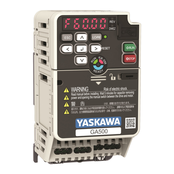
Industrial AC Microdrive, 240 V/480 V Single/Three-Phase Input: 1/6 / 1/2 to 5/30/40 HP
Brand:
YASKAWA
| Category:
DC Drives
| Size: 7.94 MB
Table of Contents
Table of Contents
3
1 General Information
7
2 Section Safety
7
Explanation of Signal Words
7
General Safety Instructions
7
Warranty Information
9
Exclusion of Liability
9
3 Drive Specifications
9
4 Moving the Drive
13
5 Receiving
13
How to Read the Catalog Code
14
Rated Output Current
15
6 Overview of Keypad Components and Functions
18
Keypad Mode and Menu Displays
21
7 Mechanical Installation
22
Drive Exterior and Mounting Dimensions
22
IP20/UL Open Type
22
Installation Position and Clearances
28
Removing/Reattaching Covers
30
Remove the
30
Reattach the
31
8 Electrical Installation
32
Standard Connection Diagram
33
Main Circuit Terminal Block Wiring Procedure
35
Wire to the Main Circuit Terminal Block
36
Main Circuit Terminal Functions
38
Wire Selection
39
Single-Phase 200 V Class
40
Three-Phase 200 V Class
43
Three-Phase 400 V Class
47
Motor and Main Circuit Connections
51
Control Circuit Terminal Block Functions
52
Input Terminals
53
Output Terminals
55
External Power Supply Input Terminals
56
Serial Communication Terminals
56
Control Circuit Terminal Configuration
56
Control Circuit Wire Gauges and Tightening Torques
57
Wiring the Control Circuit Terminal
58
Switches and Jumpers on the Terminal Board
61
Control I/O Connections
62
Set Sinking Mode/Sourcing Mode
62
Pulse Train Output
63
Set the Input Signal for the MFAI Terminal A2
64
Set the Output Signal for the MFAO Terminal am
65
Switch on Termination Resistor for Memobus/Modbus Communications
66
9 Auto-Tuning
67
Auto-Tuning for Induction Motors
67
Auto-Tuning for PM Motors
69
Auto-Tuning in EZ Open Loop Vector Control Method
72
ASR and Inertia Tuning
73
Precautions before Auto-Tuning
74
Prepare for Basic Auto-Tuning
74
Precautions before Rotational Auto-Tuning
75
Precautions before Stationary Auto-Tuning
76
Automatically Set E2-02 [Motor Rated Slip] and E2-03
76
Current]
76
Stator Resistance Auto-Tuning
76
Precautions before Using Deceleration Rate Tuning and KEB Tuning
76
10 Drive Start-Up
77
Set up the Drive with General-Purpose Setup Mode
77
Set and View Necessary Parameters
78
Automatic Parameter Settings Optimized for Specific Applications
79
Presets)
79
11 Maintenance
80
12 Drive Control, Duty Modes, and Programming
80
Control Method Selection
80
Drive Duty Modes
81
Auto-Tuning for Induction Motors
81
Drive Parameters
83
13 Troubleshooting
88
Fault Reset Procedure with the Keypad
88
Fault
89
Minor Faults/Alarms
108
Parameter Setting Errors
119
Auto-Tuning Errors
126
Backup Function Operating Mode Display and Errors
131
14 European Standards
133
EU Declaration of Conformity
134
CE Low Voltage Directive Compliance
134
Area of Use
134
Guarding against Debris
134
Wiring Diagram
134
Main Circuit Wire Gauges and Tightening Torques
136
Connect a Fuse to the Input Side (Primary Side)
148
CE Standards Compliance for DC Power Supply Input
150
EMC Directive
151
Install a Drive to Conform to the EMC Directive
151
Installing the External EMC Noise Filter
157
DC Link Chokes
161
15 UL Standards
162
Area of Use
162
Wire the Main Circuit Terminal Block
162
Notes on Wiring the Main Circuit Terminal Block
162
Main Circuit Wire Gauges and Tightening Torques
162
Factory-Recommended Branch Circuit Protection
175
Low Voltage Wiring for Control Circuit Terminals
178
Drive Motor Overload and Overheat Protection
178
E2-01: Motor Rated Current (FLA)
179
E5-03: Motor Rated Current (FLA)
179
E9-06: Motor Rated Current (FLA)
179
L1-01: Motor Overload (Ol1) Protection
180
L1-02: Motor Overload Protection Time
183
L1-03: Motor Thermistor Oh Alarm Select
184
L1-04: Motor Thermistor Oh Fault Select
184
16 China Rohs Compliance
185
Information on Hazardous Substances in this Product
185
17 对应中国Rohs指令
186
本产品中含有有害物质的信息
186
18 Safe Disable Input
187
Safe Disable Specifications
187
Notes
188
Using the Safe Disable Function
189
Safe Disable Circuit
189
Connect Safe Disable Input Contacts to Multiple Drives
190
Enabling and Disabling the Drive Output ("Safe Torque Off")
193
Safe Disable Monitor Output Function and Keypad Display
194
Validating the Safe Disable Function
195
19 Disposal
195
Disposal Instructions
195
WEEE Directive
195
Advertisement
Related Products
YASKAWA GA50U4004ABA
YASKAWA GA70C4296BBA
YASKAWA GA80U4605ABM
YASKAWA GA80U4302ABM
YASKAWA GA80U4208ABM
YASKAWA GA80U4168ABM
YASKAWA GA80U4250ABM
YASKAWA GA80U4004ABM
YASKAWA GA80U2008ABM
YASKAWA GA80U2006ABM
YASKAWA Categories
Controller
DC Drives
Servo Drives
Robotics
Control Unit
More YASKAWA Manuals
Login
Sign In
OR
Sign in with Facebook
Sign in with Google
Upload manual
Upload from disk
Upload from URL