
Related Manuals for WIKA FSD-3


Summary of Contents for WIKA FSD-3
- Page 1 Operating instructions Betriebsanleitung Mode d'emploi Flow switch, model FSD-3 Strömungsschalter, Typ FSD-3 Capteur de débit, type FSD-3 Flow switch, model FSD-3...
- Page 2 Betriebsanleitung Typ FSD-3 Seite 39 - 74 Mode d‘emploi type FSD-3 Page 75 - 110 © 09/2016 WIKA Alexander Wiegand SE & Co. KG All rights reserved. / Alle Rechte vorbehalten. ® WIKA is a registered trademark in various countries. ®...
-
Page 3: Table Of Contents
6. Faults 7. Maintenance and cleaning 8. Dismounting, return and disposal 9. Specifications 10. Accessories and spare parts 11. Appendix 1: EU declaration of conformity Declarations of conformity can be found online at www.wika.com WIKA operating instructions flow switch, model FSD-3... -
Page 4: General Information
■ Subject to technical modifications. ■ Further information: ■ - Internet address: www.wika.de / www.wika.com - Relevant data sheet: FL 80.01 - Application consultant: Tel.: +49 9372 132-8976 Fax: +49 9372 132-8008976 support-tronic@wika.de WIKA operating instructions flow switch, model FSD-3... -
Page 5: Design And Function
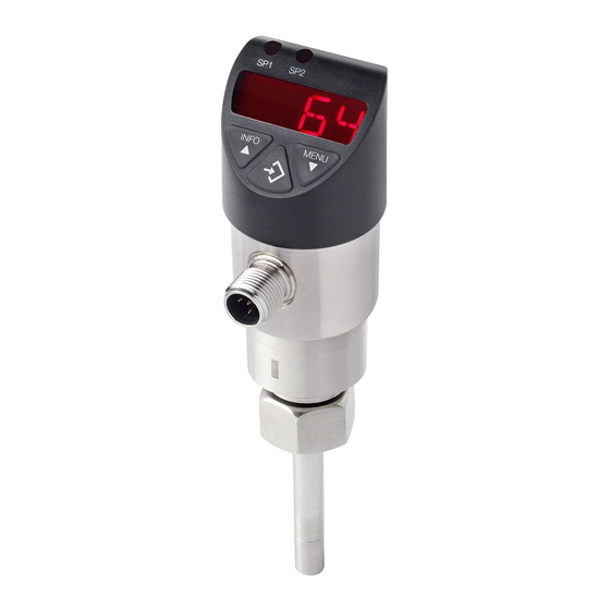
2. Design and function 2. Design and function 2.1 Overview Display and control panel Electrical connection Installation mark Process connection, spanner flats Probe WIKA operating instructions flow switch, model FSD-3... - Page 6 Analogue signal flow ■ Analogue signal temperature ■ 2.3 Scope of delivery Flow switch ■ Operating instructions ■ Accessories process connection (optional) ■ Further certificates (optional) ■ Cross-check scope of delivery with delivery note. WIKA operating instructions flow switch, model FSD-3...
-
Page 7: Safety
Ambient temperature between -20 ... +80 °C. ■ Medium temperature between -20 ... +85 °C. ■ Relative humidity between 45 ... 75 % r. h. ■ Use for commercial purposes in industrial environment. ■ WIKA operating instructions flow switch, model FSD-3... - Page 8 Special operating conditions require further appropriate knowledge, e.g. of aggressive media. WIKA operating instructions flow switch, model FSD-3...
- Page 9 P# Product no. Coded date of manufacture Measuring range (temperature) Max. pressure limitation Measuring range (flow) Before mounting and commissioning the instrument, ensure you read the operating instructions! DC voltage WIKA operating instructions flow switch, model FSD-3...
-
Page 10: Transport, Packaging And Storage
Direct sunlight or proximity to hot objects ■ Mechanical vibration, mechanical shock (putting it down hard) ■ Soot, vapour, dust and corrosive gases ■ Humid or wet environment ■ Hazardous environments, flammable atmospheres ■ WIKA operating instructions flow switch, model FSD-3... -
Page 11: Commissioning, Operation
Position the probe tip in the area of maximum flow rate ■ (pipe centre). The minimum immersion depth of the probe is L ≥16 mm. ■ The probe tip must not touch the opposite wall. ■ WIKA operating instructions flow switch, model FSD-3... - Page 12 Only if the pipeline is completely filled deposits. with medium. Risers and vertical pipes Mounting the flow switch in downpipes open towards the bottom is forbidden. This use does not comply with the intended use. WIKA operating instructions flow switch, model FSD-3...
- Page 13 5. Commissioning, operation 5.1.3 Probe alignment During mechanical assembly of the FSD-3, make sure that the installation mark points in the opposite direction of the flow direction of the medium. Installation mark 5.1.4 Sealing For sealing the process connections with parallel threads, use flat gaskets, lens-type sealing rings or WIKA profile sealings at the sealing face.
- Page 14 The flow switch must be shielded and grounded in accordance with the grounding concept of the plant. The instrument must be grounded via the process connection. Connecting the instrument 1. Assemble the mating connector. → see pin assignment Establish the plug connection. WIKA operating instructions flow switch, model FSD-3...
- Page 15 5. Commissioning, operation Pin assignment Circular connector M12 x 1 (4-pin) Legend: Positive power supply terminal Negative power supply terminal Switching output 1 Switching output 2 Analogue output WIKA operating instructions flow switch, model FSD-3...
- Page 16 Keep the “MENU” key pressed for approx. 5 seconds. If the password is set to ≠ 0000, a password will be requested first. If authentication is successful, then it enters the programming mode, otherwise it reverts to display mode. Returning to the display mode Simultaneous pressing of both keys. WIKA operating instructions flow switch, model FSD-3...
- Page 17 ▶ Long press Parameter value down (fast) Menu up Parameter value up (fast) Display mode ▶ Short press Display of unit Programming mode ▶ Short press Selection of menu item Confirmation of input WIKA operating instructions flow switch, model FSD-3...
- Page 18 SP2/FH2 = function switch point 2, RP2/FL2 = function reset point 2 DISR Rotate display by 180° Password input, 0000 = no password; password input digit by digit Input of a 16-figure alphanumeric measuring point number WIKA operating instructions flow switch, model FSD-3...
- Page 19 Flow, Temp, SP1, RP1, SP2, RP2, Off ▲ ▼ DISR Yes / No Rotate display by 180° ▲ ▼ Value Password ▲ ▼ Value TAG name (16 ASCI characters) ▲ ▼ ▼ ▼ ▼ ▼ Display mode WIKA operating instructions flow switch, model FSD-3...
- Page 20 With the flow rate falling again, the output will not switch back before the reset point (RP) is reached. Contact normally open (HNO): Inactive ■ Contact normally closed (HNC): Active ■ Fig.: Hysteresis function WIKA operating instructions flow switch, model FSD-3...
- Page 21 (RP) and stays at or below the reset point (RP) for at least the pre-set delay time (DR). Fig.: Delay times If the switching event is no longer present after the delay time, the switching output does not change. WIKA operating instructions flow switch, model FSD-3...
-
Page 22: Faults
For these media, in addition to all standard regulations, the appropriate existing codes or regulations must also be followed. ▶ Wear the requisite protective equipment. For contact details see chapter 1 “General information” or the back page of the operating instructions. WIKA operating instructions flow switch, model FSD-3... - Page 23 Wiring error Observe the pin assignment Wrong output signal Process temperature out of measuring Check temperature range range; sensor drift caused by overtemper- ature Probe break/short circuit Send the instrument to the manufacturer WIKA operating instructions flow switch, model FSD-3...
- Page 24 Deposit on the probe Remove deposit Signal span too small Power supply too high/low Rectify the power supply Signal span drops Moisture has entered Fit the cable correctly WIKA operating instructions flow switch, model FSD-3...
-
Page 25: Maintenance And Cleaning
Do not use any abrasive cloths or sponges. Suitable cleaning agents Water ■ Conventional dishwashing detergent ■ Cleaning the instrument 1. Disconnect the flow switch from the mains. 2. Wipe the instrument surface using a soft, damp cloth. WIKA operating instructions flow switch, model FSD-3... -
Page 26: Dismounting, Return And Disposal
Unscrew the flow switch with a spanner using the spanner flats. 8.2 Return Strictly observe the following when shipping the instrument: All instruments delivered to WIKA must be free from any kind of hazardous substances (acids, bases, solutions, etc.) and must therefore be cleaned before being returned. WARNING! - Page 27 Information on returns can be found under the heading “Service” on our local website. 8.3 Disposal Incorrect disposal can put the environment at risk. Dispose of instrument components and packaging materials in an environmentally compatible way and in accordance with the country-specific waste disposal regulations. WIKA operating instructions flow switch, model FSD-3...
-
Page 28: Specifications
Flow (50 ... 100 %, 100 ... 50 %): 4 s Temperature t : 4 s Temperature t : 2 s Load Analogue signal 4 ... 20 mA: ≤ 0.5 kΩ Service life 100 million switching cycles WIKA operating instructions flow switch, model FSD-3... - Page 29 DC 24 V Mounting position Process connection M18 x 1.5 downwards Inner diameter of pipe 26 mm Upstream/Downstream pipe: 1 m / 0.5 m Marking towards the upstream side twist of ±5° Load 100 Ω WIKA operating instructions flow switch, model FSD-3...
- Page 30 Electrical connection Connection Circular connector M12 x 1 (4-pin) Short-circuit resistance S+ / SP1 / SP2 vs. U- Reverse polarity protection U+ vs. U- Insulation voltage DC 500 V Overvoltage protection DC 40 V WIKA operating instructions flow switch, model FSD-3...
- Page 31 EMC directive, EN 61326 emission (group 1, class B) and interference immunity (industrial application) RoHS conformity 2011/65/EU (European union) SJ/T 11364-2014 (China) For further specifications see WIKA data sheet FL 80.01 and the order documentation. WIKA operating instructions flow switch, model FSD-3...
- Page 32 9. Specifications Dimensions in mm (in) (1.50) (∅ 1.38) (1.06) (∅ 0.31) Weight: approx. 0.3 kg (10.58 oz) WIKA operating instructions flow switch, model FSD-3...
- Page 33 105 mm (4.13 in) 119 mm (4.69 in) Option 7 ANSI/ASME B1.20.1 ¼ NPT 16 mm (0.63 in) 22 mm (0.87 in) Option 8 ANSI/ASME B1.20.1 ½ NPT 30 mm (1.18 in) 38 mm (1.50 in) WIKA operating instructions flow switch, model FSD-3...
-
Page 34: Accessories And Spare Parts
(-4 ... +176 °F) (0.18 in) Angled version, cut to length, 4-pin, 10 m (32.8 ft) PUR cable, -20 ... +80 °C 4.5 mm 14086892 UL listed, IP67 (-4 ... +176 °F) (0.18 in) WIKA operating instructions flow switch, model FSD-3... - Page 35 From M18 x 1.5 to G ½ 32 ... 100 mm 36 mm 22 mm on request short (1.26 ... 3.93 in) (1.41 in) (0.86 in) Legend Maximum probe immersion depth Distance sealing face to probe tip WIKA operating instructions flow switch, model FSD-3...
- Page 36 10. Accessories and spare parts FSD-3 with adapter Legend Maximum probe immersion depth Distance sealing face to probe tip WIKA operating instructions flow switch, model FSD-3...
-
Page 37: Appendix 1: Eu Declaration Of Conformity
Appendix 1: EU declaration of conformity WIKA operating instructions flow switch, model FSD-3... - Page 38 WIKA operating instructions flow switch, model FSD-3...
- Page 39 4. Transport, Verpackung und Lagerung 5. Inbetriebnahme, Betrieb 6. Störungen 7. Wartung und Reinigung 8. Demontage, Rücksendung und Entsorgung 9. Technische Daten 10. Zubehör und Ersatzteile 11. Anlage 1: EU-Konformitätserklärung Konformitätserklärungen finden Sie online unter www.wika.de WIKA Betriebsanleitung Strömungsschalter, Typ FSD-3...
-
Page 40: Allgemeines
Es gelten die allgemeinen Geschäftsbedingungen in den Verkaufsunterlagen. ■ Technische Änderungen vorbehalten. ■ Weitere Informationen: ■ - Internet-Adresse: www.wika.de / www.wika.com - Zugehöriges Datenblatt: FL 80.01 - Anwendungsberater: Tel.: +49 9372 132-8976 Fax: +49 9372 132-8008976 support-tronic@wika.de WIKA Betriebsanleitung Strömungsschalter, Typ FSD-3... -
Page 41: Aufbau Und Funktion 41 De
2. Aufbau und Funktion 2. Aufbau und Funktion 2.1 Überblick Anzeige- und Bedienfeld Elektrischer Anschluss Einbaumarkierung Prozessanschluss, Schlüsselfläche Fühler WIKA Betriebsanleitung Strömungsschalter, Typ FSD-3... - Page 42 Schaltsignal für Grenzwerte Temperatur ■ Schaltsignal für Diagnosefunktion ■ Analogsignal Strömung ■ Analogsignal Temperatur ■ 2.3 Lieferumfang Strömungsschalter ■ Betriebsanleitung ■ Zubehör Prozessanschluss (optional) ■ Weitere Bescheinigungen und Zeugnisse (optional) ■ Lieferumfang mit dem Lieferschein abgleichen. WIKA Betriebsanleitung Strömungsschalter, Typ FSD-3...
-
Page 43: Sicherheit
Spannungsversorgung der Überspannungskategorie II. ■ Umgebungstemperatur zwischen -20 … +80 °C. ■ Messstofftemperatur zwischen -20 … +85 °C. ■ Relative Luftfeuchte zwischen 45 … 75 % r. F. ■ Einsatz für gewerbliche Zwecke in industrieller Umgebung. ■ WIKA Betriebsanleitung Strömungsschalter, Typ FSD-3... - Page 44 Mess- und Regelungstechnik und seiner Erfahrungen sowie Kenntnis der landesspezifischen Vorschriften, geltenden Normen und Richtlinien in der Lage, die beschriebenen Arbeiten auszuführen und mögliche Gefahren selbstständig zu erkennen. Spezielle Einsatzbedingungen verlangen weiteres entsprechendes Wissen, z. B. über aggressive Medien. WIKA Betriebsanleitung Strömungsschalter, Typ FSD-3...
- Page 45 S# Serien-Nr. Anschlussbelegung (inkl. technischer Daten) P# Erzeugnis-Nr. Kodiertes Herstelldatum Messbereich (Temperatur) Max. Druckbelastbarkeit Messbereich (Strömung) Vor Montage und Inbetriebnahme des Gerätes unbedingt die Betriebsanleitung lesen! Gleichspannung WIKA Betriebsanleitung Strömungsschalter, Typ FSD-3...
-
Page 46: Transport, Verpackung Und Lagerung
Feuchtigkeit: 45 ... 75 % relative Feuchte (keine Betauung) ■ Folgende Einflüsse vermeiden: Direktes Sonnenlicht oder Nähe zu heißen Gegenständen ■ Mechanische Vibration, mechanischer Schock (hartes Aufstellen) ■ Ruß, Dampf, Staub und korrosive Gase ■ Feuchte oder nasse Umgebung ■ Explosionsgefährdete Umgebung, entzündliche Atmosphären ■ WIKA Betriebsanleitung Strömungsschalter, Typ FSD-3... -
Page 47: Inbetriebnahme, Betrieb
■ Ausreichend Platz für eine sichere elektrische Installation. ■ Luft Angaben zu Einschraublöchern und Einschweißstutzen ■ siehe Technische Information IN 00.14 unter www.wika.de. Messstoff Zulässige Umgebungs- und Messstofftemperaturen bleiben ■ innerhalb der Leistungsgrenzen. Mögliche Einschränkungen des Umgebungstemperaturbereichs durch verwendeten Gegenstecker berücksichtigen. - Page 48 Nur wenn die Rohrleitung vollständig mit Ablagerungen ist. Messstoff gefüllt ist. Steigleitungen und senkrecht verlaufende Rohre Die Montage des Strömungsschalters an nach unten geöffnete Fallrohre ist unzulässig. Dieser Anwendungsfall entspricht nicht der bestim- mungsgemäßen Verwendung. WIKA Betriebsanleitung Strömungsschalter, Typ FSD-3...
- Page 49 5. Inbetriebnahme, Betrieb 5.1.3 Ausrichtung des Fühlers Bei der mechanischen Montage des FSD-3 ist darauf zu achten, dass die Einbaumarkierung entgegengesetzt der Strömungsrichtung des Mediums zeigt. Einbaumar- kierung 5.1.4 Abdichtung Zur Abdichtung der Prozessanschlüsse mit zylindri- schem Gewinde an der Dichtfläche sind Flachdichtun- gen, Dichtlinsen oder WIKA-Profildichtungen einzuset- zen.
- Page 50 Strömungsschalter ab dieser Höhe verwendet wird. Anforderung an Schirmung und Erdung Der Strömungsschalter muss entsprechend dem Erdungskonzept der Anlage geschirmt und geerdet werden. Das Gerät über den Prozessanschluss erden. Gerät anschließen 1. Gegenstecker konfektionieren. → siehe Anschlussbelegung Steckverbindung herstellen. WIKA Betriebsanleitung Strömungsschalter, Typ FSD-3...
- Page 51 5. Inbetriebnahme, Betrieb Anschlussbelegung Rundstecker M12 x 1 (4-polig) Legende: Positiver Versorgungsanschluss Negativer Versorgungsanschluss Schaltausgang 1 Schaltausgang 2 Analogausgang WIKA Betriebsanleitung Strömungsschalter, Typ FSD-3...
- Page 52 Taste „MENU“ etwa 5 Sekunden lang betätigen. Falls Passwort ≠ 0000 gesetzt ist erfolgt erst eine Passwortabfrage. Bei erfolgreicher Bestätigung erfolgt der Zugang zum Programmiermodus, ansonsten erfolgt Rücksprung in Displaymodus. Rücksprung in den Displaymodus Gleichzeitige Betätigung beider Tasten. WIKA Betriebsanleitung Strömungsschalter, Typ FSD-3...
- Page 53 Parameterwert aufwärts (schrittweise) ▶ Lange Betätigung Menü abwärts ▶ Lange Betätigung Parameterwert abwärts (schnell) Menü aufwärts Parameterwert aufwärts (schnell) Displaymodus ▶ Kurze Betätigung Anzeige der Einheit Programmiermodus ▶ Kurze Betätigung Auswahl Menüpunkt Bestätigung der Eingabe WIKA Betriebsanleitung Strömungsschalter, Typ FSD-3...
- Page 54 SP1/FH1 = Funktion Schaltpunkt 1, RP1/FL1 = Funktion Rückschaltpunkt 1, SP2/FH2 = Funktion Schaltpunkt 2, RP2/FL2 = Funktion Rückschaltpunkt 2 DISR Display-Anzeige 180° drehen Passworteingabe, 0000 = kein Passwort; Passworteingabe Digit by Digit Eingabe einer 16-stelligen alphanumerischen Messstellennummer WIKA Betriebsanleitung Strömungsschalter, Typ FSD-3...
- Page 55 PARA Flow, Temp, SP1, RP1, SP2, RP2, Off ▲ ▼ DISR Yes / No Display-Anzeige um 180° drehen ▲ ▼ Wert Passwort ▲ ▼ Wert TAG-Name (16 ASCI-Zeichen) ▲ ▼ ▼ ▼ ▼ ▼ Displaymodus WIKA Betriebsanleitung Strömungsschalter, Typ FSD-3...
- Page 56 Schließerkontakt (HNO): aktiv ■ Öffnerkontakt (HNC): inaktiv ■ Fällt die Strömungsgeschwindigkeit wieder ab, schaltet der Ausgang erst wieder zurück, wenn der Rückschaltpunkt (RP) erreicht ist. Schließerkontakt (HNO): inaktiv ■ Öffnerkontakt (HNC): aktiv ■ Abb.: Hysteresefunktion WIKA Betriebsanleitung Strömungsschalter, Typ FSD-3...
- Page 57 Rückschaltpunkt (RP) abgefallen ist und mindestens die eingestellte Verzögerungszeit (DR) auf bzw. unter dem Rückschaltpunkt (RP) bleibt. Abb.: Verzögerungszeiten Besteht das Schaltereignis nach Ablauf der Verzögerungszeit nicht mehr, ändert sich der Schaltausgang nicht. WIKA Betriebsanleitung Strömungsschalter, Typ FSD-3...
-
Page 58: Störungen
Am Gerät können im Fehlerfall aggressive Messstoffe mit extremer Temperatur und unter hohem Druck oder Vakuum anliegen. ▶ Bei diesen Messstoffen müssen über die gesamten allgemeinen Regeln hinaus die einschlägigen Vorschriften beachtet werden. ▶ Notwendige Schutzausrüstung tragen. Kontaktdaten siehe Kapitel 1 „Allgemeines“ oder Rückseite der Betriebsanleitung. WIKA Betriebsanleitung Strömungsschalter, Typ FSD-3... - Page 59 Kein Ausgangssignal Keine/falsche Hilfsenergie Hilfsenergie korrigieren Kein/falsches Ausgangssignal Verdrahtungsfehler Anschlussbelegung beachten Falsches Ausgangssignal Prozesstemperatur außerhalb des Messbe- Temperaturbereich überprüfen reiches; Sensordrift durch Übertemperatur Sensorbruch/-kurzschluss Gerät zum Hersteller senden Falsches Ausgangssignal Sensordrift durch chemischen Angriff Medienverträglichkeit prüfen WIKA Betriebsanleitung Strömungsschalter, Typ FSD-3...
- Page 60 Ansprechzeit Einbautiefe und zu hohe Wärmeableitung Sensors in das Medium bringen Ablagerung auf dem Sensor Ablagerung entfernen Signalspanne zu klein Hilfsenergie zu hoch/niedrig Hilfsenergie korrigieren Signalspanne fällt ab Feuchtigkeit eingetreten Kabel korrekt montieren WIKA Betriebsanleitung Strömungsschalter, Typ FSD-3...
-
Page 61: Wartung Und Reinigung
Keine aggressiven Reinigungsmittel verwenden. ▶ Keine harten oder spitzen Gegenstände verwenden. ▶ Keine scheuernden Tücher oder Schwämme verwenden. Geeignete Reinigungsmittel Wasser ■ Handelsüblicher Geschirrreiniger ■ Gerät reinigen 1. Strömungsschalter stromlos schalten. 2. Geräteoberfläche mit weichem, feuchten Tuch abwischen. WIKA Betriebsanleitung Strömungsschalter, Typ FSD-3... -
Page 62: Demontage, Rücksendung Und Entsorgung
Elektrische Verbindung trennen. Strömungsschalter mit Schraubenschlüssel über Schlüsselfläche ausschrauben. 8.2 Rücksendung Beim Versand des Gerätes unbedingt beachten: Alle an WIKA gelieferten Geräte müssen frei von Gefahrstoffen (Säuren, Laugen, Lösungen, etc.) sein und sind daher vor der Rücksendung zu reinigen. WARNUNG! Körperverletzungen, Sach- und Umweltschäden durch Messstoffreste Messstoffreste im ausgebauten Gerät können zur Gefährdung von Personen, Umwelt und Einrichtung... - Page 63 Hinweise zur Rücksendung befinden sich in der Rubrik „Service“ auf unserer lokalen Internetseite. 8.3 Entsorgung Durch falsche Entsorgung können Gefahren für die Umwelt entstehen. Gerätekomponenten und Verpackungsmaterialien entsprechend den landesspezifischen Abfallbehandlungs- und Entsorgungsvorschriften umweltgerecht entsorgen. WIKA Betriebsanleitung Strömungsschalter, Typ FSD-3...
-
Page 64: Technische Daten
Strömung (0 ... 100 %, 100 ... 0 %): 6 s Strömung (50 ... 100 %, 100 ... 50 %): 4 s Temperatur t : 4 s Temperatur t : 2 s Bürde Analogsignal 4 ... 20 mA: ≤ 0,5 kΩ Lebensdauer 100 Millionen Schaltwechsel WIKA Betriebsanleitung Strömungsschalter, Typ FSD-3... - Page 65 45 ... 75 % r. F. Messstoff Wasser Hilfsenergie DC 24 V Einbaulage Prozessanschluss M18 x 1,5 nach unten Rohrinnendurchmesser 26 mm Ein-/Auslaufstrecke: 1 m / 0,5 m Markierung zur Anströmseite ±5° Verdrehung Bürde 100 Ω WIKA Betriebsanleitung Strömungsschalter, Typ FSD-3...
- Page 66 Gehäuse: CrNi-Stahl 304 Tastatur: TPE-E Digitalanzeige: PC Anzeigekopf: PC+ABS-Blend Elektrischer Anschluss Anschluss Rundstecker M12 x 1 (4-polig) Kurzschlussfestigkeit S+ / SP1 / SP2 gegen U- Verpolungsschutz U+ gegen U- Isolationsspannung DC 500 V Überspannungsschutz DC 40 V WIKA Betriebsanleitung Strömungsschalter, Typ FSD-3...
- Page 67 Technische Daten Zulassungen, Herstellerinformationen und Bescheinigungen EU-Konformität EMV-Richtlinie, EN 61326 Emission (Gruppe 1, Klasse B) und Störfestigkeit (industrieller Bereich) RoHS-Konformität 2011/65/EU (Europäische Union) SJ/T 11364-2014 (China) Weitere technische Daten siehe WIKA-Datenblatt FL 80.01 und Bestellunterlagen. WIKA Betriebsanleitung Strömungsschalter, Typ FSD-3...
- Page 68 9. Technische Daten Abmessungen in mm (in) (1,50) (∅ 1,38) (1,06) (∅ 0,31) Gewicht: ca. 0,3 kg (10,58 oz) WIKA Betriebsanleitung Strömungsschalter, Typ FSD-3...
- Page 69 105 mm (4,13 in) 119 mm (4,69 in) Option 7 ANSI/ASME B1.20.1 ¼ NPT 16 mm (0,63 in) 22 mm (0,87 in) Option 8 ANSI/ASME B1.20.1 ½ NPT 30 mm (1,18 in) 38 mm (1,50 in) WIKA Betriebsanleitung Strömungsschalter, Typ FSD-3...
-
Page 70: Zubehör Und Ersatzteile
PUR-Kabel, UL listed, IP 67 (-4 ... +176 °F) (0,18 in) Abgewinkelte Ausführung, offenes Ende, 4-polig, 10 m (32,8 -20 ... +80 °C 4,5 mm 14086892 ft) PUR-Kabel, UL listed, IP 67 (-4 ... +176 °F) (0,18 in) WIKA Betriebsanleitung Strömungsschalter, Typ FSD-3... - Page 71 (0,67 in) Von M18 x 1,5 auf G ½ kurz 32 ... 100 mm 36 mm 22 mm auf Anfrage (1,26 ... 3,93 in) (1,41 in) (0,86 in) Legende Maximale Fühlereintauchtiefe Abstand Dichtfläche bis Fühlerspitze WIKA Betriebsanleitung Strömungsschalter, Typ FSD-3...
- Page 72 10. Zubehör und Ersatzteile FSD-3 mit Adapter Legende Maximale Fühlereintauchtiefe Abstand Dichtfläche bis Fühlerspitze WIKA Betriebsanleitung Strömungsschalter, Typ FSD-3...
-
Page 73: Anlage 1: Eu-Konformitätserklärung
Anlage 1: EU-Konformitätserklärung WIKA Betriebsanleitung Strömungsschalter, Typ FSD-3... - Page 74 WIKA Betriebsanleitung Strömungsschalter, Typ FSD-3...
- Page 75 8. Démontage, retour et mise au rebut 9. Spécifications 10. Accessoires et pièces de rechange 11. Annexe 1 : Déclaration de conformité UE Déclarations de conformité disponibles en ligne sur www.wika.com WIKA mode d'emploi pour le capteur de débit, type FSD-3...
-
Page 76: Généralités
- Consulter notre site Internet : www.wika.fr - Fiche technique correspondante : FL 80.01 - Conseiller applications : Tel.: 0 820 951010 (0,15 €/min) Fax: 0 891 035891 (0,35 €/min) info@wika.fr WIKA mode d'emploi pour le capteur de débit, type FSD-3... -
Page 77: Conception Et Fonction 77 Fr
2. Conception et fonction 2.1 Vue générale Affichage et panneau de contrôle Raccordement électrique Marque d'installation Raccord process, surfaces de clé Capteur WIKA mode d'emploi pour le capteur de débit, type FSD-3... - Page 78 Capteur de débit ■ Mode d'emploi ■ Accessoires pour raccord process (en option) ■ Autres certificats (en option) ■ Comparer le détail de la livraison avec le bordereau de livraison. WIKA mode d'emploi pour le capteur de débit, type FSD-3...
-
Page 79: Sécurité
Température ambiante entre -20 ... +80 °C. ■ Température fluide entre -20 ... +85 °C. ■ Humidité relative entre 45 ... 75 % h.r. ■ Utilisation dans des buts commerciaux dans un environnement industriel. ■ WIKA mode d'emploi pour le capteur de débit, type FSD-3... - Page 80 Les conditions d'utilisation spéciales exigent également une connaissance adéquate, par ex. des liquides agressifs. WIKA mode d'emploi pour le capteur de débit, type FSD-3...
- Page 81 Etendue de mesure (température) Limitation maximale de pression Etendue de mesure (débit) Lire impérativement le mode d'emploi avant le montage et la mise en service de l'instrument ! Tension DC WIKA mode d'emploi pour le capteur de débit, type FSD-3...
-
Page 82: Transport, Emballage Et Stockage
Lumière solaire directe ou proximité d'objets chauds ■ Vibrations mécaniques, chocs mécaniques (mouvements brusques en le posant) ■ Suie, vapeur, poussière et gaz corrosifs ■ Environnement humide et mouillé ■ Environnements dangereux, atmosphères inflammables ■ WIKA mode d'emploi pour le capteur de débit, type FSD-3... -
Page 83: Mise En Service, Utilisation
Positionner l'extrémité du capteur dans la zone où règne le débit maximum (centre du tuyau). ■ La profondeur d'immersion minimale du capteur est L ≥16 mm. ■ L'extrémité du capteur ne doit pas toucher la paroi opposée. ■ WIKA mode d'emploi pour le capteur de débit, type FSD-3... - Page 84 Tuyaux ascendants et tuyauteries verticales Il est interdit d'installer le capteur de débit dans des tuyauteries qui sont ouvertes vers le bas. Une telle utilisation ne correspond pas à l'utilisation prévue. WIKA mode d'emploi pour le capteur de débit, type FSD-3...
- Page 85 L > 3 ... 5 x D WIKA mode d'emploi pour le capteur de débit, type FSD-3...
- Page 86 Le capteur de débit doit être isolé et mis à la terre en conformité avec le concept de mise à la terre de l'installation. L'instrument doit être mis à la terre par le raccord process. Connexion de l'instrument 1. Assembler le contre-connecteur., → voir la configuration du raccordement Etablir la connexion. WIKA mode d'emploi pour le capteur de débit, type FSD-3...
- Page 87 5. Mise en service, utilisation Configuration du raccordement Connecteur circulaire M12 x 1 (4 plots) Légende : Alimentation positive Alimentation négative Sortie de commutation 1 Sortie de commutation 2 Sortie analogique WIKA mode d'emploi pour le capteur de débit, type FSD-3...
- Page 88 Si l'authentification est couronnée de succès, alors elle entre en mode programmation, sinon elle revient en mode affichage. Retour au mode d'affichage On presse les deux touches simultanément. WIKA mode d'emploi pour le capteur de débit, type FSD-3...
- Page 89 Valeur de paramètre vers le bas (rapidement) Menu haut Valeur de paramètre haut (rapidement) Mode d'affichage ▶ Pression courte Affichage de l'unité Mode de programmation ▶ Pression courte Sélection de l'élément de menu Confirmation de l'entrée WIKA mode d'emploi pour le capteur de débit, type FSD-3...
- Page 90 Entrée du mot de passe, 0000 = aucun mot de passe; entrée de mot de passe chiffre par chiffre Entrée d'un numéro de point de mesure alphanumérique à 16 chiffres WIKA mode d'emploi pour le capteur de débit, type FSD-3...
- Page 91 Oui / Non Rotation de l'affichage de 180° ▲ ▼ Valeur Mot de passe ▲ ▼ Valeur Nom de TAG (16 caractères ASCI) ▲ ▼ ▼ ▼ ▼ ▼ Mode d'affichage WIKA mode d'emploi pour le capteur de débit, type FSD-3...
- Page 92 Si le taux de débit retombe, la sortie ne recommutera pas avant que le point de retour (RP) ait été atteint. Contact normalement ouvert (HNO) : inactivé ■ Contact normalement fermé (HNC) : activé ■ Fig. : fonction d'hystérésis WIKA mode d'emploi pour le capteur de débit, type FSD-3...
- Page 93 été réglée (DR). Fig. : temps de temporisation Si la situation de commutation n'est plus présente après écoulement de la durée de temporisation, la sortie de commutation ne change pas. WIKA mode d'emploi pour le capteur de débit, type FSD-3...
-
Page 94: Dysfonctionnements
En cas de panne, vérifier d'abord si le capteur de débit est installé correctement, au niveau mécanique et électrique. Si la réclamation n'est pas justifiée, nous vous facturerons les frais de traitement de la réclamation. WIKA mode d'emploi pour le capteur de débit, type FSD-3... - Page 95 élevée Rupture de capteur/Court-circuit Envoyer l'instrument au fabricant Mauvais signal de sortie Dérive du capteur causée par une attaque Vérifier la compatibilité avec des produits chimique WIKA mode d'emploi pour le capteur de débit, type FSD-3...
- Page 96 Dépôt sur le capteur Enlever le dépôt Echelle de signaux trop petite Alimentation trop élevée / basse Corriger l'alimentation Plage de signaux tombe L'humidité a pénétrée Monter le câble correctement WIKA mode d'emploi pour le capteur de débit, type FSD-3...
-
Page 97: Entretien Et Nettoyage
Agents de nettoyage appropriés ■ Liquide vaisselle conventionnel ■ Nettoyage de l'instrument 1. Débrancher le capteur de débit du secteur. 2. Essuyer la surface de l'instrument avec un chiffon doux et humide. WIKA mode d'emploi pour le capteur de débit, type FSD-3... -
Page 98: Démontage, Retour Et Mise Au Rebut
Dévisser le capteur de débit avec une clé en utilisant les parties plates de la clé. 8.2 Retour En cas d'envoi de l'instrument, il faut respecter impérativement ceci : Tous les instruments livrés à WIKA doivent être exempts de substances dangereuses (acides, bases, solutions, etc.) et doivent donc être nettoyés avant d'être retournés. AVERTISSEMENT ! Blessures physiques et dommages aux équipements et à... - Page 99 Une mise au rebut inadéquate peut entraîner des dangers pour l'environnement. Eliminer les composants des instruments et les matériaux d'emballage conformément aux prescriptions nationales pour le traitement et l'élimination des déchets et aux lois de protection de l'environnement en vigueur. WIKA mode d'emploi pour le capteur de débit, type FSD-3...
-
Page 100: Spécifications
Débit (50 ... 100 %, 100 ... 50 %) : 4 s Température t : 4 s Température t : 2 s Charge ≤ 0,5 kΩ Durée de vie 100 millions de cycles de commutation WIKA mode d'emploi pour le capteur de débit, type FSD-3... - Page 101 Raccord process M18 x 1,5 vers le bas Diamètre intérieur de la tuyauterie 26 mm Tuyau en amont/en aval : 1 m / 0,5 m Marquage vers la torsion côté amont de ±5° Charge 100 Ω WIKA mode d'emploi pour le capteur de débit, type FSD-3...
- Page 102 Connecteur circulaire M12 x 1 (4 plots) Résistance court-circuit S+ / SP1 / SP2 vs. U- Protection contre l'inversion de U+ vs. U- polarité Tension d'isolement 500 VDC Protection contre la surtension 40 VDC WIKA mode d'emploi pour le capteur de débit, type FSD-3...
- Page 103 Directive CEM, EN 61326 émission (groupe 1, classe B) et immunité d'interférence (application industrielle) Conformité RoHS 2011/65/UE (Union européenne) SJ/T 11364-2014 (Chine) Pour de plus amples spécifications, voir la fiche technique WIKA FL 80.01 et la documentation de commande. WIKA mode d'emploi pour le capteur de débit, type FSD-3...
- Page 104 9. Spécifications Dimensions en mm (pouces) (1,50) (∅ 1,38) (1,06) (∅ 0,31) Poids: environ 0,3 kg (10,58 oz) WIKA mode d'emploi pour le capteur de débit, type FSD-3...
- Page 105 119 mm (4,69 in) Option 7 ANSI/ASME B1.20.1 ¼ NPT 16 mm (0,63 in) 22 mm (0,87 in) Option 8 ANSI/ASME B1.20.1 ½ NPT 30 mm (1,18 in) 38 mm (1,50 in) WIKA mode d'emploi pour le capteur de débit, type FSD-3...
-
Page 106: Accessoires Et Pièces De Rechange
Version coudée, extrémité ouverte, 4 plots, câble PUR de 10 -20 ... +80 °C 4,5 mm 14086892 m (32,8 ft), homologué UL, IP 67 (-4 ... 176 °F) (0,18 pouces) WIKA mode d'emploi pour le capteur de débit, type FSD-3... - Page 107 32 ... 100 mm 36 mm 22 mm sur demande (1,26 ... 3,93 in) (1,41 (0,86 pouces) pouces) Légende Profondeur d'immersion maximale du capteur Distance entre la surface d'étanchéité et l'extrémité du capteur WIKA mode d'emploi pour le capteur de débit, type FSD-3...
- Page 108 10. Accessoires et pièces de rechange FSD-3 avec adaptateur Légende Profondeur d'immersion maximale du capteur Distance entre la surface d'étanchéité et l'extrémité du capteur WIKA mode d'emploi pour le capteur de débit, type FSD-3...
-
Page 109: Annexe 1 : Déclaration De Conformité Ue
Annexe 1 : Déclaration de conformité UE WIKA mode d'emploi pour le capteur de débit, type FSD-3... - Page 110 WIKA mode d'emploi pour le capteur de débit, type FSD-3...
- Page 111 WIKA mode d'emploi pour le capteur de débit, type FSD-3...
- Page 112 WIKA Alexander Wiegand SE & Co. KG Alexander-Wiegand-Straße 30 63911 Klingenberg • Germany Tel. +49 9372 132-0 Fax +49 9372 132-406 info@wika.de www.wika.de...
Need help?
Do you have a question about the FSD-3 and is the answer not in the manual?
Questions and answers