Table of Contents
Advertisement
Available languages
Available languages
Quick Links
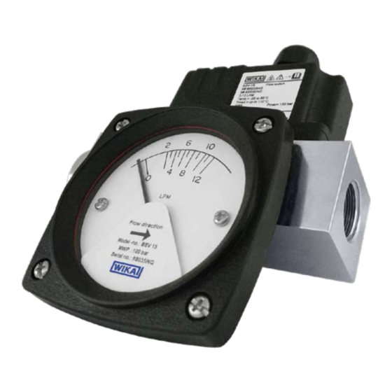
Flow switch, model FSM-BSV
Durchflussschalter, Typ FSM-BSV
Désignation produit, type FSM-BSV
Denominación de producto, modelo FSM-BSV
Flow switch, model FSM-BSV
Operating instructions
Betriebsanleitung
Mode d'emploi
Manual de instrucciones
Page
Seite
Page
Página
3 - 25
EN
22 - 49
DE
50 - 73
FR
74 - 97
ES
Advertisement
Chapters
Table of Contents

Related Manuals for WIKA FSM-BSV


Summary of Contents for WIKA FSM-BSV
- Page 1 Mode d'emploi Manual de instrucciones Flow switch, model FSM-BSV Page 3 - 25 Durchflussschalter, Typ FSM-BSV Seite 22 - 49 Désignation produit, type FSM-BSV Page 50 - 73 Denominación de producto, modelo FSM-BSV Página 74 - 97 Flow switch, model FSM-BSV...
-
Page 2: Table Of Contents
5. Commissioning, operation 6. Faults 7. Maintenance, cleaning 8. Dismounting, return and disposal 9. Specifications © 06/2023 WIKA Alexander Wiegand SE & Co. KG All rights reserved. WIKA is a registered trademark in various countries. ® WIKA operating instructions, model FSM-BVS... -
Page 3: General Information
Subject to technical modifications. ■ Factory calibrations/DAkkS calibrations are carried out in accordance with international standards. ■ Further information: ■ - Website: www.wika.de / www.wika.com - Relevant data sheet: FL 60.02 - Contact: Tel.: +49 9372 132-0 info@wika.com WIKA operating instructions, model FSM-BVS... -
Page 4: Short Overview
2.2 Description The model FSM-BSV is a piston flow switch integrating a BaFe magnet (barium ferrite), which works against a spring mechanism. The switch lever is mechanically coupled with the piston magnet. The switch is actuated as soon as the force generated by the flow is greater than the spring force. -
Page 5: Safety
3.2 Intended use The model FSM-BSV is a mechanical flow switch that is actuated through magnetic coupling between the switch lever and the piston magnet. The switch point can be specified by the customer on site. The instrument can switch electrical loads of up to AC 250 V, 3 A. - Page 6 The technical specifications contained in these operating instructions must be observed. It is assumed that the instrument is handled properly and within its technical specifications. Otherwise, the instrument must be taken out of service immediately and inspected by an authorised WIKA service engineer, see chapter “8. Dismounting, return and disposal”.
- Page 7 Before mounting and commissioning the instrument, ensure you read the operating instructions! Potentially dangerous situation caused by hot surfaces. Do not dispose of with household waste. Ensure a proper disposal in accordance with national regulations. WIKA operating instructions, model FSM-BVS...
-
Page 8: Transport, Packaging And Storage
Mechanical vibration, mechanical shock (putting it down hard) ■ Soot, vapour, dust and corrosive gases ■ Hazardous environments, flammable atmospheres ■ Store the instrument in its original packaging in a location that fulfils the conditions listed above. WIKA operating instructions, model FSM-BVS... -
Page 9: Commissioning, Operation
After unpacking the instrument, a visual inspection for damage must be carried out. ■ Unplug the thread protective caps from the process connection. ■ Check for the instrument specification in the data label to confirm requirements. ■ WIKA operating instructions, model FSM-BVS... - Page 10 5 x the pipe diameter both upstream and downstream. The straight upstream and downstream pipe should be free of bends, valves and other restrictions. The process connection is available in two versions: BSP female and NPT female. Select the mating pipe ■ connection accordingly. WIKA operating instructions, model FSM-BVS...
- Page 11 → Dimension ‘A’ must be at least 5 x the pipe diameter from the nearest angled valve or other restrictions. Wiring Before piston actuation After piston actuation The instrument is delivered with a 4-pin M12 x 1 connector. A 4-wire cable with 1 mm conductor cross-section is recommended. WIKA operating instructions, model FSM-BVS...
- Page 12 Switch off the load circuit before starting work and secure against unauthorised switching on. EMC problems affecting the switch contact frequently occur if many electronic devices are located within a small space. Ensure sufficient distance to magnetic fields (e.g. electric motors). WIKA operating instructions, model FSM-BVS...
- Page 13 (not shown). 1. Connect the model FSM-BSV flow switch, the flow reference and the flow generator to a common flow system. 2. With the flow generator and flow reference, slowly approach the required switch point flow.
- Page 14 Ensure that the flow is stabilised before reading the indicator. Read the value from the measuring scale. To achieve the highest accuracy of reading, read the pointer on the measuring scale at eye level. Without indicator, 2 x SPDT WIKA operating instructions, model FSM-BVS...
-
Page 15: Faults
Check the pin assignment and correct it if necessary point/reset point Electrical load unsuitable Maintain the permissible electrical loads Contact contaminated Replace instrument Short-circuit Moisture in the instrument Only use in ambient conditions for which the ingress protection is suitable WIKA operating instructions, model FSM-BVS... -
Page 16: Maintenance, Cleaning
For contact details, see chapter 1 “General information” or the back page of the operating instructions. 7.1 Maintenance The instrument model FSM-BSV is low-maintenance. The switch point setting must be checked after 3 months. Carry out switch point setting with matching test setup, see chapter 5.5 “Switch point setting”. -
Page 17: Dismounting, Return And Disposal
▶ Observe the information in the material safety data sheet for the corresponding medium. ▶ Wash or clean the dismounted instrument, in order to protect persons and the environment from exposure to residual media. WIKA operating instructions, model FSM-BVS... - Page 18 8.2 Return Strictly observe the following when shipping the instrument: All instruments delivered to WIKA must be free from any kind of hazardous substances (acids, bases, solutions, etc.) and must therefore be cleaned before being returned. When returning the instrument, use the original packaging or a suitable transport packaging.
-
Page 19: Specifications
9. Specifications Depending on the selected instrument version (e.g. seal), the specification may deviate from the specifications listed here. The specifications in the order documentation are definitive. For further specifications, see WIKA data sheet FL 60.02. Basic information Contact version Without ■... - Page 20 Setting range, decreasing or FL (flow limit) in LPM (litres per minute) increasing flow in LPM (litres per 1) 3) 4) minute) DN 8 0.3 ... 3 0.5 ... 5 1 ... 8 2 ... 12 WIKA operating instructions, model FSM-BVS...
- Page 21 7 ... 35 12 ... 40 0.3 ... 3 DN 20 0.5 ... 5 1 ... 8 2 ... 12 5 ... 25 7 ... 35 10 ... 40 25 ... 60 40 ... 85 WIKA operating instructions, model FSM-BVS...
- Page 22 40 ... 110 50 ... 150 DN 40 40 ... 110 50 ... 150 60 ... 230 DN 50 50 ... 150 75 ... 175 90 ... 220 DN 65 100 ... 200 180 ... 330 WIKA operating instructions, model FSM-BVS...
- Page 23 ¾ BSP, female thread ■ 1 BSP, female thread ■ 1 ¼ BSP, female thread ■ 1 ½ BSP, female thread ■ 2 BSP, female thread ■ 2 ½ BSP, female thread ■ 3 BSP, female thread ■ WIKA operating instructions, model FSM-BVS...
- Page 24 → Liquid media with the property of changing the volume during solidification can damage the measuring system (e.g. water if it falls below the freezing point). Ambient temperature range -20 ... +80 °C [-4 ... +176 °F] Storage temperature range -20 ... +80 °C [-4 ... +176 °F] WIKA operating instructions, model FSM-BVS...
- Page 25 30 V 125 V 250 V 0.4 A 0.2 A 0.4 A 0.2 A Approvals Logo Description Region EU declaration of conformity European Union Low Voltage Directive RoHS directive → For approvals and certificates, see website WIKA operating instructions, model FSM-BVS...
- Page 26 5. Inbetriebnahme, Betrieb 6. Störungen 7. Wartung, Reinigung 8. Demontage, Rücksendung und Entsorgung 9. Technische Daten © 06/2023 WIKA Alexander Wiegand SE & Co. KG Alle Rechte vorbehalten. WIKA ist eine geschützte Marke in verschiedenen Ländern. ® WIKA-Betriebsanleitung, Typ FSM-BVS...
-
Page 27: Allgemeines
Es gelten die allgemeinen Geschäftsbedingungen in den Verkaufsunterlagen. ■ Technische Änderungen vorbehalten. ■ Werkskalibrierungen/DAkkS-Kalibrierungen erfolgen nach internationalen Normen. ■ Weitere Informationen: ■ - Webseite: www.wika.de / www.wika.com - Zugehöriges Datenblatt: FL 60.02 - Kontakt: Tel.: +49 9372 132-0 info@wika.de WIKA-Betriebsanleitung, Typ FSM-BVS... -
Page 28: Kurzübersicht
2.2 Beschreibung Der Typ FSM-BSV ist ein Kolben-Durchflussschalter mit integriertem BaFe-Magnet (Bariumferrit), der gegen einen Federmechanismus arbeitet. Der Schalthebel ist mechanisch an den Kolbenmagneten gekoppelt. Der Schalter wird betätigt, sobald die Kraft des Durchflusses größer ist als die Federkraft. -
Page 29: Sicherheit
Betrieb hervor. 3.2 Bestimmungsgemäße Verwendung Der Typ FSM-BSV ist ein mechanischer Durchflussschalter, der über magnetische Kupplung zwischen Schalthebel und Kolbenmagnet betätigt wird. Der Schaltpunkt kann kundenspezifisch vor Ort eingestellt werden. Das Gerät kann elektrische Lasten von bis zu AC 250 V, 3 A schalten. - Page 30 Die technischen Spezifikationen in dieser Betriebsanleitung sind einzuhalten. Eine sachgemäße Handhabung und das Betreiben des Geräts innerhalb der technischen Spezifikationen wird vorausgesetzt. Andernfalls ist eine sofortige Stilllegung und Überprüfung durch einen autorisierten WIKA-Servicemitarbeiter erforderlich, siehe „8. Demontage, Rücksendung und Entsorgung“.
- Page 31 - max. Umgebungstemperatur Herstelldatum Durchflussbereich Vor Montage und Inbetriebnahme des Geräts unbedingt die Betriebsanleitung lesen! Möglicherweise gefährliche Situation durch heiße Oberflächen. Nicht mit dem Hausmüll entsorgen. Für eine geordnete Entsorgung nach nationalen Vorgaben sorgen. WIKA-Betriebsanleitung, Typ FSM-BVS...
-
Page 32: Transport, Verpackung Und Lagerung
Direktes Sonnenlicht oder Nähe zu heißen Gegenständen ■ Mechanische Vibration, mechanischer Schock (hartes Aufstellen) ■ Ruß, Dampf, Staub und korrosive Gase ■ Explosionsgefährdete Umgebung, entzündliche Atmosphären ■ Das Gerät in der Originalverpackung an einem Ort lagern, der die oben gelisteten Bedingungen erfüllt. WIKA-Betriebsanleitung, Typ FSM-BVS... -
Page 33: Inbetriebnahme, Betrieb
Vor Montage, Inbetriebnahme und Betrieb sicherstellen, dass das richtige Gerät hinsichtlich Ausführung und spezifischen Messbedingungen ausgewählt wurde. Nach Auspacken des Geräts, Sichtprüfung auf Beschädigungen durchführen. ■ Gewindeschutzkappen von Prozessanschluss abnehmen. ■ Gerätespezifikation in der Datenbeschriftung prüfen, um Anforderung zu bestätigen. ■ WIKA-Betriebsanleitung, Typ FSM-BVS... - Page 34 5 x Rohrdurchmesser sowohl stromaufwärts als auch stromabwärts montieren. Die gerade Ein- und Auslaufstrecke sollte frei von Biegungen, Ventilen und anderen Einschränkungen sein. Der Prozessanschluss ist in zwei Ausführungen erhältlich: BSP, innen und NPT, innen. Passende Rohrverbindung ■ entsprechend auswählen. WIKA-Betriebsanleitung, Typ FSM-BVS...
- Page 35 → Abmessung ‚A‘ muss mindestens 5 x Rohrdurchmesser vom nächsten Eckventil oder einer anderen Verengung entfernt sein. Verdrahtung Vor Betätigung des Kolbens Nach Betätigung des Kolbens Das Gerät wird mit einem 4-poligen M12 x 1 Stecker geliefert. Ein 4-Leiter-Kabel mit Leitungsquerschnitt 1 mm wird empfohlen. WIKA-Betriebsanleitung, Typ FSM-BVS...
- Page 36 Vor Beginn der Arbeiten Laststromkreis stromlos schalten und gegen unbefugtes Einschalten sichern. EMV-Probleme mit Wirkung auf den Schaltkontakt treten vermehrt dann auf, wenn sich viele elektronische Geräte auf engem Raum befinden. Ausreichenden Abstand zu magnetischen Feldern (z. B. Elektromotoren) halten. WIKA-Betriebsanleitung, Typ FSM-BVS...
- Page 37 Dieser Prüfaufbau kann z. B. mit einem Durchflussmesser und einer durchflusserzeugenden Pumpe (nicht abgebildet) realisiert werden. 1. Den Durchflussschalter Typ FSM-BSV, die Durchflussreferenz und die Durchflusserzeugung an ein gemeinsames Durchflusssystem anschließen. 2. Mit der Durchflusserzeugung und der Durchflussreferenz langsam an den erforderlichen Schaltpunkt-Durchfluss annähern.
- Page 38 Prüfen der Durchflussmessung im Anzeiger 1. Vor Ablesen des Anzeigers, stabilisierten Durchfluss sicherstellen. 2. Angezeigten Wert von der Messskale ablesen. 3. Zum Erreichen der größtmöglichen Ablesegenauigkeit, den Zeiger auf der Messskale in Augenhöhe ablesen. Ohne Anzeige, 2 x SPDT WIKA-Betriebsanleitung, Typ FSM-BVS...
-
Page 39: Störungen
Spezifikation am eingestellten unterbrochen durchführen Schaltpunkt/Rückschaltpunkt Verdrahtungsfehler, z. B. Anschlussbelegung prüfen und ggf. richtigstellen Kurzschluss Elektrische Last ungeeignet Zulässige elektrische Lasten einhalten Kontakt verunreinigt Gerät austauschen Kurzschluss Feuchte im Gerät Nur in Umgebungsbedingungen passend zur Schutzart betreiben WIKA-Betriebsanleitung, Typ FSM-BVS... -
Page 40: Wartung, Reinigung
Personal: Fachpersonal Kontaktdaten siehe Kapitel „1. Allgemeines“ oder Rückseite der Betriebsanleitung. 7.1 Wartung Das Gerät Typ FSM-BSV ist wartungsarm. Die Schaltpunkteinstellung muss alle 3 Monaten überprüft werden. Schaltpunkteinstellung mit passendem Prüfaufbau durchführen, siehe „5.5 Schaltpunkteinstellung“. Reparaturen ausschließlich vom Hersteller durchführen lassen. -
Page 41: Demontage, Rücksendung Und Entsorgung
Messstoffreste im ausgebauten Gerät können zur Gefährdung von Personen, Umwelt und Einrichtung führen. ▶ Angaben im Sicherheitsdatenblatt für den entsprechenden Messstoff beachten. ▶ Ausgebautes Gerät spülen bzw. säubern, um Personen und Umwelt vor Gefährdung durch anhaftende Messstoffreste zu schützen. WIKA-Betriebsanleitung, Typ FSM-BVS... - Page 42 8.2 Rücksendung Beim Versand des Geräts unbedingt beachten: Alle an WIKA gelieferten Geräte müssen frei von Gefahrstoffen (Säuren, Laugen, Lösungen, etc.) sein und sind daher vor der Rücksendung zu reinigen. Zur Rücksendung des Geräts die Originalverpackung oder eine geeignete Transportverpackung verwenden.
-
Page 43: Technische Daten
Nicht mit dem Hausmüll entsorgen. Für eine geordnete Entsorgung nach nationalen Vorgaben sorgen. 9. Technische Daten Abhängig von der gewählten Geräteausführung (z. B. Dichtungen) kann die Spezifikation von den hier aufgeführten technischen Daten abweichen. Führend sind die Angaben in den Bestellunterlagen. Weitere technische Daten siehe WIKA-Datenblatt FL 60.02. Basisinformationen Kontaktausführung Ohne ■... - Page 44 Einstellbereich Nenngröße (NG) Einstellbereich, Ab- oder zunehmender FL (Durchflusslimit) in LPM (Liter pro Durchfluss in LPM (Liter pro Minute) Minute) 1) 3) 4) DN 8 0,3 ... 3 0,5 ... 5 1 ... 8 2 ... 12 WIKA-Betriebsanleitung, Typ FSM-BVS...
- Page 45 5 ... 25 7 ... 35 12 ... 40 DN 20 0,3 ... 3 0,5 ... 5 1 ... 8 2 ... 12 5 ... 25 7 ... 35 10 ... 40 25 ... 60 40 ... 85 WIKA-Betriebsanleitung, Typ FSM-BVS...
- Page 46 30 ... 90 40 ... 110 50 ... 150 DN 40 40 ... 110 50 ... 150 60 ... 230 DN 50 50 ... 150 75 ... 175 90 ... 220 100 ... 200 DN 65 180 ... 330 WIKA-Betriebsanleitung, Typ FSM-BVS...
- Page 47 ½ BSP, Innengewinde ■ ¾ BSP, Innengewinde ■ 1 BSP, Innengewinde ■ 1 ¼ BSP, Innengewinde ■ 1 ½ BSP, Innengewinde ■ 2 BSP, Innengewinde ■ 2 ½ BSP, Innengewinde ■ 3 BSP, Innengewinde ■ Dichtung EPDM WIKA-Betriebsanleitung, Typ FSM-BVS...
- Page 48 Messsystem schädigen (z. B. Wasser bei Unterschreiten des Gefrierpunktes). Umgebungstemperaturbereich -20 ... +80 °C [-4 ... +176 °F] Lagertemperaturbereich -20 ... +80 °C [-4 ... +176 °F] Zulässige Messstoffe Wasser ■ Öl (Viskosität von 30 … 600 cSt) ■ WIKA-Betriebsanleitung, Typ FSM-BVS...
- Page 49 250 V 30 V 125 V 250 V 30 V 125 V 250 V 0,4 A 0,2 A 0,4 A 0,2 A Zulassungen Logo Beschreibung Region EU-Konformitätserklärung Europäische Union Niederspannungsrichtlinie RoHS-Richtlinie → Zulassungen und Zertifikate siehe Webseite WIKA-Betriebsanleitung, Typ FSM-BVS...
- Page 50 5. Mise en service, utilisation 6. Dysfonctionnements 7. Entretien, nettoyage 8. Démontage, retour et mise au rebut 9. Spécifications © 06/2023 WIKA Alexander Wiegand SE & Co. KG Tous droits réservés. WIKA est une marque déposée dans de nombreux pays. ®...
-
Page 51: Généralités
Les étalonnages d'usine et les étalonnages DAkkS (équivalents COFRAC) sont effectués conformément aux ■ normes internationales. Pour obtenir d'autres informations : ■ - Site web : www.wika.fr / www.wika.com - Fiche technique correspondante : FL 60.02 - Contact : Tél. : +01 71 68 10 00 info@wika.fr Manuel d'emploi WIKA, type FSM-BSV... -
Page 52: Présentation Rapide
2.2 Description Le type FSM-BSV est un capteur de débit à piston intégrant un aimant BaFe (ferrite de baryum), qui fonctionne contre un mécanisme à ressort. Le levier de commutation est couplé mécaniquement à l'aimant du piston. Le contact est déclenché... -
Page 53: Sécurité
3.2 Utilisation conforme à l'usage prévu Le type FSM-BSV est un capteur de débit mécanique qui est actionné par un couplage magnétique entre le levier de commutation et l'aimant du piston. Le point de seuil peut être réglé sur site par le client. L'instrument peut commuter des charges électriques jusqu'à... - Page 54 Dans le cas contraire, l'instrument doit être immédiatement mis hors service et inspecté par un technicien WIKA agréé, voir le chapitre 8 “Démontage, retour et mise au rebut”.
- Page 55 Lire impérativement le mode d'emploi avant le montage et la mise en service de l'instrument ! Situation présentant des risques dues à des surfaces chaudes. Ne pas mettre au rebut avec les ordures ménagères. Assurer une mise au rebut correcte en conformité avec les réglementations nationales. Manuel d'emploi WIKA, type FSM-BSV...
-
Page 56: Transport, Emballage Et Stockage
Vibrations mécaniques, chocs mécaniques (mouvements brusques en le posant) ■ Suie, vapeur, poussière et gaz corrosifs ■ Environnements dangereux, atmosphères inflammables ■ Conserver l'instrument dans l'emballage original dans un endroit qui satisfait aux conditions susmentionnées. Manuel d'emploi WIKA, type FSM-BSV... -
Page 57: Mise En Service, Utilisation
Lors du déballage de l'instrument, effectuer une inspection visuelle pour vérifier s'il n'y a pas de dommages. ■ Débrancher les capuchons de protection du filetage du raccord process. ■ Vérifier les spécifications de l'instrument sur l'étiquette de données pour confirmer les exigences. ■ Manuel d'emploi WIKA, type FSM-BSV... - Page 58 5 fois le diamètre de la tuyauterie en amont et en aval. Les tuyauteries droites en amont et en aval doivent être exemptes de coudes, de vannes et d'autres restrictions. Le raccord process est disponible en deux versions : BSP femelle et NPT femelle. Choisir le raccord de tuyauterie ■ approprié en conséquence. Manuel d'emploi WIKA, type FSM-BSV...
- Page 59 Câblage Avant l'actionnement du Après l'actionnement du piston piston L'instrument est livré avec un connecteur M12 à 4 plots. Un câble à 4 fils avec une section de conducteur de 1 mm recommandé. Manuel d'emploi WIKA, type FSM-BSV...
- Page 60 Les problèmes de CEM affectant le contact électrique se produisent fréquemment lorsque de nombreux appareils électroniques sont placés dans un espace restreint. Veiller à une distance suffisante par rapport aux champs magnétiques (par exemple moteurs électriques). Manuel d'emploi WIKA, type FSM-BSV...
- Page 61 être réalisée, par exemple, à l'aide d'un débitmètre et d'une pompe génératrice de débit (non représentée). 1. Connecter le capteur de débit type FSM-BSV, la référence de débit et le générateur de débit à un système de débit commun.
- Page 62 S'assurer que le débit est stabilisé avant de lire l'afficheur. Lire la valeur sur l'échelle de mesure. Pour obtenir la plus grande précision de lecture, lire l'aiguille sur l'échelle de mesure à hauteur des yeux. Sans afficheur, 2 x SPDT Manuel d'emploi WIKA, type FSM-BSV...
-
Page 63: Dysfonctionnements
Erreur de câblage, par exemple Vérifier la configuration du raccordement et corriger si ou au point de réinitialisation court-circuit nécessaire qui a été réglé Charge électrique inadéquate Maintenir les charges électriques admissibles Contact contaminé Remplacer l'instrument Manuel d'emploi WIKA, type FSM-BSV... -
Page 64: Entretien, Nettoyage
7.1 Entretien L'instrument type FSM-BSV ne requiert aucun entretien. Il faut vérifier le réglage du point de seuil après 3 mois. Effectuer un réglage du point de seuil avec une installation de test adéquate, voir le chapitre 5.5 “Réglage du point de seuil”. -
Page 65: Démontage, Retour Et Mise Au Rebut
▶ Observer les informations de la fiche de données de sécurité du fluide correspondant. ▶ Laver et décontaminer l'instrument démonté afin de protéger les personnes et l'environnement contre le danger lié aux résidus de fluides. Manuel d'emploi WIKA, type FSM-BSV... - Page 66 8.2 Retour En cas d'envoi de l'instrument, il faut respecter impérativement les points suivants : Tous les instruments livrés à WIKA doivent être exempts de substances dangereuses (acides, bases, solutions, etc.) et doivent donc être nettoyés avant d'être retournés. Pour retourner l'instrument, utiliser l'emballage original ou un emballage adapté pour le transport.
-
Page 67: Spécifications
En fonction de la version d'instrument sélectionnée (par exemple, joint d'étanchéité), les spécifications peuvent différer de celles indiquées ici. Les spécifications dans la documentation de commande prévalent. Pour de plus amples spécifications, voir la fiche technique WIKA FL 60.02. Informations de base Exécution de contact... - Page 68 Plage de réglage, diminution ou FL (limite de débit) en LPM (litres par augmentation du débit en LPM minute) 1) 3) 4) (litres par minute) DN 8 0,3 ... 3 0,5 ... 5 1 ... 8 2 ... 12 Manuel d'emploi WIKA, type FSM-BSV...
- Page 69 7 ... 35 12 ... 40 0,3 ... 3 DN 20 0,5 ... 5 1 ... 8 2 ... 12 5 ... 25 7 ... 35 10 ... 40 25 ... 60 40 ... 85 Manuel d'emploi WIKA, type FSM-BSV...
- Page 70 40 ... 110 50 ... 150 DN 40 40 ... 110 50 ... 150 60 ... 230 DN 50 50 ... 150 75 ... 175 90 ... 220 DN 65 100 ... 200 180 ... 330 Manuel d'emploi WIKA, type FSM-BSV...
- Page 71 ½ BSP, femelle ■ ¾ BSP, femelle ■ 1 BSP, femelle ■ 1 ¼ BSP, femelle ■ 1 ½ BSP, femelle ■ 2 BSP, femelle ■ 2 ½ BSP, femelle ■ 3 BSP, femelle ■ Manuel d'emploi WIKA, type FSM-BSV...
- Page 72 → Les fluides liquides ayant la propriété de changer de volume lors de la solidification peuvent endommager le système de mesure (par exemple de l'eau si elle passe en-dessous du point de congélation). Plage de température ambiante -20 ... +80 °C [-4 ... +176 °F] Manuel d'emploi WIKA, type FSM-BSV...
- Page 73 125 V 250 V 0,4 A 0,2 A 0,4 A 0,2 A Agréments Logo Description Région Déclaration de conformité UE Union européenne Directive basse tension Directive RoHS → Pour les agréments et certificats, voir site web Manuel d'emploi WIKA, type FSM-BSV...
- Page 74 5. Puesta en servicio, funcionamiento 6. Errores 7. Mantenimiento, limpieza 8. Desmontaje, devolución y eliminación de residuos 9. Datos técnicos © 06/2023 WIKA Alexander Wiegand SE & Co. KG Reservados todos los derechos. WIKA es una marca protegida en varios países. ®...
-
Page 75: Información General
La calibración en la fábrica y por parte de la asociación alemana de calibración (DAkkS) se realiza conforme a las ■ normativas internacionales. Para obtener más información consultar: ■ - Sitio web: www.wika.es / www.wika.com - Hoja técnica correspondiente: FL 60.02 - Contacto: Tel.: +34 933 938 630 info@wika.es Manual de instrucciones modelo FSM-BSV... -
Page 76: Breve Vista General
2.2 Descripción El modelo FSM-BSV es un interruptor de caudal de pistón que integra un imán de BaFe (ferrita de bario), que funciona contra un mecanismo de resorte. La palanca del interruptor está acoplada mecánicamente al imán del pistón. El interruptor se acciona en cuanto la fuerza generada por el caudal sea mayor que la fuerza del muelle. -
Page 77: Seguridad
3.2 Uso conforme a lo previsto El modelo FSM-BSV es un interruptor de caudal mecánico que se acciona mediante un acoplamiento magnético entre la palanca del interruptor y el imán del pistón. El punto de actuación puede ser ajustado in situ por el cliente. El instrumento puede conmutar cargas eléctricas monofásicas y trifásicas de hasta AC 250 V, 3 A. - Page 78 Cumplir las especificaciones técnicas de este manual de instrucciones. Se supone que el instrumento se manipula correctamente y dentro de sus especificaciones técnicas. En caso contrario, el aparato debe ponerse fuera de servicio inmediatamente y ser inspeccionado por un técnico autorizado de WIKA, véase el capítulo “8. Dismounting, return and disposal”.
- Page 79 ¡Es absolutamente necesario leer el manual de instrucciones antes del montaje y la puesta en servicio del instrumento! Situación probablemente peligrosa debido a superficies calientes. No eliminar en las basuras domésticas. Garantizar una eliminación correcta según las prescripciones nacionales. Manual de instrucciones modelo FSM-BSV...
-
Page 80: 4. Transporte, Embalaje Y Almacenamiento
Vibración mecánica, impacto mecánico (colocación brusca) ■ Hollín, vapor, polvo y gases corrosivos ■ Entorno potencialmente explosivo, atmósferas inflamables ■ Almacenar el instrumento en su embalaje original en un lugar que cumple las condiciones arriba mencionadas. Manual de instrucciones modelo FSM-BSV... -
Page 81: Puesta En Servicio, Funcionamiento
Tras desembalar el instrumento, se debe efectuar una inspección visual en para detectar daños. ■ Desenchufe los tapones protectores de roscas de la conexión a proceso. ■ Compruebe las especificaciones del instrumento en la etiqueta de datos para confirmar los requisitos. ■ Manual de instrucciones modelo FSM-BSV... - Page 82 La conexión de proceso está disponible en dos versiones: BSP hembra y NPT hembra. Seleccione en ■ consecuencia la conexión de tubería de acoplamiento. Manual de instrucciones modelo FSM-BSV...
- Page 83 Antes del accionamiento Después del accionamiento del pistón del pistón El instrumento se suministra con un conector M12 x de 4 pines. Se recomienda un cable de 4 hilos con conductores de 1 mm² de sección. Manual de instrucciones modelo FSM-BSV...
- Page 84 Los problemas de compatibilidad electromagnética que afectan al contacto de conmutación suelen producirse cuando hay muchos dispositivos electrónicos en un espacio reducido. Garantizar una distancia suficiente a los campos magnéticos (por ejemplo, motores eléctricos). Manual de instrucciones modelo FSM-BSV...
- Page 85 Esta configuración de prueba puede realizarse, por ejemplo, con un caudalímetro y una bomba generadora de caudal (no mostrada). 1. Conecte el interruptor de caudal modelo FSM-BSV, la referencia de caudal y el generador de caudal a un sistema de caudal común.
- Page 86 Asegúrese de que el caudal se estabiliza antes de leer el indicador. Lea el valor de la escala de medición. Para lograr la máxima precisión de lectura, lea la aguja de la escala de medición a la altura de los ojos. Sin indicador, 2 x SPDT Manual de instrucciones modelo FSM-BSV...
-
Page 87: Errores
Error de cableado, p. ej. Comprobar la asignación de conexiones y corregirla si de rearme ajustado cortocircuito necesario Carga eléctrica inapropiada Tener en cuenta las cargas eléctricas admisibles Contacto sucio Sustituir el instrumento Manual de instrucciones modelo FSM-BSV... -
Page 88: Mantenimiento, Limpieza
Datos de contacto ver capítulo 1 “Información general” o parte posterior del manual de instrucciones. 7.1 Mantenimiento El instrumento modelo FSM-BSV requiere poco mantenimiento. El ajuste del punto de conmutación debe comprobarse después de 3 meses. Realizar el ajuste del punto de conmutación con el sistema de prueba adecuado, véase el capítulo 5.5 “Ajuste del punto de conmutación”. -
Page 89: Desmontaje, Devolución Y Eliminación De Residuos
▶ Observar la ficha de datos de seguridad correspondiente al medio. ▶ Enjuagar y limpiar el aparato desmontado para proteger a las personas y el medio ambiente contra peligros por medios residuales adherentes. Manual de instrucciones modelo FSM-BSV... - Page 90 8.2 Devolución Es imprescindible observar lo siguiente para el envío del instrumento: Todos los instrumentos enviados a WIKA deben estar libres de sustancias peligrosas (ácidos, lejías, soluciones, etc.) y, por lo tanto, deben limpiarse antes de devolver. Utilizar el embalaje original o un embalaje adecuado para la devolución del instrumento.
-
Page 91: Datos Técnicos
Dependiendo de la versión del instrumento seleccionada (por ejemplo, la junta), los datos técnicos pueden diferir de los datos técnicos enumerados aquí. Los datos técnicos en la documentación de pedido son definitivas. Para más datos técnicos véase la hoja técnica WIKA FL 60.02. Información básica Contactos ■... - Page 92 FL (límite de caudal) en LPM (litros por (DN) aumentando el caudal en LPM minuto) 1) 3) 4) (litros por minuto) DN 8 0,3 ... 3 0,5 ... 5 1 ... 8 2 ... 12 Manual de instrucciones modelo FSM-BSV...
- Page 93 7 ... 35 12 ... 40 0,3 ... 3 DN 20 0,5 ... 5 1 ... 8 2 ... 12 5 ... 25 7 ... 35 10 ... 40 25 ... 60 40 ... 85 Manual de instrucciones modelo FSM-BSV...
- Page 94 40 ... 110 50 ... 150 DN 40 40 ... 110 50 ... 150 60 ... 230 DN 50 50 ... 150 75 ... 175 90 ... 220 DN 65 100 ... 200 180 ... 330 Manual de instrucciones modelo FSM-BSV...
- Page 95 ¾ BSP, rosca hembra ■ 1 BSP, rosca hembra ■ 1 ¼ BSP, rosca hembra ■ 1 ½ BSP, rosca hembra ■ 2 BSP, rosca hembra ■ 2 ½ BSP, rosca hembra ■ 3 BSP, rosca hembra ■ Manual de instrucciones modelo FSM-BSV...
- Page 96 (por ejemplo, si el agua baja del punto de congelación). Rango de temperaturas ambiente -20 ... +80 °C [-4 ... +176 °F] Rango de temperatura de -20 ... +80 °C [-4 ... +176 °F] almacenamiento Manual de instrucciones modelo FSM-BSV...
- Page 97 0,4 A 0,2 A 0,4 A 0,2 A Homologaciones Logo Descripción Región Declaración de conformidad UE Unión Europea Directiva de baja tensión Directiva RoHS → Para ver las homologaciones y certificados, consulte el sitio web. Manual de instrucciones modelo FSM-BSV...
- Page 98 WIKA operating instruction, model FSM-BVS...
- Page 99 WIKA operating instruction, model FSM-BVS...
- Page 100 WIKA subsidiaries worldwide can be found online at www.wika.com. WIKA-Niederlassungen weltweit finden Sie online unter www.wika.de. Vous trouverez les succursales WIKA dans le monde entier en ligne sur www.wika.fr. La lista de las sucursales WIKA en el mundo puede consultarse en www.wika.es.
Need help?
Do you have a question about the FSM-BSV and is the answer not in the manual?
Questions and answers