Table of Contents
Advertisement
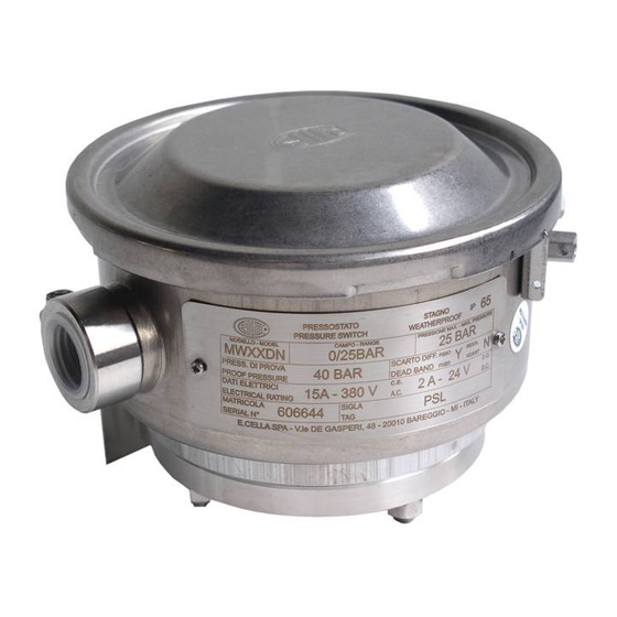
DIAPHRAGM PRESSURE SWITCHES
WEATHERPROOF AND INTRINSICALLY SAFE: MODEL MW
Versions: MWB-MW-MWH-MWG
A
= pressure attachment
B
= cable entry
For surface mounting use two screws M6
WEIGHT 1,8 kg
NOTE: dimensions and weights are not binding unless released on certified drawings.
CAUTION
Before installing, using or carrying out maintenance on the instrument it is necessary to read and understand the indications given
in the attached Instruction Manual.
The instrument must only be installed and maintained by qualified personnel.
INSTALLATION IS TO BE CARRIED OUT ONLY AFTER CHECKING THAT INSTRUMENT CHARACTERISTICS ARE
CONSISTENT WITH PROCESS AND PLANT REQUIREMENTS.
The functional features of the instrument and its degree of protection are shown on the identification plate fixed to the case.
CONTENTS:
1
2
3
4
5
6
7
8
9
10
11
12
13
14
15
SAFETY INSTRUCTIONS FOR USE IN HAZARDOUS ATMOSPHERES.
RECOMMENDATIONS FOR PRESSURE SWITCH SAFE USE.
All data, statements and recommendations supplied with this manual are based on information believed by us to be reliable. As the
conditions of effective use are beyond our control, our products are sold under the condition that the user himself evaluates such
conditions before following our recommendations for the purpose or use foreseen by him.
The present document is the property of ALEXANDER WIEGAND SE &Co and may not be reproduced in any form, nor used for any
purpose other than that for which it is supplied.
INSTRUCTION MANUAL
Dimensions in mm
FLAMEPROOF: MODEL MA
Versions: MAB-MA-MAH-MAG
A
= pressure attachment
B
= cable entry
For surface mounting use four screws M6
WEIGHT 3,2 kg
RELATED DOCUMENT
To authentified document with certificate
N° IECEx PRE 16.0067X
N° IECEx PRE 16.0074X
NI-221WE
REV. 5 12/16
Dimensions in mm
Advertisement
Table of Contents


Need help?
Do you have a question about the mw series and is the answer not in the manual?
Questions and answers
Preciso um orçamento numero de Série/Modelo 85500P3D- MWXXDN