
Subscribe to Our Youtube Channel
Related Manuals for KSB Etaseco


Summary of Contents for KSB Etaseco
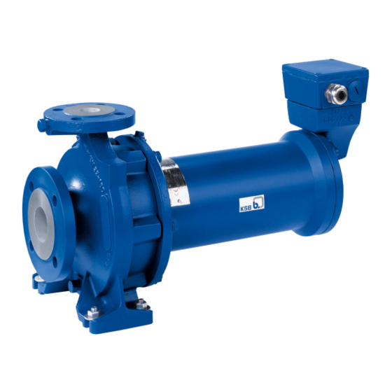
- Page 1 Standardised Water Pump Etaseco/ Etaseco-I Motor Sizes DS 90, DS 112, DS 132 Plain Bearings (SSiC) Three-phase Motor Thermistor Installation/Operating Manual...
- Page 2 All rights reserved. The contents provided herein must neither be distributed, copied, reproduced, edited or processed for any other purpose, nor otherwise transmitted, published or made available to a third party without the manufacturer's express written consent. Subject to technical modification without prior notice. © KSB SE & Co. KGaA, Frankenthal 22/12/2017...
-
Page 3: Table Of Contents
Connecting the potential equalisation conductor................ 26 5.5.3 Connection to power supply ...................... 27 Commissioning/Start-up/Shutdown.................... 33 Commissioning/Start-up .......................... 33 6.1.1 Prerequisites for commissioning/start-up .................. 33 6.1.2 Priming and venting the pump...................... 33 6.1.3 Start-up............................... 34 6.1.4 Checking/changing the direction of rotation .................. 35 Etaseco/ Etaseco-I 3 of 76... - Page 4 Pump set with motor sizes 12 and 22 .................... 62 9.1.2 Pump set with motor sizes 42, 52, 72, 112 and 152 ................. 65 Spare motor unit ............................ 68 EU Declaration of Conformity ...................... 70 Certificate of Decontamination...................... 71 Index .............................. 72 Etaseco/ Etaseco-I 4 of 76...
-
Page 5: Glossary
Shut-off head H₀ The pump is running at rated speed against a closed shut-off element, producing maximum pump pressure. Suction lift line/suction head line The pipeline which is connected to the suction nozzle Etaseco/ Etaseco-I 5 of 76... -
Page 6: General
The order number and order item number uniquely identify the pump (set) and serve as identification for all further business processes. In the event of damage, immediately contact your nearest KSB service centre to maintain the right to claim under warranty. Noise characteristics see (ð Section 4.6, Page 18) 1.2 Installation of partly completed machinery... - Page 7 1 General Symbol Description Step-by-step instructions Note Recommendations and important information on how to handle the product Etaseco/ Etaseco-I 7 of 76...
-
Page 8: Safety
▪ The pump (set) must not be operated on a frequency inverter. ▪ The pump (set) must only be operated within the operating limits described in the other applicable documents. (ð Section 1.4, Page 6) ▪ Only operate pumps/pump sets which are in perfect technical condition. Etaseco/ Etaseco-I 8 of 76... -
Page 9: Personnel Qualification And Training
In addition to the safety information contained in this manual and the intended use, the following safety regulations shall be complied with: ▪ Accident prevention, health and safety regulations ▪ Explosion protection regulations ▪ Safety regulations for handling hazardous substances ▪ Applicable standards, directives and laws Etaseco/ Etaseco-I 9 of 76... -
Page 10: Safety Information For The Operator/User
Never operate the pump (set) outside the limits stated in the data sheet and in this manual. The warranty relating to the operating reliability and safety of the supplied pump (set) is only valid if the equipment is used in accordance with its intended use. Etaseco/ Etaseco-I 10 of 76... -
Page 11: Transport/Temporary Storage/Disposal
1. On transfer of goods, check each packaging unit for damage. 2. In the event of in-transit damage, assess the exact damage, document it and notify KSB or the supplying dealer (as applicable) and the insurer about the damage in writing immediately. -
Page 12: Storage/Preservation
(wooden cover with sealing element). This has to be removed before the unit is used. 3.3 Storage/preservation If commissioning is to take place some time after delivery, we recommend that the following measures be taken for pump (set) storage. Etaseco/ Etaseco-I 12 of 76... -
Page 13: Return To Supplier
4. Always complete and enclose a certificate of decontamination when returning the pump (set). Always indicate any safety and decontamination measures taken. (ð Section 11, Page 71) NOTE If required, a blank certificate of decontamination can be downloaded from the following web site: www.ksb.com/certificate_of_decontamination Etaseco/ Etaseco-I 13 of 76... -
Page 14: Disposal
2. Separate and sort the pump materials, e.g. by: - Metals - Plastics - Electronic waste - Greases and other lubricants 3. Dispose of materials in accordance with local regulations or in another controlled manner. Etaseco/ Etaseco-I 14 of 76... -
Page 15: Description Of The Pump (Set)
▪ Standardised water pump with canned motor Pump for handling toxic, volatile or valuable liquids in environmental engineering and industrial applications. 4.2 Designation Example: Etaseco G X - I 32 - 125.1 / 1 2 Table 4: Designation key Code Description... -
Page 16: Design Details
▪ Thermal class H ▪ Thermal motor protection by PTC thermistors ▪ To IEC 60034-7 ▪ DOL starting ▪ Star-delta starting Automation Automation options: ▪ PumpMeter Can be used for 400 V; motor 42, 52, 72, 112, 152 Etaseco/ Etaseco-I 16 of 76... -
Page 17: Configuration And Function
4 Description of the Pump (Set) 4.5 Configuration and function Fig. 6: Sectional drawing of Etaseco Impeller Bore Plain bearing (impeller end) Support sleeve Plain bearing (motor end) Terminal box Bore Shaft Rotor Stator Integrated power cable Design The hydraulic system and the motor are firmly connected and form a close-coupled unit. -
Page 18: Noise Characteristics
Spatial average; as per ISO 3744 and EN 12639; valid for pump operation in the Q/Qopt = 0.8 - 1.1 range and for non- cavitating operation. If noise levels are to be guaranteed, add +3 dB for measuring and constructional tolerance. Etaseco/ Etaseco-I 18 of 76... -
Page 19: Installation At Site
▷ Observe the permissible minimum bending radius indicated in the data sheet provided by the cable manufacturer or stated on the order-specific outline drawing; if required, contact KSB. 1. Check structural requirements. All structural work required must have been prepared in accordance with the dimensions stated in the outline drawing/general arrangement drawing. -
Page 20: Horizontal Installation
5 Installation at Site Other installation types only after consultation with KSB. 5.3.1 Horizontal installation 5.3.1.1 Installation without baseplate Fig. 7: Horizontal installation ü The installation surface has the required strength and characteristics. ü The installation surface has been prepared in accordance with the dimensions given in the outline drawing/general arrangement drawing. -
Page 21: Vertical Installation
5. Align the pump set with the help of a spirit level placed on the suction nozzle and the motor housing in such a way that the discharge nozzle flange is in vertical position. 6. Use shims for height compensation, if necessary. All shims must lie perfectly flush. Etaseco/ Etaseco-I 21 of 76... -
Page 22: Piping
1. Thoroughly clean, flush and blow through all vessels, pipelines and connections (especially of new installations). 2. Before installing the pump in the piping, remove the flange covers on the suction and discharge nozzles of the pump. Etaseco/ Etaseco-I 22 of 76... -
Page 23: Permissible Forces And Moments At The Pump Nozzles
I, and ∑IM I are the sums of the absolute values of the respective loads acting on the nozzles. Neither the load direction nor the load distribution among the nozzles are taken into account in these sums. Etaseco/ Etaseco-I 23 of 76... -
Page 24: Auxiliary Connections
5 Installation at Site Table 7: Permissible forces and moments at the pump nozzles Size Etaseco G Etaseco S Etaseco C Vmax Hmax tmax Vmax Hmax tmax Vmax Hmax tmax [kN] [kN] [kNm] [kN] [kN] [kNm] [kN] [kN] [kNm] 32-125.1 0.55 3.65... - Page 25 , the power cable connected is a shielded cable of 4 × 1.5 mm². The use of the power cable shield is left to the customer’s discretion. As an option, unshielded cables or cables of 4 × 2.5 mm² can be used. Etaseco/ Etaseco-I 25 of 76...
-
Page 26: Connecting The Potential Equalisation Conductor
▪ Maximum tightening torque: 2 Nm Fig. 16: Screw terminal for potential equalisation Earthing / potential equalisation Motor housing terminal 1. Connecting the potential equalisation optionally provided on the outside of the motor housing is recommended. (ð Section 5.5.1.3, Page 26) Etaseco/ Etaseco-I 26 of 76... -
Page 27: Connection To Power Supply
▷ Observe the technical specifications of the local energy supply companies. 1. Check the available mains voltage against the data on the name plate. 2. Select an appropriate start-up method. NOTE A motor protection device is recommended. Etaseco/ Etaseco-I 27 of 76... - Page 28 ü The motor is wired for delta configuration as indicated on the name plate. Example: Δ/Y 400 V/-- ü Supply voltage from 380 to 420 V 1. Fit bridges as shown below. 2. Connect conductors as shown below. Etaseco/ Etaseco-I 28 of 76...
- Page 29 Y/Δ combination and monitoring device, e.g. motor protection switch 5.5.3.1.2 Version with integrated power cable DANGER Earth conductor not properly connected Danger from electric shock! ▷ Connect the earth conductor to the marked PE terminal in the control cabinet. Etaseco/ Etaseco-I 29 of 76...
- Page 30 Damage to the power cable! ▷ Observe the permissible minimum bending radius indicated in the data sheet provided by the cable manufacturer or stated on the order-specific outline drawing; if required, contact KSB. PE*) Fig. 24: Electrical connection with integrated power cable...
- Page 31 1. Protect the motor against overloading by a thermal time-lag overload protection device in accordance with EN 60439 (VDE 0660) and local regulations (motor protection switch). 2. Set the overload protection device to the rated current specified on the name plate (ð Section 4.3, Page 15) . Etaseco/ Etaseco-I 31 of 76...
- Page 32 Proven monitoring systems: ▪ Pressure switch ▪ Flow control device ▪ Level control unit ▪ cos φ control unit ▪ Current control unit If PTCs are installed in the stator. Etaseco/ Etaseco-I 32 of 76...
-
Page 33: Commissioning/Start-Up/Shutdown
6. For suction head operation: Vent the system up to the discharge-side shut-off element. 7. For suction lift operation: Evacuate the pump and the suction line. The min. permissible pressure is 0.1 bar (absolute). 8. Close all auxiliary connections (barrier fluid, flushing liquid, etc). Etaseco/ Etaseco-I 33 of 76... -
Page 34: Start-Up
4. Immediately after the pump has reached full rotational speed, slowly open the shut-off element in the discharge line and adjust it to the duty point. 5. Adjust barrier fluid supply, if any, in accordance with the data sheet. Etaseco/ Etaseco-I 34 of 76... -
Page 35: Checking/Changing The Direction Of Rotation
2. If the value reached by the pump is more than 10 % below the shut-off head in the characteristic curve, the direction of rotation of the pump set might be incorrect. Etaseco/ Etaseco-I 35 of 76... -
Page 36: Checking The Characteristic Curve/Changing The Direction Of Rotation
Electrical connection work by unqualified personnel Danger of death from electric shock! ▷ Always have the electrical connections installed by a trained and qualified electrician. ▷ Observe regulations IEC 60364. 2. Take safety precautions for work on electric installations. (ð Section 5.5.3, Page 27) Etaseco/ Etaseco-I 36 of 76... -
Page 37: Shut-Off Between Two Operating Periods
▷ Avoid prolonged operation against a closed shut-off element (5 minutes maximum). ▷ Never operate the pump at temperatures exceeding those specified in the data sheet or on the name plate unless the written consent of the manufacturer has been obtained. Etaseco/ Etaseco-I 37 of 76... -
Page 38: Frequency Of Starts
Peak voltage at the motor Û < 1000 V Maximum frequency Rated frequency see data sheet Minimum frequency 50 % of the rated frequency Lower temperatures on request Rated values: see data sheet Lower values on request Etaseco/ Etaseco-I 38 of 76... -
Page 39: Fluid Handled
When the pump handles liquids containing abrasive substances, increased wear of all components in contact with the fluid handled is to be expected. In this case, reduce the intervals commonly recommended for servicing and maintenance. Minimum permissible flow rate Best efficiency point Maximum permissible flow rate Etaseco/ Etaseco-I 39 of 76... -
Page 40: Shutdown/Storage/Preservation
Risk of personal injury from moving parts or escaping fluid! ▷ As soon as the work is complete, re-install and/or re-activate any safety-relevant and protective devices. NOTE If the pump has been out of service for more than one year, replace all elastomer seals. Etaseco/ Etaseco-I 40 of 76... -
Page 41: Servicing/Maintenance
NOTE All maintenance, service and installation work can be carried out by KSB Service or authorised workshops. For contact details please refer to the enclosed "Addresses" booklet or visit "www.ksb.com/contact" on the Internet. -
Page 42: Inspection Work
7.2.2 Inspection work 7.2.2.1 Checking the clearances Fig. 25: Clearances Table 12: Clearances by material Material [mm] [mm] [mm] [mm] [mm] [mm] G, S 0,15... 0,45 0,15... 0,45 0,25... 0,75 0,25... 0,75 Etaseco/ Etaseco-I 42 of 76... - Page 43 2. Measure the insulation resistance of the motor winding to chassis ground. (ð Section 7.2.2.5, Page 44) ð If resistance to chassis ground ≧ 5 MΩ: motor winding in working order. The pump can be re-installed and connected to the power supply (ð Section 5.5.3, Page 27) . Etaseco/ Etaseco-I 43 of 76...
- Page 44 The pump can be connected to the power supply. ð If the electrical resistance to chassis ground < 5 MΩ, contact KSB Service. Version with integrated power cable ü The integrated power cable of the pump set has been disconnected in the control cabinet.
- Page 45 ü The pump set has been removed from the piping if required. ü The power cable at the pump set is visible and freely accessible. 1. Visually inspect the power cable for any damage. 2. If any parts are damaged, contact KSB Service. Earth conductor test DANGER...
-
Page 46: Drainage/Cleaning
Connection 6B (casing drain) 11E (flushing liquid) Draining Depending on the installation type, choose one of the following connections for draining: Table 14: Connections for draining Installation type Connection Horizontal Vertical (motor on top) Vertical (motor below) 6B.4 Etaseco/ Etaseco-I 46 of 76... -
Page 47: Dismantling The Pump Set
Risk of injury! ▷ Always have repair and maintenance work performed by specially trained, qualified personnel. WARNING Hot surface Risk of personal injury! ▷ Allow the pump set to cool down to approx. 35 °C. Etaseco/ Etaseco-I 47 of 76... -
Page 48: Disconnecting The Electrical Connections
Version with integrated power cable ü The information in (ð Section 7.4.1, Page 47) has been observed. 1. Disconnect the power cables from the system power supply. 2. Remove the routed cable from the cable duct (or similar) if applicable. Etaseco/ Etaseco-I 48 of 76... -
Page 49: Removing The Pump Set And Dismantling The Pump Casing
WARNING Possible fluid residues Hazard to persons and the environment! ▷ Wear safety clothing and a protective mask. ▷ Collect and dispose of any fluid residues. 8. Undo nuts 920.01. 9. Remove the pump casing. Etaseco/ Etaseco-I 49 of 76... -
Page 50: Removing The Impeller
7.4.7 Dismantling the bearings Auxiliary device We recommend fastening the rotor to the support surface at the rotor core pack so that the torque required to undo/fasten motor-end bearing sleeve 529.06 can be applied. Etaseco/ Etaseco-I 50 of 76... -
Page 51: Cleaning And Checking The Components
- For disposal open the stator space and completely dismantle the motor unit, if required. 4. Inspect the bores located in the following components for cleanliness and free passage. Clean them, if necessary. - Impeller 230 - Thrust bearing 314.01/.02 Etaseco/ Etaseco-I 51 of 76... -
Page 52: Checking The Motor Unit
Carrying out the maintenance work described below during the warranty period will result in loss of warranty cover. In the event of damage during the warranty period contact KSB. For standard maintenance the motor unit does not need to be completely dismantled. -
Page 53: Reassembling The Pump Set
The connection cable is defective. The motor winding is in working order. ð Insulation resistance < 5 MΩ: The motor winding is defective. The power cable is in working order. 3. If the power cable is defective, have the power cable replaced by KSB Service and reassemble the pump set. Reassembly from step (ð Section 7.4.9, Page 52) 4. -
Page 54: Installing The Bearings
Make sure not to damage the stator can in this process. 4. Fit countersunk head screws 900.72 or hexagon socket head cap screws 914.72. Tighten them with a torque wrench. Observe the tightening torque. (ð Section 7.6, Page 58) Etaseco/ Etaseco-I 54 of 76... -
Page 55: Fitting The Rotor
ü The running surface of the motor-end bearing sleeve has been wetted with a suitable liquid. 1. Carefully insert the rotor into the rotor space until the bearing sleeve (motor end) is held and guided by the bearing bush in bearing carrier 382. Etaseco/ Etaseco-I 55 of 76... -
Page 56: Fitting The Casing Cover/Bearing Bracket Lantern
Observe the tightening torque. (ð Section 7.6, Page 58) 7.5.5 Fitting the impeller ü The notes and steps stated in (ð Section 7.5.1, Page 53) to (ð Section 7.5.4, Page 56) have been observed/carried out. 1. Insert key 940.01 into the shaft keyway. 2. Slip on impeller 230. Etaseco/ Etaseco-I 56 of 76... -
Page 57: Installing The Back Pull-Out Unit In The Pump Casing
2. Subject the pump to a leak test. - Medium: dry compressed air or nitrogen - Pressure: 2 bar - Duration: 30 minutes 3. Apply a leak detection spray to all sealed parts (e.g. casing seals, screw plugs). Etaseco/ Etaseco-I 57 of 76... -
Page 58: Tightening Torques
Table 19: Tightening torques for screw plugs Part No. Description Thread With joint ring Tightening torque Part No. Seal material [Nm] 903.91 Screw plug G 3/8 911.91 DPAF Wet the joint rings (e.g. with a drop of water). Etaseco/ Etaseco-I 58 of 76... -
Page 59: Spare Parts Stock
Spare motor 10 % If applicable If more than 5 identical motors are in operation, we recommend to keep a spare motor on stock instead of the parts bearing this index For size DS 112/132 only Etaseco/ Etaseco-I 59 of 76... -
Page 60: Trouble-Shooting
If problems occur that are not described in the following table, consultation with the KSB customer service is required. A Pump is running, but does not deliver B Pump delivers insufficient flow rate... - Page 61 ▪ Check contact points of impeller and rotor for any damage and reuseability. Replace components if necessary. ✘ ▪ Flow rate too low ▪ Verify minimum flow rate against data sheet. Increase flow rate accordingly. Etaseco/ Etaseco-I 61 of 76...
-
Page 62: Related Documents
Version with integrated power cable Table 22: List of components Part No. Comprising Description Volute casing 502.01 Casing wear ring 902.01 Stud 920.01 903.01/.03 Screw plug 411.01/.03 Joint ring Casing cover 400.19 Gasket 74-5 Separator 903.16 Screw plug Etaseco/ Etaseco-I 62 of 76... - Page 63 Electrical connection for version with terminal box Terminal box 400.81 Gasket 732.10 Holder 914.57 Hexagon socket head cap screw Rotating parts, bearing bush not included Or 914.72 Or 900.72 Or 81-29.04 Or 81-15 Or 914.38 Or 900.38 Etaseco/ Etaseco-I 63 of 76...
- Page 64 9 Related Documents Part No. Comprising Description Cable gland Sealed terminal gland 412.81 O-ring 550.81 Disc 914.85 Hexagon socket head cap screw Electrical connection for version with integrated power cable Power cable Cable 826.01 Cable gland Optional Etaseco/ Etaseco-I 64 of 76...
-
Page 65: Pump Set With Motor Sizes 42, 52, 72, 112 And 152
Joint ring 502.01 Casing wear ring 902.01 Stud 903.01/.03 Screw plug 920.01 Casing cover 400.19 Gasket 902.15 Stud 920.15 Impeller 502.02 Casing wear ring 310.10 310.10 Plain bearing 314.01/.02 Thrust bearing 529.21 Bearing sleeve 950.23 Spring Etaseco/ Etaseco-I 65 of 76... - Page 66 Hexagon socket head cap screw Cable gland Sealed terminal gland 412.81 O-ring 550.81 Disc 914.85 Hexagon socket head cap screw Electrical connection for version with integrated power cable Power cable Or 914.38 Or 900.38 Optional Etaseco/ Etaseco-I 66 of 76...
- Page 67 9 Related Documents Part No. Comprising Description Cable 826.01 Cable gland Etaseco/ Etaseco-I 67 of 76...
-
Page 68: Spare Motor Unit
80-1 Motor unit 412.21/.22/.41/.71 O-ring Motor housing cover 81-15 PE terminal stud 81-29.04 PE terminal 900.38 Countersunk head screw 914.04/.38 Hexagon socket head cap screw 902.04 Stud Or 81-29.04 Or 81-15 Or 914.38 Or 900.38 Etaseco/ Etaseco-I 68 of 76... - Page 69 Sealing element Disc 902.04 Stud 920.04 Hexagon head bolt Or 914.72 Or 900.72 Or power cable Optional on versions with terminal box only Or terminal box Only for motor sizes 42, 52, 72, 112, 132 Optional Etaseco/ Etaseco-I 69 of 76...
-
Page 70: Eu Declaration Of Conformity
Johann-Klein-Straße 9 67227 Frankenthal (Germany) The manufacturer herewith declares that the product: Etaseco (ESO), Etaseco-I (ESO-I), Etaseco-M (ESO-M), Etaseco RVP (ESO RVP) KSB order number: ....................▪ is in conformity with the provisions of the following Directives as amended from time to time: –... -
Page 71: Certificate Of Decontamination
We confirm that the above data and information are correct and complete and that dispatch is effected in accordance with the relevant legal provisions....................................Place, date and signature Address Company stamp Required fields Etaseco/ Etaseco-I 71 of 76... -
Page 72: Index
Spare parts stock 59 Density 39 Special accessories 18 Frequency inverter 30 Speed control 30 Frequency of starts 38 Start-up 34 Storage 13, 40 Impeller type 16 Installation horizontal 20 Tightening torques 58 vertical 20, 21 Transport 11 Installation at site 19 Intended use 8 Misuse 9 Name plate 15 Noise characteristics 18 Etaseco/ Etaseco-I 72 of 76... - Page 76 KSB SE & Co. KGaA Johann-Klein-Straße 9 • 67227 Frankenthal (Germany) Tel. +49 6233 86-0 www.ksb.com...
Need help?
Do you have a question about the Etaseco and is the answer not in the manual?
Questions and answers