Table of Contents
Advertisement
Advertisement
Table of Contents

Related Manuals for KSB Etabloc


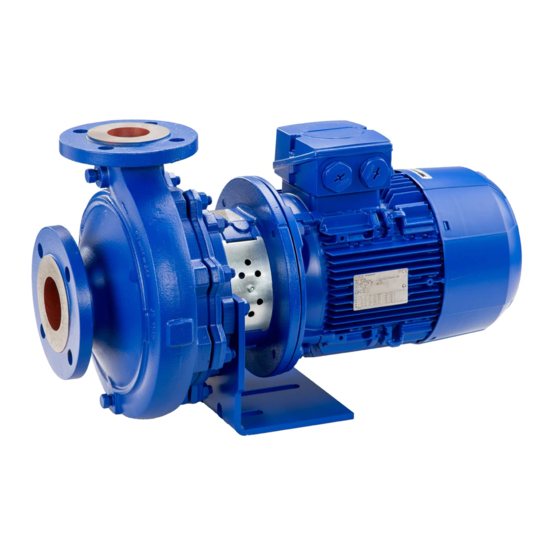
Summary of Contents for KSB Etabloc
- Page 1 Closed-coupled Pump Etabloc Installation/Operating Manual...
- Page 2 All rights reserved. The contents provided herein must neither be distributed, copied, reproduced, edited or processed for any other purpose, nor otherwise transmitted, published or made available to a third party without the manufacturer's express written consent. Subject to technical modification without prior notice. © KSB SE & Co. KGaA, Frankenthal 08/09/2022...
-
Page 3: Table Of Contents
Installing the pump set .......................... 27 Piping ................................ 29 5.3.1 Connecting the piping........................ 29 5.3.2 Permissible forces and moments at the pump nozzles.............. 30 5.3.3 Vacuum balance line.......................... 30 5.3.4 Auxiliary connections......................... 31 Enclosure/insulation ............................ 32 Electrical connection ............................ 32 5.5.1 Setting the time relay ........................ 33 Etabloc 3 of 68... - Page 4 Pump set with single mechanical seal and clamped casing cover .......... 60 9.1.3 Version with double mechanical seal in back-to-back arrangement .......... 62 9.1.4 Version with double mechanical seal in tandem arrangement ............ 63 UK Declaration of Conformity...................... 64 Certificate of Decontamination...................... 65 Index .............................. 66 Etabloc 4 of 68...
-
Page 5: Glossary
Suction lift line/suction head line The pipeline which is connected to the suction nozzle German drinking water regulations to German Environment Agency WRAS Approved by all water suppliers in the UK (WRAS = Water Regulations Advisory Scheme) Etabloc 5 of 68... -
Page 6: General
In the event of damage, immediately contact your nearest KSB service facility to maintain the right to claim under warranty. 1.2 Installation of partly completed machinery To install partly completed machinery supplied by KSB refer to the sub-sections under Servicing/Maintenance. -
Page 7: Key To Safety Symbols/Markings
In conjunction with one of the signal words this symbol indicates a hazard involving electrical voltage and identifies information about protection against electrical voltage. Machine damage In conjunction with the signal word CAUTION this symbol indicates a hazard for the machine and its functions. Etabloc 7 of 68... -
Page 8: Safety
Deficits in knowledge must be rectified by means of training and instruction provided by sufficiently trained specialist personnel. If required, the operator can commission the manufacturer/supplier to train the personnel. Training on the pump (set) must always be supervised by technical specialist personnel. Etabloc 8 of 68... -
Page 9: Consequences And Risks Caused By Non-Compliance With This Manual
▪ Only perform work on the pump set when it has been disconnected from the power supply (de-energised). ▪ The pump (set) must have cooled down to ambient temperature. ▪ Pump pressure must have been released and the pump must have been drained. Etabloc 9 of 68... -
Page 10: Unauthorised Modes Of Operation
The motors fitted by KSB on pumps certified for potentially explosive atmospheres meet this condition. Misuse, malfunctions or non-compliance with the instructions may result in substantially higher temperatures. -
Page 11: Monitoring Equipment
If the pump is to be operated at a higher temperature, the data sheet is missing or if the pump is part of a pool of pumps, contact KSB for the maximum permissible operating temperature. Motor supplied by the... -
Page 12: Transport/Storage/Disposal
1. On transfer of goods, check each packaging unit for damage. 2. In the event of in-transit damage, assess the exact damage, document it and notify KSB or the supplying dealer and the insurer about the damage in writing immediately. -
Page 13: Storage/Preservation
4. Always complete and enclose a certificate of decontamination when returning the pump. Indicate any safety measures and decontamination measures taken. (ð Section 11, Page 65) NOTE If required, a blank certificate of decontamination can be downloaded from the following web site: www.ksb.com/certificate_of_decontamination Etabloc 13 of 68... -
Page 14: Disposal
Collect greases and other lubricants during dismantling. 2. Separate and sort the pump materials, e.g. by: - Metals - Plastics - Electronic waste - Greases and other lubricants 3. Dispose of materials in accordance with local regulations or in another controlled manner. Etabloc 14 of 68... -
Page 15: Description Of The Pump (Set)
1 2 3 4 5 6 7 8 9 10 11 12 13 14 15 16 17 18 19 20 21 22 23 24 25 26 27 28 29 30 31 32 33 34 35 36 37 38 E T B - 0 4 0 - 0 See name plate and data sheet See data sheet Table 6: Designation key Position Code Description Pump type Etabloc Etabloc 15 of 68... - Page 16 EN-GJL-250 / A48 Cl. 35B Design European Regulation (EC) No. 1935/2004 Bottle rinser variant Approved for drinking water to ACS Approved for drinking water to KSB standard Swimming pool variant Gohl (special design) Standard Approved for drinking water to UBA Approved for drinking water to WRAS...
- Page 17 [kW] 0075 0300 1100 Number of motor poles 2 poles 4 poles 6 poles 31-32 Explosion protection With explosion-proof motor Without explosion-proof motor Product generation Etabloc 34-37 Description Fixed speed version Variable speed version, with PumpDrive 2 Etabloc 17 of 68...
- Page 18 Design Design as per European Regulation (EC) No. 1935/2004 Bottle rinser variant Approved for drinking water to ACS Approved for drinking water to KSB standard Swimming pool variant Standard Approved for drinking water to UBA Approved for drinking water to WRAS...
- Page 19 ≥ -20 - ≤ +110 [°C] Q1Q1KGG M7G49 ≥ -20 - ≤ +110 [°C] Q1Q1KGG M7G49 ≥ -20 - ≤ +110 [°C] Q1BVGG ≥ -20 - ≤ +110 [°C] Type of lubrication None Order type Extended standard KSB standard Special design Etabloc 19 of 68...
- Page 20 KSB PumpDrive 2 KSB PumpMeter KSB PumpDrive 2 + KSB PumpMeter KSB Guard Han-Drive 10E Han-Drive 10E + KSB PumpMeter None Version for potentially explosive atmospheres KSB PumpDrive 2 + KSB Guard KSB PumpMeter 2 + KSB Guard KSB PumpDrive 2 + KSB PumpMeter + KSB Guard Product generation Generation B Etabloc 20 of 68...
-
Page 21: Name Plate
4 Description of the Pump (Set) 4.4 Name plate KSB SE & Co. KGaA Johann-Klein-Straße 9 67227 Frankenthal ETB 150-125-250 GB X 10 Etabloc 47132456 Ø 174 mm 9971234567 000100 / 01 Q 30,00 m³/h H 34,00 v 1,0 mm²/s... - Page 22 ▪ Duty type: continuous duty S1 ▪ Thermal class F with temperature sensor, 3 PTC thermistors Explosion-proof design: ▪ KSB surface-cooled IEC three-phase current squirrel-cage motor ▪ Rated voltage (50 Hz) 220 - 240 V / 380 - 420 V ≤ 1.85 kW ▪ Rated voltage (50 Hz) 380 - 420 V / 660 - 725 V ≥ 2.50 kW ▪...
-
Page 23: Installation Types
4 Description of the Pump (Set) 4.6 Installation types Table 9: Installation types (examples) Horizontal installation, Horizontal installation, Vertical fastened below fastened above installation 71-112 132-180 Etabloc 23 of 68... - Page 24 4 Description of the Pump (Set) Horizontal installation, Horizontal installation, Vertical fastened below fastened above installation 200-315 = connection of the pump set to the foundation Etabloc 24 of 68...
-
Page 25: Configuration And Function
(10 and 11), which are supported by a motor housing (5) linked with the pump casing and/or casing cover (3) via the drive lantern (9). Sealing The pump is sealed by a standardised mechanical seal. Etabloc 25 of 68... -
Page 26: Noise Characteristics
Surface sound pressure level as per ISO 3744 and DIN EN ISO 20361 ; valid for a pump operating range of Q/ QBEP = 0.8 - 1.1 and non-cavitating operation. If noise levels are to be guaranteed: Add +3 dB for measuring and constructional tolerance. Etabloc 26 of 68... -
Page 27: Installation At Site
Damage to the pump! ▷ Never install the pump set with the motor foot and the pump foot both fastened to the foundation at the same time. Fastening Installation examples / Installation types (ð Section 4.6, Page 23) Fig. 6: Installing the pump set Etabloc 27 of 68... - Page 28 The motor foot must be supported without transmitting any stresses or strains, but it must not be fastened. Use the support bolt supplied (not supplied for vertical installation). For Etabloc 100-080-400, 125-100-400, 150-125-315, 150-125-400, 200-150-315 and 200-150-400 the pump foot must be supported without transmitting any stresses or strains. The pump foot must not be fastened to the foundation.
-
Page 29: Piping
▷ Remove any impurities from the piping. ▷ If necessary, install a filter. ▷ Observe the information in (ð Section 7.2.2.2, Page 45) . 3. Check that the inside of the pump is free from any foreign objects. Remove any foreign objects. Etabloc 29 of 68... -
Page 30: Permissible Forces And Moments At The Pump Nozzles
Where fluid has to be pumped out of a vessel under vacuum, installing a vacuum balance line is recommended. The following rules apply to vacuum balance lines: ▪ Minimum nominal line diameter 25 mm. ▪ The line extends above the highest permissible fluid level in the vessel. Etabloc 30 of 68... -
Page 31: Auxiliary Connections
Risk of burns! Malfunction of the pump! ▷ Refer to the general arrangement drawing, the piping layout and pump markings (if any) for the quantity, dimensions and locations of auxiliary connections. ▷ Use the auxiliary connections provided. Etabloc 31 of 68... -
Page 32: Enclosure/Insulation
▷ Observe the technical specifications of the local energy supply companies. 1. Check the available mains voltage against the data on the motor name plate. 2. Select an appropriate starting method. NOTE Installing a motor protection device is recommended. Etabloc 32 of 68... -
Page 33: Setting The Time Relay
Hands inside the pump casing Risk of injuries, damage to the pump! ▷ Always disconnect the pump set from the power supply and secure it against unintentional start-up before inserting your hands or other objects into the pump. Etabloc 33 of 68... - Page 34 The motor's direction of rotation must match the arrow indicating the direction of rotation on the pump. 3. If the motor runs in the wrong direction of rotation, check the electrical connection of the motor and the control system, if applicable. Etabloc 34 of 68...
-
Page 35: Commissioning/Start-Up/Shutdown
▷ Provide an appropriate monitoring system. DANGER Risk of potentially explosive atmosphere by incompatible fluids mixing in the auxiliary piping Risk of burns! Explosion hazard! ▷ Make sure that the barrier fluid or quench liquid are compatible with the fluid handled. Etabloc 35 of 68... -
Page 36: Start-Up
Excessive temperatures due to dry running or excessive gas content in the fluid handled Explosion hazard! Damage to the pump set! ▷ Never operate the pump set without liquid fill. ▷ Prime the pump as per operating instructions. ▷ Always operate the pump within the permissible operating range. Etabloc 36 of 68... -
Page 37: Checking The Shaft Seal
Heat build-up inside the pump Damage to the shaft seal! ▷ Depending on the type of installation, the pump set requires sufficient after- run time – with the heat source switched off – until the fluid handled has cooled down. Etabloc 37 of 68... -
Page 38: Operating Limits
DANGER Formation of a potentially explosive atmosphere inside the pump Explosion hazard! ▷ When draining tanks take suitable measures to prevent dry running of the pump (e.g. fill level monitoring). Etabloc 38 of 68... -
Page 39: Ambient Temperature
▷ Do not re-start the pump set before the pump rotor has come to a standstill. For compliance with UK Equipment and Protective Systems Intended for Use in Potentially Explosive Atmospheres Regulations 2016. Higher ambient temperature possible in individual cases, see data sheet and name plate. Etabloc 39 of 68... -
Page 40: Fluid Handled
ü Sufficient fluid is supplied for the functional check run of the pump. 1. For prolonged shutdown periods, start up the pump (set) regularly between once a month and once every three months for approximately five minutes. Best efficiency point Etabloc 40 of 68... -
Page 41: Returning To Service
▷ As soon as the work is completed, properly re-install and re-activate any safety- relevant devices and protective devices. NOTE If the equipment has been out of service for more than one year, replace all elastomer seals. Etabloc 41 of 68... -
Page 42: Servicing/Maintenance
Fluids handled, consumables and supplies which are hot and/or pose a health hazard Risk of injury! ▷ Observe all relevant laws. ▷ When draining the fluid take appropriate measures to protect persons and the environment. ▷ Decontaminate pumps which handle fluids posing a health hazard. Etabloc 42 of 68... -
Page 43: Servicing/Inspection
NOTE All maintenance work, service work and installation work can be carried out by KSB Service or authorised workshops. For contact details refer to the enclosed "Addresses" booklet or visit "www.ksb.com/contact" on the Internet. - Page 44 After commissioning, increased temperatures may occur at grease-lubricated rolling element bearings due to the running-in process. The final bearing temperature is only reached after a certain period of operation (up to 48 hours depending on the conditions). Etabloc 44 of 68...
-
Page 45: Inspection Work
7.2.2.2 Cleaning filters CAUTION Insufficient inlet pressure due to clogged filter in the suction line Damage to the pump! ▷ Monitor contamination of filter with suitable means (e.g. differential pressure gauge). ▷ Clean filter at appropriate intervals. Etabloc 45 of 68... -
Page 46: Drainage/Cleaning
▷ Use suitable transport devices, lifting equipment and lifting tackle to move heavy assemblies or components. Always observe the safety instructions and information. (ð Section 7.1, Page 42) For any work on the motor, observe the instructions of the relevant motor manufacturer. Etabloc 46 of 68... -
Page 47: Preparing The Pump Set
In the event of damage you can always contact our service departments. NOTE All maintenance work, service work and installation work can be carried out by KSB Service or authorised workshops. For contact details refer to the enclosed "Addresses" booklet or visit "www.ksb.com/contact" on the Internet. -
Page 48: Removing The Back Pull-Out Unit
3. Undo hexagon nuts 920.01 and 914.22, if any, on drive lantern 341. 4. Remove casing cover 161 from drive lantern 341. 5. Remove the stationary assembly of the mechanical seal (mating ring) from casing cover 161. 6. Remove and dispose of gasket 400.75. Etabloc 48 of 68... -
Page 49: Reassembling The Pump Set
▷ Use an original motor or a motor of identical design from the same manufacturer. ▷ The permissible temperature limits at the motor flange and motor shaft must be higher than the temperatures generated by the pump. (Contact KSB for temperatures). WARNING... -
Page 50: Installing The Mechanical Seal
8. Fit the rotating assembly of the mechanical seal (primary ring) on shaft sleeve 523. Observe the following installation dimension b for mechanical seals with installation length L to EN 12756 (design KU): Fig. 9: Installation dimension b of mechanical seal Impeller Shaft sleeve Mechanical seal Casing cover Etabloc 50 of 68... -
Page 51: Fitting The Impeller
(on variant with a clamped casing cover) at volute casing 102. 7.5.5 Mounting the motor DANGER Incorrect shaft connection Explosion hazard! ▷ Connect the shafts between pump and motor as described in this manual. Shaft unit see data sheet. Etabloc 51 of 68... - Page 52 Fig. 11: Removing the lock washers 901.50 Hexagon head bolts 931.95 Lock washer 4. Pull both lock washers 931.95 out of the groove in shaft 210. 5. Tighten hexagon head bolts 901.50. 6. Fit and tighten hexagon nuts 920.11. Etabloc 52 of 68...
-
Page 53: Tightening Torques
7.6 Tightening torques UG1352931_D01_101/06 Fig. 12: Tightening points, version with bolted casing cover UG1352931_D01_103/02 Fig. 13: Tightening points, version with clamped casing cover UG1602828_CDK_D02/01 Fig. 14: Tightening points, version with baseplate Fig. 15: Tightening points, vertical installation with vent valve Etabloc 53 of 68... -
Page 54: Spare Parts Stock
Refer to the name plate for all data. Also specify the following data: ▪ Part number and description (ð Section 9.1, Page 58) ▪ Quantity of spare parts ▪ Shipping address ▪ Mode of dispatch (freight, mail, express freight, air freight) Etabloc 54 of 68... -
Page 55: Recommended Spare Parts Stock
Casing wear ring (set) 50 % Shaft sleeve 50 % 400.10 Gasket 150 % 400.75 Gasket 150 % 400.15 Gasket 150 % 411.15 Joint ring 150 % 412.15 O-ring 150 % For double mechanical seal If any Etabloc 55 of 68... -
Page 56: Trouble-Shooting
If problems occur that are not described in the following table, consultation with the KSB service is required. A Pump delivers insufficient flow rate B Motor is overloaded... - Page 57 Increase the minimum flow rate. ✘ ✘ - Incorrect inflow of circulation liquid. Increase the free cross-section. ✘ ✘ - Transport lock has not been removed Remove transport lock from the shaft groove. from the shaft groove. Etabloc 57 of 68...
-
Page 58: Related Documents
200-150-250 50-32-250.1 65-40-250 65-50-250 80-65-250 100-80-315 125-100-315 150-125-315 200-150-315 50-32-200 65-40-315 65-50-315 80-65-315 100-80-400 125-100-400 150-125-400 200-150-400 50-32-250 [Supplied in packaging units only] Fig. 16: Model with single mechanical seal and bolted casing cover, without pump foot Etabloc 58 of 68... - Page 59 Disc Fluid priming and venting Some individual components might not be applicable, depending on the pump size and material. Not available for model with support foot For region A, C only For shaft unit 55 only Etabloc 59 of 68...
-
Page 60: Pump Set With Single Mechanical Seal And Clamped Casing Cover
Table 26: This illustration applies to the following pump sizes: 40-25-160 50-32-125.1 65-40-125 65-50-125 80-65-125 100-80-160 125-100-160 150-125-200 200-150-200 50-32-160.1 65-40-160 65-50-160 80-65-160 100-80-200 125-100-200 50-32-125 50-32-160 [Supplied in packaging units only] Fig. 18: Model with single mechanical seal and clamped casing cover, without pump foot Etabloc 60 of 68... - Page 61 Shaft sleeve Fluid drain 550.95 Disc Fluid priming and venting Some individual components might not be applicable, depending on the pump size and material. Not available for model with support foot For shaft unit 55 only Etabloc 61 of 68...
-
Page 62: Version With Double Mechanical Seal In Back-To-Back Arrangement
932.05 Circlip 562.02 Parallel pin Table 29: Auxiliary connections Part No. Description Part No. Description External barrier water outlet External barrier water inlet Some individual components might not be applicable, depending on the pump size and material. Etabloc 62 of 68... -
Page 63: Version With Double Mechanical Seal In Tandem Arrangement
Intermediate ring 931.95 Lock washer Shaft sleeve Table 31: Auxiliary connections Part No. Description Part No. Description Quench liquid outlet Quench liquid inlet Some individual components might not be applicable, depending on the pump size and material. Etabloc 63 of 68... -
Page 64: Declaration Of Conformity
67227 Frankenthal (Germany) This UK Declaration of Conformity is issued under the sole responsibility of the manufacturer. The manufacturer herewith declares that the product: Etabloc, Etabloc SYT, Etaline, Etaline SYT, Etaline Z, Etachrom B, Etachrom L, Etanorm, Etanorm SYT, Etanorm V, Etaprime L, Etaprime B KSB order number: .................... -
Page 65: Certificate Of Decontamination
We confirm that the above data and information are correct and complete and that dispatch is effected in accordance with the relevant legal provisions....................................Place, date and signature Address Company stamp Required field Etabloc 65 of 68... -
Page 66: Index
Spare parts stock 55 Start-up 37 General assembly drawing 59, 61, 62, 63 Storage 13, 41 Impeller type 22 Temperature limits 11 Installation 27 Installation on a foundation 28 Tightening torques 54 Installation at site 27 Transport 12 Intended use 8 Warnings 7 Key to safety symbols/markings 7 Warranty claims 6 Etabloc 66 of 68... - Page 68 KSB SE & Co. KGaA Johann-Klein-Straße 9 • 67227 Frankenthal (Germany) Tel. +49 6233 86-0 www.ksb.com...
Need help?
Do you have a question about the Etabloc and is the answer not in the manual?
Questions and answers