Table of Contents
Advertisement
Quick Links
Advertisement
Table of Contents

Related Manuals for KSB Etanorm V


Summary of Contents for KSB Etanorm V
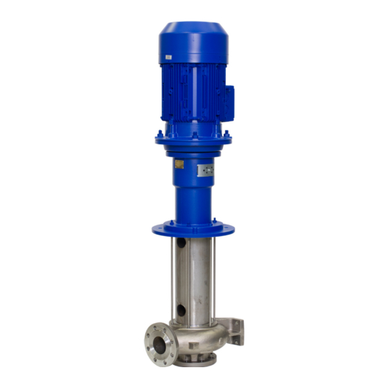
- Page 1 Vertical Low-pressure Pump Etanorm V Design W Operating Manual...
- Page 2 All rights reserved. The contents provided herein must neither be distributed, copied, reproduced, edited or processed for any other purpose, nor otherwise transmitted, published or made available to a third party without the manufacturer's express written consent. Subject to technical modification without prior notice. © KSB SE & Co. KGaA, Frankenthal 23/06/2022...
-
Page 3: Table Of Contents
Setting the time relay ........................ 27 5.5.2 Connecting the motor ........................ 27 Checking the direction of rotation........................ 27 Commissioning/Start-up/Shutdown.................... 29 Commissioning/Start-up .......................... 29 6.1.1 Prerequisites for commissioning/start-up .................. 29 6.1.2 Priming and venting the pump...................... 29 6.1.3 Start-up............................... 29 6.1.4 Shutdown ............................ 30 Etanorm V 3 of 62... - Page 4 Trouble-shooting.......................... 52 Related Documents .......................... 53 General drawings with list of components.................... 53 9.1.1 General assembly drawing with list of components for W design .......... 53 UK Declaration of Conformity...................... 57 Certificate of Decontamination...................... 58 Index .............................. 59 Etanorm V 4 of 62...
-
Page 5: Glossary
Pump Machine without drive, additional components or accessories Pump set Complete pump set consisting of pump, drive, additional components and accessories Suction lift line/suction head line The pipeline which is connected to the suction nozzle Etanorm V 5 of 62... -
Page 6: General
In the event of damage, immediately contact your nearest KSB service facility to maintain the right to claim under warranty. 1.2 Installation of partly completed machinery To install partly completed machinery supplied by KSB refer to the sub-sections under Servicing/Maintenance. -
Page 7: Key To Safety Symbols/Markings
In conjunction with one of the signal words this symbol indicates a hazard involving electrical voltage and identifies information about protection against electrical voltage. Machine damage In conjunction with the signal word CAUTION this symbol indicates a hazard for the machine and its functions. Etanorm V 7 of 62... -
Page 8: Safety
Deficits in knowledge must be rectified by means of training and instruction provided by sufficiently trained specialist personnel. If required, the operator can commission the manufacturer/supplier to train the personnel. Etanorm V 8 of 62... -
Page 9: Consequences And Risks Caused By Non-Compliance With This Manual
▪ Only perform work on the pump set when it has been disconnected from the power supply (de-energised). ▪ The pump (set) must have cooled down to ambient temperature. ▪ Pump pressure must have been released and the pump must have been drained. Etanorm V 9 of 62... -
Page 10: Unauthorised Modes Of Operation
Never operate the pump (set) outside the limits stated in the data sheet and in this operating manual. The warranty relating to the operating reliability and safety of the pump (set) supplied is only valid if the equipment is used in accordance with its intended use. (ð Section 2.2, Page 8) Etanorm V 10 of 62... -
Page 11: Transport/Storage/Disposal
1. On transfer of goods, check each packaging unit for damage. 2. In the event of in-transit damage, assess the exact damage, document it and notify KSB or the supplying dealer and the insurer about the damage in writing immediately. -
Page 12: Storage/Preservation
CAUTION Wet, contaminated or damaged openings and connections Leakage or damage to the pump! ▷ Clean and cover pump openings and connections as required prior to putting the pump into storage. Etanorm V 12 of 62... -
Page 13: Return To Supplier
2. Separate and sort the pump materials, e.g. by: - Metals - Plastics - Electronic waste - Greases and other lubricants 3. Dispose of materials in accordance with local regulations or in another controlled manner. Etanorm V 13 of 62... -
Page 14: Description Of The Pump (Set)
See name plate and data sheet See data sheet Table 5: Designation key Position Code Description Pump type ETNV Etanorm V 5-16 Size, e.g. Nominal suction nozzle diameter [mm] Nominal discharge nozzle diameter [mm] 1251 Nominal impeller diameter [mm] Pump casing material Stainless steel 1.4408 / A743CF8M... -
Page 15: Name Plate
Mat.-No. 01216137 ZN 3823-217 Fig. 5: Name plate (example) Etanorm V - design W Type series code, size and version Type series KSB order No., order item No. and Flow rate consecutive No. Kinematic viscosity of the fluid Material number (if applicable) handled... -
Page 16: Design Details
▪ Volute casing with integrally cast pump feet ▪ Replaceable casing wear rings Drive ▪ KSB surface-cooled IEC three-phase current squirrel-cage motor ▪ Type of construction IM V1 ▪ Rated voltage (50 Hz) 220-240 V / 380-420 V ≤ 2.20 kW ▪ Rated voltage (50 Hz) 380-420 V / 660 - 725 V ≥ 3.00 kW ▪... -
Page 17: Design And Function
4 Description of the Pump (Set) For operating an Etanorm V on a frequency inverter which has not been configured via the KSB selection tool consultation with KSB is required. For operating pump sets at immersion depths > 1000 mm with variable-speed system consultation with KSB is required for the selection. -
Page 18: Noise Characteristics
050-032-160 ✘ Surface sound pressure level to ISO 3744, valid for a pump operating range of Q/QBEP = 0.8 - 1.1 and non- cavitating operation. If noise levels are to be guaranteed: Add +3 dB for measuring and constructional tolerance. Etanorm V 18 of 62... -
Page 19: Dimensions And Weights
Casing cover design Clamped Bolted 100-080-400 ✘ 125-100-400 ✘ 150-125-315 ✘ 150-125-400 ✘ 200-150-315 ✘ 200-150-400 ✘ 4.10 Dimensions and weights For dimensions and weights refer to the general arrangement drawing/outline drawing of the pump/pump set. Etanorm V 19 of 62... -
Page 20: Installation At Site
3. Align the upper flange of the drive lantern with a spirit level. 4. Make adjustments between cover plate and tank edge, if required. If the pump is installed without suction strainer, observe a minimum distance B to the tank floor. Etanorm V 20 of 62... - Page 21 5 Installation at Site Fig. 7: Distance from the floor Table 10: Distance from the floor in [mm] ≥80 ≥80 ≥100 ≥100 ≥100 ≥150 ≥150 Etanorm V 21 of 62...
- Page 22 The axial position is correct when shaft 210 and the motor shaft have been assembled in the position they are closest to each other. This is the case when the motor shaft end abuts the coupling inside the coupling sleeve. Etanorm V 22 of 62...
- Page 23 5. Check the position of the slot of locking ring 515. Make sure that the slot of locking ring 515 is above and aligned with the shaft/ coupling slot (see Fig. "Position of the locking ring"). Etanorm V 23 of 62...
-
Page 24: Piping
Incorrect earthing during welding work at the piping Destruction of rolling element bearings (pitting effect)! ▷ Never earth the electric welding equipment on the pump or baseplate. ▷ Prevent current flowing through the rolling element bearings. Etanorm V 24 of 62... -
Page 25: Permissible Forces And Moments At The Pump Nozzles
1000 1421 050-032-160.1 1000 1421 050-032-200.1 1000 1421 050-032-250.1 1000 1421 050-032-125 1000 1421 050-032-160 1000 1421 050-032-200 1000 1421 050-032-250 1000 1421 065-040-125 1000 1250 1803 065-040-160 1000 1250 1803 065-040-200 1000 1250 1803 Etanorm V 25 of 62... -
Page 26: Electrical Connection
Damage to the power supply network, short circuit! ▷ Observe the technical specifications of the local energy supply companies. 1. Check the available mains voltage against the data on the name plate. 2. Select an appropriate start-up method. Etanorm V 26 of 62... -
Page 27: Setting The Time Relay
▷ Never retrofit with a variable speed system pump sets which were originally selected for a specific rated speed. ▷ If you would like to retrofit pumps with a variable speed system, contact KSB. NOTE In compliance with IEC 60034-8, three-phase motors are always wired for clockwise rotation (looking at the motor shaft stub). - Page 28 The motor's direction of rotation must match the arrow indicating the direction of rotation on the drive lantern/bearing lantern. 3. If the motor is running in the wrong direction of rotation, check the electrical connection of the motor and the control system, if applicable. Etanorm V 28 of 62...
-
Page 29: Commissioning/Start-Up/Shutdown
1. Close or slightly open the shut-off element in the discharge line. 2. Start up the motor. 3. Immediately after the pump has reached full rotational speed, slowly open the shut-off element in the discharge line and adjust it to comply with the duty point. Etanorm V 29 of 62... -
Page 30: Shutdown
(DOL, star-delta, moments of inertia, etc). If the starts are evenly spaced over the period indicated, the following limits serve as orientation for start-up with the discharge-side gate valve slightly open: Etanorm V 30 of 62... -
Page 31: Minimum Permissible Speed
6.2.4.4 Abrasive fluids When the pump handles fluids containing abrasive substances, increased wear of the hydraulic system and the shaft seal are to be expected. In this case, reduce the commonly recommended inspection intervals. Best efficiency point Etanorm V 31 of 62... -
Page 32: Shutdown/Storage/Preservation
If the equipment has been out of service for more than one year, replace all elastomer seals. 6.5 Cleaning the pump set NOTE The pump is splash-proof as it is designed without bearings above the cover plate. Etanorm V 32 of 62... - Page 33 6 Commissioning/Start-up/Shutdown NOTE For the electric motor observe the manufacturer´s product literature. Etanorm V 33 of 62...
-
Page 34: Servicing/Maintenance
NOTE All maintenance work, service work and installation work can be carried out by KSB Service or authorised workshops. For contact details refer to the enclosed "Addresses" booklet or visit "www.ksb.com/contact" on the Internet. -
Page 35: Inspection Work
If the clearances need to be checked, remove the impeller. If the clearance gap is larger or smaller than permitted (see the following table), replace casing wear rings 502.01 and/or 502.02. The clearances given refer to the diameter. Etanorm V 35 of 62... -
Page 36: Drainage/Cleaning
▷ Always have repair work and maintenance work performed by specially trained, qualified personnel. WARNING Hot surface Risk of injury! ▷ Allow the pump set to cool down to ambient temperature. Shaft unit see data sheet. Etanorm V 36 of 62... -
Page 37: Preparing The Pump Set
In the event of damage you can always contact our service departments. NOTE All maintenance work, service work and installation work can be carried out by KSB Service or authorised workshops. For contact details refer to the enclosed "Addresses" booklet or visit "www.ksb.com/contact" on the Internet. -
Page 38: Removing The Riser
Damage to the plain bearing parts! ▷ Take appropriate care when removing/installing shock-sensitive SiC plain bearing parts (bearing sleeve, bearing bush in the bearing cartridge). 5. Remove shaft 210 with SiC bearing sleeve 529.16. 6. Undo and remove nuts 920.14/920.06. Etanorm V 38 of 62... -
Page 39: Reassembling The Pump Set
4. Place bearing housing 350 on bearing cartridge 381.01 and fasten it with bolts 901.33 at casing cover 161. Take care not to damage O-ring 412.24 when fitting bearing housing 350. 5. Fasten the plain bearing assembly to casing cover 161 with bolts 901.33. Etanorm V 39 of 62... -
Page 40: Installing The Volute Casing And Support Column
8. Slide disc 550.46 onto shaft 210 and into the locating fit of drive lantern 341. 9. Fit support column 712 on drive lantern 341. 10. Slide spacer sleeve 525, if any, onto shaft 210. 11. Fit key 940.01 in shaft 210. Etanorm V 40 of 62... - Page 41 14. Slide the impeller onto shaft 210. 15. Fit disc 550.95 on the impeller hub and tighten impeller 230 with nut 920.95. 16. Place volute casing 102 on casing cover 161 and fasten it with nuts 920.01. Etanorm V 41 of 62...
-
Page 42: Installing The Riser
7.6.1 Tightening torques for the pump Fig. 12: Tightening points Table 17: Tightening torques for bolted/screwed connections at the pump Position Thread Tightening torque [Nm] M12 × 1,5 M16 × 1,5 M24 × 1,5 M30 × 1,5 Etanorm V 42 of 62... -
Page 43: Spare Parts Stock
Disc Coupling 914.24 Hexagon socket head cap screw 920.95 930.95 Safety device 940.01 211 - pump shaft Pump shaft Locking ring 550.95 Disc 211 only for pumps with motor 110/112 For shaft unit 25 only Etanorm V 43 of 62... -
Page 44: Immersion Depths
Permissible immersion depth at rated speed ✓ (maximum speed) Permissible immersion depth with PumpDrive (permissible maximum speed for operation on a frequency inverter) Combination impermissible Table 21: Overview of immersion depths for Etanorm V (2-pole) Etanorm V 50 Hz 60 Hz Immersion depth... - Page 45 7 Servicing/Maintenance Etanorm V 50 Hz 60 Hz Immersion depth Immersion depth 2 poles [kW] (Maximum speed [rpm]) [kW] (Maximum speed [rpm]) 050-032-125 112M ✓ (3600) ✓ (3000) ✓ ✓ ✓ ✓ ✓ (3600) ✓ ✓ ✓ ✓ 050-032-125 132S ✓ (3600) ✓ (3000) ✓...
- Page 46 7 Servicing/Maintenance Etanorm V 50 Hz 60 Hz Immersion depth Immersion depth 2 poles [kW] (Maximum speed [rpm]) [kW] (Maximum speed [rpm]) 065-040-250 180M ✓ (3500) ✓ (3000) ✓ ✓ ✓ 065-040-250 200L ✓ (3500) ✓ (3000) ✓ ✓ ✓ 065-050-125 100L ✓...
- Page 47 7 Servicing/Maintenance Etanorm V 50 Hz 60 Hz Immersion depth Immersion depth 2 poles [kW] (Maximum speed [rpm]) [kW] (Maximum speed [rpm]) 100-080-200 200L ✓ (3500) ✓ (3000) ✓ ✓ ✓ 41,5 ✓ (3500) ✓ (3000) ✓ ✓ ✓ 100-080-200 225M ✓ (3500) ✓ (3000) ✓...
- Page 48 Permissible immersion depth at rated speed ✓ (maximum speed) Permissible immersion depth with PumpDrive (permissible maximum speed for operation on a frequency inverter) Combination impermissible Table 23: Overview of immersion depths for Etanorm V (4-pole) Etanorm V 50 Hz 60 Hz Immersion depth...
- Page 49 7 Servicing/Maintenance Etanorm V 50 Hz 60 Hz Immersion depth Immersion depth 4 poles [kW] (Maximum speed [rpm]) [kW] (Maximum speed [rpm]) 065-050-200 100L ✓ (3500) ✓ (3000) ✓ (1800) ✓ (1500) ✓ 3,45 ✓ (3500) ✓ (3000) ✓ (1800) ✓ 065-050-200 112M ✓...
- Page 50 7 Servicing/Maintenance Etanorm V 50 Hz 60 Hz Immersion depth Immersion depth 4 poles [kW] (Maximum speed [rpm]) [kW] (Maximum speed [rpm]) 100-080-200 160L ✓ (3500) ✓ (3000) ✓ (1800) ✓ (1500) ✓ ✓ 17,3 ✓ (3500) ✓ (3000) ✓ (1800) ✓...
- Page 51 7 Servicing/Maintenance Etanorm V 50 Hz 60 Hz Immersion depth Immersion depth 4 poles [kW] (Maximum speed [rpm]) [kW] (Maximum speed [rpm]) 150-125-200 132M ✓ (3500) ✓ (2100) ✓ (2100) ✓ (1800) ✓ (1500) ✓ (1500) 150-125-200 160M ✓ (3500) ✓ (2100) ✓ (2100) ✓ (1800) ✓ (1500) ✓ (1500) 12,6 ✓ (3500) ✓ (2100) ✓ (2100) ✓ (1800) ✓...
-
Page 52: Trouble-Shooting
If problems occur that are not described in the following table, consultation with the KSB service is required. A Pump delivers insufficient flow rate B Motor is overloaded... -
Page 53: Related Documents
920.11 901.57 920.75 68-3.02 901.11 920.14 400.06 68-3.01 920.06 920.34 550.46 561.29 529.16 901.33 412.24 381.01 400.10 932.42 502.02 903.01 901.39 920.19 940.01 400.16 502.01 550.95 903.03 930.95 920.95 Fig. 13: General assembly drawing Etanorm V, design W Etanorm V 53 of 62... - Page 54 Material variant CC; shaft units WS 25 / 35 / 55 902.01 914.24 920.01 Motor connection Bolted casing cover Material variants GG / CC; shaft units WS 25 / 35; motors Material variants GG / CC; shaft units WS 25 / 35 / 55 100 / 112 Etanorm V 54 of 62...
- Page 55 Joint ring Tie bolt 412.24 O-ring 914.24 Hexagon socket head cap screw 502.01/.02 Casing wear ring 920.01/.06/.11/.14/.19/.34/.75 /.95 For WS_55 only For WS_25 only On pumps without cover plate only Assembly aid or transport lock Etanorm V 55 of 62...
- Page 56 9 Related Documents Part No. Description Part No. Description Spacer ring 930.95 Safety device Locking ring 932.41 /.42 Circlip Spacer sleeve 940.01 529.16 Bearing sleeve 2x for WS_55 Etanorm V 56 of 62...
-
Page 57: Declaration Of Conformity
This UK Declaration of Conformity is issued under the sole responsibility of the manufacturer. The manufacturer herewith declares that the product: Etabloc, Etabloc SYT, Etaline, Etaline SYT, Etaline Z, Etachrom B, Etachrom L, Etanorm, Etanorm SYT, Etanorm V, Etaprime L, Etaprime B KSB order number: .................... -
Page 58: Certificate Of Decontamination
We confirm that the above data and information are correct and complete and that dispatch is effected in accordance with the relevant legal provisions....................................Place, date and signature Address Company stamp Required field Etanorm V 58 of 62... -
Page 59: Index
Fluid handled Tightening torques 42 Density 31 Transport 11 Frequency of starts 31 Function 17 Warnings 7 Warranty claims 6 Impeller type 16 Installation 20 Installation at site 20 Intended use 8 Key to safety symbols/markings 7 Name plate 15 Noise characteristics 18 Operating limits 30 Order number 6 Other applicable documents 6 Etanorm V 59 of 62... - Page 62 KSB SE & Co. KGaA Johann-Klein-Straße 9 • 67227 Frankenthal (Germany) Tel. +49 6233 86-0 www.ksb.com...
Need help?
Do you have a question about the Etanorm V and is the answer not in the manual?
Questions and answers