Table of Contents
Advertisement
Quick Links
Advertisement
Table of Contents

Subscribe to Our Youtube Channel
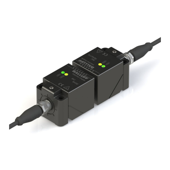
Summary of Contents for Balluff BIC 1B0-IT1A7-Q40KFU-SM4A4A
- Page 1 BIC 1B0-IT1A7-Q40KFU-SM4A4A BIC 2B0-IT1A7-Q40KFU-SM4A5A User's Guide...
-
Page 2: Table Of Contents
6.2 Connection Time Technical Data 7.1 Base LED 1 / LED 2 Mechanical Data Electrical Data Operating Conditions Pin Assignment 7.2 Remote LED 1 / LED 2 Mechanical Data Electrical Data Operating Conditions Pin Assignment Appendix 8.1 Ordering Information www.balluff.com... -
Page 3: General
Balluff BIC-System BIC 1l1-P2A05-M12MM-BPX0-003-M45A BIC 2l1-P2A05-M12MF-BPX0-003-M44A General 1.1. Structure of the This guide is arranged so that one chapter builds upon the other. guide Chapter 1: General Chapter 2: Safety ……… 1.2. Typographical The following typographical conventions are uses in this manual. -
Page 4: Safety
Risk of burning on hot surfaces! The sensing surface heats up even under normal operating conditions. Keep hands and objects away from the sensing surface. Metallic objects are not permitted in the in the zones defined by A and B or between the sensing surfaces of the Base and Remote. Fire hazard! www.balluff.com... -
Page 5: Protection From Electromagnetic Fields
(operating) limits may apply. Note In the interest of continuous improvement of the product, Balluff GmbH reserves the right to change the technical data of the product and the content of these instructions at any time without notice. www.balluff.com... -
Page 6: System Overview
The BIC system can only be operated using Balluff IO-Link masters. Reliable operation on IO-Link masters from other manufacturers cannot be guaranteed. When using a Profibus IO-Link master module from Balluff GmbH only modules having the following hardware version are compatible. -
Page 7: Installation
Balluff Inductive Coupler BIC 1B0-IT1A7-Q40KFU-SM4A4A (Base) BIC 2B0-IT1A7-Q40KFU-SM4A5A (Remote) Installation 4.1 Mutual To prevent mutual interference with adjacent Bases or Remotes, the specified minimum Interference distances must be adhered to. Type A (mm) BIC 1B0-IT1A7-Q40KFU-SM4A4A ≥ 200 BIC 2B0-IT1A7-Q40KFU-SM4A5A ≥ 200 4.2 Installation in... -
Page 8: Distances / Offset
Installation 4.3 Distances / Offset Type A (mm) B (mm) BIC 1B0-IT1A7-Q40KFU-SM4A4A ≤ 5 ≤ 5 BIC 2B0-IT1A7-Q40KFU-SM4A5A ≤ 5 ≤ 5 The system may be operated at a greater distance and/or offset. What is defining is the power transmitted by the system. -
Page 9: 180° Rotation Of The Connector Insert
Balluff Inductive Coupler BIC 1B0-IT1A7-Q40KFU-SM4A4A (Base) BIC 2B0-IT1A7-Q40KFU-SM4A5A (Remote) Installation 4.5 180° Rotation of The connector insert on the base and remote can be rotated 180°. the Connector To do this follow the disassembly steps (1 through 6) described in the following. After the Insert connector insert is rotated (step 7), subsequent reassembly is performed in reverse order. -
Page 10: Energy Transmission
The max. available peak current is 5A. Note If a larger average output current is required at a resulting ambient temperature, active cooling can be used to reduce the temperature surrounding the BIC so that more current is available. www.balluff.com... -
Page 11: Output Current Of The Bic In Space
Balluff Inductive Coupler BIC 1B0-IT1A7-Q40KFU-SM4A4A (Base) BIC 2B0-IT1A7-Q40KFU-SM4A5A (Remote) Energy Transmission Output Current of the BIC in Space System ≤ 20% distance mm] ≤ 40% ≤ 60% ≤ 80% ≤ 100% System offset [mm] Note The measurement which the derating curve as a function of distance is based was performed with no angular offset. -
Page 12: Io-Link Communication
This means there is no IODD for the BIC Q40 bidirectional. Note The BIC system can only be operated using Balluff IO-Link masters. Using IO-Link masters produced by other manufacturers can lead to disruptions in communication. -
Page 13: Technical Data
Balluff Inductive Coupler BIC 1B0-IT1A7-Q40KFU-SM4A4A (Base) BIC 2B0-IT1A7-Q40KFU-SM4A5A (Remote) Technical Data 7.1 Base LED 1 / LED 2 Indicator Function Green, static Supply voltage OK LED1 Green, inverted flashing IO-Link communication OK Yellow off Pin 2 turned off Yellow, static... -
Page 14: Pin Assignment
GND, 0 V C/Q, IO-Link Note The digital I/O signal on Pin 2 can only be sent when the BIC is in IO-Link mode. If the IO-Link master is in standard I/O mode, the signal is not sent. www.balluff.com... -
Page 15: Remote
Balluff Inductive Coupler BIC 1B0-IT1A7-Q40KFU-SM4A4A (Base) BIC 2B0-IT1A7-Q40KFU-SM4A5A (Remote) Technical Data 7.2 Remote LED 1 / LED 2 Indicator Function Green, static Supply voltage OK LED1 Green, inverted flashing IO-Link communication OK Yellow on Pin 2 high LED2 Yellow off... -
Page 16: Pin Assignment
GND, 0 V C/Q, IO-Link Note The digital I/O signal on Pin 2 can only be sent when the BIC is in IO-Link mode. If the IO-Link master is in standard I/O mode, the signal is not sent. www.balluff.com... -
Page 17: Appendix
Balluff Inductive Coupler BIC 1B0-IT1A7-Q40KFU-SM4A4A (Base) BIC 2B0-IT1A7-Q40KFU-SM4A5A (Remote) Appendix 8.1 Ordering Product name Order code Information BIC 1B0-IT1A7-Q40KFU-SM4A4A BIC007F BIC 2B0-IT1A7-Q40KFU-SM4A5A BIC007H www.balluff.com... - Page 18 Balluff GmbH Schurwaldstrasse 9 D-73765 Neuhausen a.d.F. Germany Phone +49 7158 173-0 Fax +49 7158 5010 www.balluff.com balluff@balluff.de...


Need help?
Do you have a question about the BIC 1B0-IT1A7-Q40KFU-SM4A4A and is the answer not in the manual?
Questions and answers