Table of Contents
Advertisement
Advertisement
Chapters
Table of Contents
Troubleshooting

Subscribe to Our Youtube Channel
Related Manuals for Eaton EABO-6106


Summary of Contents for Eaton EABO-6106
- Page 1 Eaton® Transmission Service Manual EA(B)O-6X06 January 2018 Rev. 1...
-
Page 2: Table Of Contents
Table of Contents 1. General Information ......... 5 Introduction .......... 5 Warnings and Precautions ....6 Characteristics and Identification ..7 Gear Ratio ........... 9 Lubrication ......... 10 Tightening Torques and Sealants ..12 Precautions........15 Special Tools ........18 Exploded View. - Page 3 Table of Contents 3. Disassembly and Assembly ....41 Transmission Disassembly ....42 Front Case ......... 54 Rear Case ......... 56 Shift Yokes and Rails ......59 Synchronizers ........66 Input Shaft ......... 69 Mainshaft ........... 71 Countershaft ........93 Transmission Assembly .....
-
Page 4: General Information
CEP 13270 - Valinhos, São Paulo - Brazil SAC 0800 170 551 www.eaton.com.br pecasouvidor@eaton.com NOTE: Eaton reserves the right to make modifications in its products and to change specifications included in this manual at any time without previous notice. EA(B)O-6X06 1. General Information... -
Page 5: Warnings And Precautions
The description and specifications contained in this service publication are current at the time of printing. Eaton Corporation reserves the right to discontinue or modify its models and/or procedures and to change specifications at any time without notice. -
Page 6: Characteristics And Identification
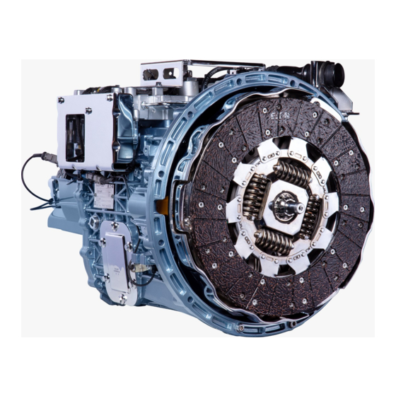
Characteristics and Identification Characteristics of the Automated Transmission The Eaton EA(B)O-6X06 automated transmission is basically a conventional ES family mechanical transmission with 06 forward speeds and 1 reverse speed. The EA(B)O-6X06 is designed to be a fully automated transmission, providing full clutch displacement and control functionality. - Page 7 Characteristics and Identification Model Designation All Eaton transmissions are identified by the model designation and serial number. This information is stamped on the identification plate fixed to the transmission case. EA(B)O - 6X06 A Eaton Gear ratio Automated Forward speeds...
-
Page 8: Gear Ratio
Gear Ratio Gear Ratio EA(B)O-6106/6206A EA(B)O-6106/6206B Torque Lb.ft Ratio Ratio Input Shaft (I) 1.52 1,52 Countershaft (C) Countershaft (C) 6,19 6,19 Mainshaft (M) Countershaft (C) 3,39 3,39 Mainshaft (M) Countershaft (C) 2,08 2,08 Mainshaft (M) Countershaft (C) 1,33 1,33 Mainshaft (M) Countershaft (C) Direct 1,00... -
Page 9: Lubrication
Eaton transmissions are designed so that all the internal parts operate in an oil circulating bath, created by the motion of gears and shafts. Thus, all parts are properly lubricated if the following procedures are closely followed: 1. - Page 10 Lubrication Oil level check Refilling Before checking oil level, clean case area around filler plug and if necessary, add enough oil to maintain the proper oil level. CAUTION! Do not mix lubricant of Correct Oil Level different types and brands, as this may cause incompatibility issues.
-
Page 11: Tightening Torques And Sealants
Tightening Torques and Sealants The correct application of adhesives (threadlockers) and sealing compounds (sealants) is important to assure a proper assembly and to avoid leakages. Tightening capscrews, plugs and nuts to the proper torque is important to prevent them from loosening and to avoid oil leakage, assuring a long transmission life. - Page 12 M12 x 1.0 Pivot pin 19-26 (14-19) thread and contact face* 3/4”-14 NPTF Oil fill plug 20-34 (15-25) Apply Loctite 570 (Eaton E677) Apply Dow Corning 780 sealant onto 1/8"-27 NPTF breather 6-10 (4-7) thread and contact face* M6x1.0-6.5 Socket screw...
- Page 13 Loctite 570 (Eaton E677) Adhesive and Sealants: • Dow Corning 780 (Eaton E680) Chemical adhesives can fulfill more than one function: 1. Thread locking, which prevents loose screws by vibration or improper torque. 2. Screw lock and seal, preventing loose screws while ensuring that no lubricant leakage will occur through the holes.
-
Page 14: Precautions
Precautions Synchronizer assemblies Precautions during disassembly and assembly Avoid bad handling of synchronizer assemblies. Either drops or bumps when disassembling or assembling In order to prevent damage to transmission may cause them to lock. parts during initial gear movement, it is important when assembling the transmission, to lubricate gear bearings, Housings needle roller bearings, non sealed... - Page 15 Parts replacement assemblies When replacement is necessary, use only genuine Eaton transmission parts to assure continued Check carefully gear teeth for wear, pitting, chipping performance and extended life from the transmission. and cracks. If gear teeth show areas where the case...
- Page 16 Precautions Oil seals and snap rings Any oil seal, snap ring, etc. damaged during maintenance, should be replaced by a new one. Replacement of oil seals and snap rings is cheaper when unit is disassembled than a premature overhaul to replace these parts in a future time.
-
Page 17: Special Tools
Special Tools Special Tools Throughout this manual, several transmission maintenance procedures are performed using special tools specifically recommended for this purpose. These special tools are required for properly servicing the transmission and its use will prevent damages to the transmission and its components. In addition, the use of these tools is important to prevent personal injuries and to preserve the safety of the mechanic. -
Page 18: Description
Special Tools Ref. # Tool Description Ref. # Tool Description Puller, countershaft EEA-17103 Puller spindle EEA-17134 bearings (use with EEA-17103) Puller support, Puller, bearing cups EEA-17107 mainshaft rear (use with EEA-17144) EEA-17135 bearing cup (use with EEA-17136) EEA-17110 Puller, oil seal EEA-17136 Puller, bearing cups Puller adapter,... - Page 19 Special Tools Ref. # Tool Description Ref. # Tool Description Device to block EEA-17503 mainshaft output EEA-17200 Stand, transmission yoke Device to block mainshaft output Stand mounting plate, EEA-17504 flange (use with EEA- EEA-17203 transmission (use 17503) with EEA-17200) Support for workbench, Device, countershaft disassembly...
-
Page 20: Exploded View
Exploded Views Transmission and Control Assembly explo001-18 1. Base transmission without 2F. Clamp 57. Spacer control and shields (includes 2G. M8 x 1.25 x 25 screw 58. Flat washer items 70 to 230) 50. Bracket (lower) 59. Screw 2. Electro-hydraulic control unit 51. -
Page 21: Maximum Pressure Valve
Exploded Views Electro-Hydraulic Control Unit (Part 1) explo002-18 3. Valve block 12. Pressure accumulator 350cc 21. Repair kit - reservoir O-ring (includes item 13) 4. Maximum pressure valve (in. 22. Repair kit - electric motor cludes item 5) 13. O-ring (includes items 20 and 23) 5. -
Page 22: Hydraulic Pump Screw 5.4-5.6 (4.0-4.2)
Exploded Views Electro-Hydraulic Control Unit (Part 2) explo003-18 30. Repair kit - shift piston gaskets 37. Repair kit - clutch actuator tube 44. Repair kit - selection (includes items 31 and 32) (includes item 36) chamber cover (includes items 45 and 47) 31. - Page 23 Exploded Views Shift Yokes and Rails explo004-18 70. Shift rail front support 80. Shift yoke pad 92. 3rd/4th Shift rail 71. 1st/2nd Shift block 81. Gear selector 93. 3rd/4th Shift yoke (includes item 94) 72. Roll pin 82. M8 x 1.0 x 18.5 Torx screw 94.
-
Page 24: M8 X 1.25 X 20 Screw
Exploded Views Front Case explo005-18 110. Front case 120. M6 x 1.0 x 6.5 Socket screw 130. Oil seal 111. PTO cover 121. M8 x 1.5 x 25 Screw 131. M8 x 1.25 x 16 Screw 112. M10 x 1.5 x 16 Screw 122. - Page 25 Exploded Views Rear Case explo006-18 140. Rear case 147. Shift actuator plug 155. Reverse idle gear shaft retaining plate 141. Bracket 148. M8 x 1.25 x 45 Screw 156. M8 x 1.25 x 20 Screw 142. M8 x 1.25 x 25 Screw 149.
- Page 26 Exploded Views Input Shaft and Mainshaft explo007-18 170. Oil baffle 183. Snap ring 196. Thrust washer 171. Bearing cup and cone 184. Ball 197. 2nd Speed gear 172. Input shaft 185. Thrust washer 198. Needle roller bearing 173. 5th Speed synchronizer cone 186.
- Page 27 Exploded Views Input Shaft and Mainshaft (continued) explo007-18 208. Reverse sliding clutch assy. 210. Shim - 0.275 / 0.325 mm 210. Shim - 0.960 / 1.040 mm 209. Bearing cup and cone 210. Shim - 0.362 / 0.438 mm 210. Shim - 1.060 / 1.140 mm 210.
- Page 28 Exploded Views Countershaft and Reverse Idle Gear explo008-18 220. Bearing cup and cone 226. Shim - 0.087 / 0.113 mm 226. Shim - 1.060 / 1.140 mm 221. Countershaft drive gear 226. Shim - 0.175 / 0.225 mm 226. Shim - 1.160 / 1.240 mm 222.
-
Page 29: Operation
2. Operation Power Flow The transmission must efficiently transfer the engine’s power or torque to the vehicle’s driveline. It is essential to know what takes place in the transmission during torque transfer when troubleshooting or making repairs. Gears and Synchronizers Identification 11 12 13 14 ESO-6106/6206/fluxo 1. - Page 30 Power Flow How the transmission works 1. Torque from the engine is transferred, through 4. The torque along the countershaft (22) is the clutch, to the transmission`s input shaft (1). transmitted to all the gears of the mainshaft (14), The direction of the rotation is the same as of the assembled on needle roller bearings.
- Page 31 Power Flow 1st Speed ESO-6106/6206/fluxo1 2nd Speed ESO-6106/6206/fluxo2 2. Operation EA(B)O-6X06 01/2018 Rev. 1...
- Page 32 Power Flow 3rd Speed ESO-6106/6206/fluxo3 4th Speed ESO-6106/6206/fluxo4 EA(B)O-6X06 2. Operation 01/2018 Rev. 1...
- Page 33 Power Flow 5th Speed The 5th speed in this transmission is a direct drive speed. This designation is due to the fact that in this speed the input shaft, although it drives the countershaft together, transfers the engine torque directly to the mainshaft, without any gear reduction.
- Page 34 Power Flow Reverse Speed 1. When the reverse speed gear is shifted, the 3. As a result of the reverse idle gear (15) in this torque is transferred from the input shaft (1) to the engagement, the rotation of the mainshaft (14) countershaft (22) performing the first reduction (3 in the reverse speed is counterclockwise.
-
Page 35: Troubleshooting
Troubleshooting The following chart presents some transmission malfunctions with their most common causes and possible solutions. Problem Probable cause Possible solution Reference Transmission Incorrect idle speed Adjust idle speed Instructions in the noise when in adjustment vehicle’s manual neutral Improper or Replace disc Instructions in the damaged clutch... - Page 36 Troubleshooting Problem Probable cause Possible solution Reference Transmission Worn or damaged Replace damaged parts Instructions in the noise with flywheel bushing vehicle’s manual shifted gears or bearing (continued) Vibration from Verify and repair as Instructions in the other vehicle per vehicle’s manual vehicle’s manual components (drive shaft, mounts, yoke)
- Page 37 Troubleshooting Problem Probable cause Possible solution Reference Hard shifting Worn or damaged Replace damaged parts Instructions in this (continued) shifting system manual components (yokes, nylon pads, bars, shift blocks) Improper end play Adjust end play Mainshaft and on mainshaft or countershaft end countershaft play adjustment, in this...
- Page 38 Troubleshooting Problem Probable cause Possible solution Reference Transmission Excessive axial Adjust clearance Mainshaft end play slips out of clearance on main adjustment, in this gears shaft gears manual (continued) Worn or damaged Replace gear Instructions in this clutching gear teeth manual Worn or damaged Replace damaged parts...
- Page 39 Troubleshooting Problem Probable cause Possible solution Reference Double shifting Double gear Reassemble system Instructions in this shifting interlock manual system assembled improperly 2. Operation EA(B)O-6X06 01/2018 Rev. 1...
-
Page 40: Disassembly And Assembly
3. Disassembly and Assembly CAUTION: Whenever you use a vise to secure The section “General Information” contains important transmission components during service, for information and specifications to be used when servicing example shafts, gears, etc., protect the jaws the transmission. with an aluminum angle or other soft material to When disassembling, inspect all components for wear prevent damage to the part. -
Page 41: Transmission Disassembly
Transmission Disassembly Install the mounting plate EEA-17203 (1) on the transmission stand EEA-17200 (2) and install the transmission on the mounting plate with the electro- hydraulic control unit facing up, securing the transmission to the plate through the front case with at least three capscrews. - Page 42 Transmission Disassembly 0002-18 1 - Unlock 2 - Disconnect axially 3 - Do not tilt the connector when disconnecting Remove the four Allen screws securing the TCU to the bracket and remove the TCU. 6944 Unscrew the two screws securing the TCU’s lower bracket to the flange of the transmission rear case.
- Page 43 Transmission Disassembly Unscrew the ground strap retaining screw and remove the strap and both the upper and lower TCU brackets. If necessary, remove the four screws securing the TCU upper bracket to the lower bracket and remove the upper bracket and the four rubber mounts. 6947 Disconnect the wire harness from the clutch actuator position sensor.
- Page 44 Transmission Disassembly 15. With a T40 Torx wrench, remove the six retaining Torx screws securing the electro-hydraulic control unit to the transmission and remove the control unit. NOTE: To break the seal and make easy to remove the electro-hydraulic control unit, use a pry bar underneath the existing tab on the control unit valve block and, then, pry the unit upward.
- Page 45 Transmission Disassembly 20. With an 11mm hex socket, remove the three capscrews securing the shift rails’ front support. 6934 21. On the transmission model having an output yoke, install the special tool EEA-17503 to block the output yoke (Figure A). On the transmission model having an output flange instead of the yoke, install the special tool EEA-17503 with tool EEA-17504 to block the mainshaft (Figure B).
- Page 46 Transmission Disassembly 24. With a 27mm hex socket, remove the shift actuator. 5974 6956 25. With a 27mm hex socket, remove the speedometer sensor. 6961 26. On the stand, set the transmission vertically with the rear case facing up. 27. With an 11mm hex socket, remove the two capscrews securing the shift rails’...
- Page 47 Transmission Disassembly 28. With an 11mm hex socket, remove sixteen capscrews securing the rear case to the front case, being thirteen above (Figure A) and three from underneath (Figure B) the flange. 6964 - Figura A 6966 - Figura B 29.
- Page 48 Transmission Disassembly 31. With a 9mm hex socket, unscrew the eight retaining screws and remove the reverse idle gear cover. NOTE: With a soft hammer, gently tap on the cover to break the seal. 6972 32. Remove the reverse idle gear from its housing, being careful to prevent the needle roller bearing from falling underneath.
- Page 49 Transmission Disassembly 36. Remove the speedometer rotor. 6978 37. With a 13mm hex socket, remove the two pivot pins of the 5th/6th shift yoke, one at each side of the case. 6988 6989 38. With a T40 Torx wrench, remove the retaining Torx screws from the selection lever (1) and gear selector (2).
- Page 50 Transmission Disassembly 39. Disengage all gears, putting them in neutral position. 40. Remove retaining roll pin from shift and selection block. 6004 41. Remove the main shift rail, by pulling it up. As an option, use the tool EEA-17140. NOTE: Be careful when removing the shift rail as the gear selector block, selection lever and the shift block will come out of the rail when it is pulled up.
- Page 51 Transmission Disassembly 45. With a hoist, lift shafts and shift rails assembly holding the input shaft with one hand to hold the shaft in place. 6460a 46. With the special base EEA-17505 already placed on the workbench, position the shafts and shift rails assembly on the base, and lower the shafts fitting the input shaft and countershaft into their housings in the device.
- Page 52 Transmission Disassembly 48. Remove the 5th/6th shift yoke. 6483 49. Remove the shift rails’ rear support. 6485 50. Detach shift rails and yokes from the mainshaft and countershaft. 51. Remove the mainshaft, countershaft and input shaft from the special base and take them apart. 6497 EA(B)O-6X06 3.
-
Page 53: Front Case
Front Case Disassembly Position the front case with its internal side facing up. If necessary, with a 5mm Allen wrench, remove the oil intake retaining screw and remove the oil intake. 6475 Using special tool EEA-17136, remove the countershaft front bearing cup (1). Using special tools EEA-17107 and EEA-17144 (not shown), remove together: the oil baffle (installed underneath the input shaft front bearing cup) and the... - Page 54 Front Case Assembly NOTE: Clean the parts thoroughly and remove any residue of sealant from the parts’ contact surfaces prior to assembly. Carefully clean the bearing housings and cups prior to assembly. With the internal side of the front case facing up, assemble the new oil baffle (1) in the input shaft front bearing cup housing.
-
Page 55: Rear Case
Rear Case Disassembly Position the rear case with its internal side facing up. Using special tools EEA-17136 and EEA-17137 (1), remove the rear bearing cup from the countershaft and remove the end play shims. 6130 6129 Using special tools EEA-17135, EEA-17138 and EEA- 17136, remove the mainshaft rear bearing cup, together with the end play adjusting shims. - Page 56 Rear Case Using a lever, remove the mainshaft rear oil seal from the outside of the case, or hit the seal from inside. NOTE: • The rear oil seal will be damaged during disassembly. Replace it with a new one during assembly.
- Page 57 Rear Case Assembly NOTE: Clean the parts thoroughly and remove any residue of sealant from the parts’ contact surfaces prior to assembly. Properly support the rear case with its internal side facing Carefully clean bearing housings and cups prior to assembly.
-
Page 58: Shift Yokes And Rails
Shift Yokes and Rails Disassembly The speed shifting system of the EA(B)O-6X06 box has gears positioning and interlocking devices located in the front support of the shift yokes and rails assembly. These devices are made of springs and balls actuating on notches on the shift rails that once disassembled should be reassembled very carefully to guarantee its proper functioning. - Page 59 Shift Yokes and Rails Remove the reverse gear shift rail and its respective ball. 6163a Remove the 1st / 2nd gear shift rail. 6164 At last, remove the 3rd / 4th gear shift rail. 6166 Remove balls, pins and springs that are still inside the rails’...
- Page 60 Shift Yokes and Rails Assembly If removed, assemble the yokes, shift blocks and the 1st speed and reverse speed switch actuators in their respective rails, observing the correct assembly sides and positions. Use the notches at the ends mounted on the front support as a reference for the balls in the rails, as shown in the picture aside.
- Page 61 Shift Yokes and Rails After the pins, insert eight 9.5 mm diameter balls, four on each side. NOTE: Use grease to keep the balls in their housings. 6172 Assemble the 1st / 2nd gear shift rail while maintaining the balls in their housings with your finger in the position of the 3rd / 4th gear shift rail.
- Page 62 Shift Yokes and Rails 9. Install the positioner spring. 6505 10. Install the positioner plug and tighten it to a torque of 19 – 26 N.m (14 – 19 lb.ft). NOTE: Apply thread-locker Loctite 262 in the plug thread. 6506 11.
- Page 63 Shift Yokes and Rails 13. Install one 9.5 mm diameter ball, the spring and the positioner plug. Tighten the plug to a torque of 19 – 26 N.m (14 – 19 lb.ft) NOTE: Apply threadlocker Loctite 262 in the plug thread.
- Page 64 Shift Yokes and Rails 17. In the hole connecting the 5th / 6th gear shift rail to the reverse gear shift rail, install one 7.9 mm diameter ball, a spring, one 7.9 mm diameter ball and another spring, in this order. NOTE: Use grease to keep the balls in their housings.
-
Page 65: Synchronizers
Synchronizers NOTE: Synchronizers sets are disassembled and assembled during the mainshaft disassembly and assembly, whose instructions in this manual provide the necessary details. Characteristics EA(B)O-6X06 transmissions use two types of synchronizer sets, all mounted on the mainshaft: • Synchronizer with synchronizing rings of the “Tricone” type, used in the 1st and 2nd speed gear •... - Page 66 Synchronizers Synchronizer with single-type rings Synchronizer ring Key (3x) Sliding clutch (synchronizer sleeve) 6263a 6069a Synchronizer cones The synchronizer cone of the 4th, 5th and 6th speed gears, on which the respective synchronizer ring works, is removable and mounted on splines. The gears of the other speeds have the synchronizer cone integrated into the gear itself.
- Page 67 6074 6277 EFM II coating EFM II (Eaton Friction Material) is a special coating used in some synchronizer rings to increase its lifetime. On the EA(B)O-6X06 transmission model, the following synchronizer rings have the EFM II coating: the single-type ring and the outer ring in the Tricone-type synchronizer ring.
-
Page 68: Input Shaft
Input Shaft Disassembly Remove the 5th gear synchronizer cone (1). Remove the oil baffle (2) from inside its housing. NOTE: The oil baffle will be damaged when disassembled. Replace it with a new one during assembly. 6293 Remove the input shaft front bearing cone using the special tool EEA-17128. - Page 69 Input Shaft Assembly Position the input shaft in a bench press with the front end facing up. Install the front bearing cone using the special tool EEA- 17004. NOTE: If needed, heat the bearing to 120°C to facilitate the installation 7010 Install a new oil baffle (1) inside the 5th gear synchronizer cone (2).
-
Page 70: Mainshaft
Mainshaft Disassembly Remove the 5th speed synchronizer cone. 6064 Remove the “pocket” bearing snap ring. 6067 Remove the sleeve and the three keys of the 5th and 6th speed synchronizer. NOTE: Pay attention not to drop and lose the keys. 6069 Place the mainshaft in vertical position on a work bench with the “pocket”... - Page 71 Mainshaft Using the special tool EEA-17131 supported in the lower face of the 6th speed gear synchronizer cone, remove together: the cone, the 6th speed synchronizer ring, the 5th and 6th speed synchronizer hub and the “pocket” bearing cone. 6071a 6071 Remove the 6th speed gear.
- Page 72 Mainshaft Remove the thrust washer and the positioning ball. 6078 10. Remove together: the 4th speed synchronizer ring, the synchronizer cone and the 4th speed gear. 6079 11. Remove the two needle bearings of the 4th speed gear. 6080 12. Remove the 3rd and 4th speed synchronizer hub snap ring.
- Page 73 Mainshaft 13. Remove the sleeve and the three keys of the 3rd and 4th speed synchronizer. NOTE: Pay attention not to drop and lose the keys. 6083 14. Place the protecting device (1) on the mainshaft “pocket” bearing end to protect the bearing seat. Now, invert the shaft position and place this end (with the protecting device) in the tool EEA-17506 (2), placing the shaft with the rear (yoke) end facing up.
- Page 74 Mainshaft 17. Remove the double needle bearing of the reverse speed gear. 6092 18. Remove the thrust washer snap ring. 6093 19. Remove the thrust washer and the positioning ball. 6094 20. Remove the 1st speed gear. 6096 EA(B)O-6X06 3. Disassembly and Assembly 01/2018 Rev.
- Page 75 Mainshaft 21. Remove the two needle bearings of the reverse speed gear. 6097 22. Remove the 1st speed synchronizer ring (tricone) assembly. 6099 6098 23. Remove the 1st and 2nd speed synchronizer assembly snap ring. 6100 24. Remove the sleeve and the three keys of the 1st and 2nd speed synchronizer.
- Page 76 Mainshaft 25. Place the mainshaft in a press with the yoke end facing up and supported by the 2nd speed gear. CAUTION! Make sure that the gear face is properly supported on the press base. 26. Press the mainshaft down and remove together: the 1st and 2nd speed synchronizer hub, the 2nd speed synchronizer ring (tricone) assembly and the 2nd speed gear.
- Page 77 Mainshaft 29. Place the mainshaft on the work bench once again, with the “pocket: end facing up and supported on the special tool. 30. Remove the double needle bearing of the 3rd speed gear. 6113 31. Remove the thrust washer snap ring. 6114 32.
- Page 78 Mainshaft 34. Remove the 1st and 2nd speed synchronizer hub snap ring. 6119 EA(B)O-6X06 3. Disassembly and Assembly 01/2018 Rev. 1...
- Page 79 Mainshaft Assembly Place the mainshaft in the vertical position on a work bench, with the front (“pocket”) end facing up and the rear (yoke) end supported on the special tool EEA-17506. Install the 1st and 2nd speed synchronizer hub snap ring in the front groove of the spline.
- Page 80 Mainshaft Install the second 1st and 2nd speed synchronizer hub snap ring. 6219 Install the 1st speed synchronizer ring (tricone) outer ring, with the teeth side facing up, matching the ridges on the ring to the slots on the hub. 6227 6220 Install the 1st speed synchronizer ring (tricone) middle...
- Page 81 Mainshaft Rotate the ring until the ridges snap onto the elongated holes in the hub. 6203 6227 10. Install the two needle bearings of the 1st speed gear. NOTE: Lubricate the bearings with oil for the gearbox. 6228 11. Install the 1st speed gear with the cone side facing the synchronizer hub.
- Page 82 Mainshaft 13. Install the positioning ball of the 1st speed gear thrust washer. 6233 6234 14. Install the 1st speed gear thrust washer, aligning the slot on the washer with the positioning ball. 6236 15. Install the thrust washer snap ring. 6237 16.
- Page 83 Mainshaft 17. Install the reverse speed gear with the teeth side facing 6239 18. Heat the reverse speed coupling hub to 140°C and, with special tool EEA-17029 and a hammer, mount the hub in its position in the shaft, until the hub touches the snap ring.
- Page 84 Mainshaft 21. Install the three keys and the 1st and 2nd speed synchronizer sleeve on the synchronizer hub. NOTE: Align the detent grooves for the keys on the sleeve to the key slots on the hub. 6246 6248 22. Install the 2nd speed synchronizer ring (tricone) outer ring, with the teeth side facing up, matching the ridges on the ring to the slots on the hub.
- Page 85 Mainshaft 26. Install the two needle bearings of the 2nd speed gear. NOTE: Lubricate the bearings with oil for the gearbox. 6252 27. Install the 2nd speed gear with the cone side facing the synchronizer hub. 28. Turn the gear until the tabs on the tricone synchronizer ring snap onto the elongated holes in the gear.
- Page 86 Mainshaft 31. Install the thrust washer snap ring. 6077 32. Install the double needle bearing of the 3rd speed gear. NOTE: Lubricate the bearings with oil for the gearbox. 6257 33. Install the 3rd speed gear with the cone side facing up. 6258 34.
- Page 87 Mainshaft 35. Heat the 3rd and 4th speed synchronizer hub to 140°C and, with the special tool EEA-17029 and a hammer, mount the hub in its position in the shaft. During installation of the hub, align and fit the slots on the hub to the ridges on the synchronizer ring.
- Page 88 Mainshaft 39. Install the two needle bearings of the 4th speed gear. NOTE: Lubricate the bearings with oil for the gearbox. 6271 40. Install the 4th speed gear with the cone side facing the synchronizer hub. 6272 41. Install the positioning ball of the thrust washer. 6273 42.
- Page 89 Mainshaft 43. Install the 4th speed gear thrust washer snap ring. 6275 44. Install the two needle bearings of the 6th speed gear. NOTE: Lubricate the bearings with oil for the gearbox. 6276 45. Install the 6th speed gear with the cone side facing the synchronizer hub.
- Page 90 Mainshaft 47. Heat the 5th and 6th speed synchronizer hub to 140°C and, with the special tool EEA-17029 and a hammer, mount the hub in its position in the shaft. During installation of the hub, align and fit the slots on the hub to the ridges on the synchronizer ring.
- Page 91 Mainshaft 51. Install the 5th speed synchronizer ring with the teeth side facing up, matching the ridges on the ring to the slots on the hub. 6292 3. Disassembly and Assembly EA(B)O-6X06 01/2018 Rev. 1...
-
Page 92: Countershaft
Countershaft Disassembly With special tool EEA-17134 with EEA-17103 (not shown), remove the front bearing cone. 6124 With special tool EEA-17134 with EEA-17103 (not shown), remove the rear bearing cone. 6123 Place the countershaft vertically in a press, with the front end facing up. Supporting the countershaft by the lower face of the drive gear (1), press the shaft down and remove the drive gear. - Page 93 Countershaft Assembly Position the countershaft vertically in a press with the front end facing up and supported by the lower face of the 2nd speed gear (machined on the countershaft). Position the 3rd speed gear (4) on the shaft with the most prominent side of the flange facing up and, with a proper tubular device on the gear, press the shaft and install the 3rd speed gear.
-
Page 94: Transmission Assembly
Transmission Assembly NOTE: • Thoroughly clean casings and any previous signs of sealants or adhesives on their contact surfaces, as well as any residue of thread locker on threaded holes and bolts. • See instructions for proper sealant application in the topic “Tightening Torques and Sealants” in this manual. - Page 95 Transmission Assembly NOTE: Disengage all gears, putting them in neutral position. Attach the shift rails set, as assembled before in this manual, to the mainshaft and countershaft assembly, fitting the 1st/2nd and 3rd/4th shift yokes into their respective sliding sleeves. 6497a 6492a Install the shift rails’...
- Page 96 Transmission Assembly Install the 5th/6th shift yoke, fitting the yoke pads into the sliding sleeve and the pin into the shift block hole. 6483 Using a Hellerman-type strap or wire, tie the shafts and shift rails assembly so that they do not come loose during its moving and installation into the front transmission case.
- Page 97 Transmission Assembly 11. Place the front case with its front side (bell housing) facing down on the stand mounting bracket and secure the case with at least three capscrews. 12. With a hoist, lift shafts and shift rails assembly from the special base and position the assembly over the front case.
- Page 98 Transmission Assembly 16. Install the two roll pins of the reverse shift yoke. 6008 17. Install the main shift rail at the same time that the gear selector, selection lever and the shift block are installed, making the rail to pass through their holes. Fit the lower end of the rail into the front support.
- Page 99 Transmission Assembly 20. From the front side of the transmission, install the three retaining capscrews of the shift rails’ front support. Use an 11mm hex socket. NOTE: Apply Dow Corning 780 sealant onto the capscrew contact surfaces. Tighten capscrews to the torque of 19-26 N.m (14-19 Lb.ft) 6934 21.
- Page 100 Transmission Assembly 23. Install the speedometer rotor. 6978 24. Clean the contact faces of the front and rear cases, removing any signs of the old sealant. CAUTION! If either the mainshaft or countershaft end play has not yet been adjusted, DO NOT apply sealant to the housing faces at this point and provisionally install the rear case with its retaining screws.
- Page 101 Transmission Assembly 26. Install the sixteen rear case retaining capscrews to the front case, being thirteen above (Figure A) and three underneath (Figure B) the flange. Tighten capscrews in a criss-cross tightening sequence to the torque of 19-26 N.m (14-19 Lb.ft). Use an 11mm hex socket. 6964 - Figura A 6966 - Figura B 27.
- Page 102 Transmission Assembly 29. Install the double needle bearing onto the reverse idle gear and position the gear in its housing, being careful to prevent the needle roller bearing from falling underneath. 5991a 6433a 30. Insert the reverse idle gear shaft with the slot and O-ring side facing up.
- Page 103 Transmission Assembly 33. Install the speedometer sensor. Use a 27mm hex socket. NOTE: Apply Dow Corning 780 sealant onto the sensor contact surface. Tighten sensor to the torque of 14-20 N.m (10-15 Lb.ft). 6961 34. Heat the output yoke to a temperature of 110°C to 120°C and position the yoke over the mainshaft rear spline.
- Page 104 40. Install the clutch release fork, fitting pivot points on the ball studs. 6923 41. Install the oil drain plug. NOTE: Apply Loctite 570 (Eaton E677) threadlocker onto the plug thread. Tighten to the torque of 20-34 N.m (15-25 Lb.ft). 6926 If removed during disassembly: 42.
- Page 105 Transmission Assembly CAUTION! Before installing the electro-hydraulic control unit on the transmission, make sure that you have already adjusted the end play of mainshaft and countershaft. End-play measurement and adjustment must be made WITHOUT the electro-hydraulic unit installed. 44. Position the electro-hydraulic control unit over the control opening, fitting the pins of the unit into the inner selection lever (1) and gear selector (2) grooves.
- Page 106 Transmission Assembly 48. With a 13mm open-end wrench, install the clutch actuator cylinder hydraulic tube (1). 49. Install the clutch actuator position sensor (2) with the two retaining screws and connect the wire harness. 6950 6910 50. Install the TCU upper and lower brackets assembly, securing the lower bracket to the transmission rear case flange with two retaining screws.
- Page 107 Transmission Assembly 52. Install the TCU (1) securing it to the bracket with four Allen screws. Secure the other end of the ground strap as shown in the figure, using one of the TCU retaining screws (2). 53. Connect the electrical connector (3) to the TCU. CAUTION! Observe the correct procedure for connecting the connector according to the instructions below.
- Page 108 Transmission Assembly 55. Install the top electro-hydraulic control unit shield. 6936 EA(B)O-6X06 3. Disassembly and Assembly 01/2018 Rev. 1...
-
Page 109: End Play Adjustment
End Play Adjustment CAUTION!! The mainshaft and countershaft end play is set by a shim pack installed under their respective rear bearing cups, installed in the transmission rear case. CAUTION! Measurement and adjustment of mainshaft and countershaft end-play must be done WITHOUT the electro-hydraulic control unit installed in the transmission. - Page 110 End Play Adjustment Using the tool EEA-17404 or two levers supported on the transmission case as shown and applying the force under the washer, push the mainshaft upward at once. Read the mainshaft end play in the dial indicator. If the mainshaft end play reading in the dial indicator is within the specified limits, proceed with measuring the countershaft end play or go back to the transmission assembly and continue from the point where the...
- Page 111 End Play Adjustment Place the special tool EEA-17403 on the countershaft 4th speed gear with the three magnets facing down, positioning the device so that the projecting tab stay out of the PTO opening, as shown in the figure. The device should be secured magnetically to the gear.
- Page 112 End Play Adjustment Insert a pry bar through the PTO opening and, with the pry bar supported on the transmission case and applying the force under the gear, push the countershaft upward at once. Read the countershaft end play in the dial indicator. If the countershaft end play reading in the dial indicator is within the specified limits, go back to the transmission assembly and continue from the point where the...
-
Page 113: Electro-Hydraulic Control Unit
4. Electro-Hydraulic Control Unit Characteristics and Operation of the Electro-Hydraulic Control Unit The electro-hydraulic control unit can be divided into two distinct subassemblies although they are mounted on a single base: the power group and the actuator. The power group is responsible for transforming electrical energy into hydraulic energy through a DC electric motor and the oil pump. - Page 114 Characteristics and Operation The Electro-Hydraulic Control Unit provides the automation of gear shifting to the mechanical box, which is managed by an electronic unit (TCU - Transmission Control Unit). The electro-hydraulic control unit used on the EA(B)O-6X06 transmission is of LSC (Linear Selection Control) type. The LSC system consists of two shafts and a spring.
- Page 115 Characteristics and Operation The shift piston has three possible positions and is controlled by two solenoid valves: • Position 1 - Rest/neutral position; • Position 2 - Engagement of even gears; • Position 3 - Engagement of odd gears. 0082-18 1.
- Page 116 Characteristics and Operation Power Group This part of the electro-hydraulic control unit is responsible for transforming electrical energy into hydraulic energy through a DC electric motor and the oil pump. It also maintains stable hydraulic pressure required for system operation, where the working pressure ranges from 40 to 60 bar at 20 °C.
- Page 117 Characteristics and Operation Complete Hydraulic Circuit These circuits are responsible for the interconnection of all electro-hydraulic control unit components. 0086-18 1. High pressure circuit (channels in red) 3. Return circuit (channels in blue) 2. Actuating circuit (channels in yellow) 4. Air breather and oil recirculation circuit (channels in green) High Pressure Circuit Channels of this circuit always work with the highest system pressure.
- Page 118 Characteristics and Operation Oil Pump Even after the electric motor is shut down, this circuit remains pressurized and the oil being pushed due to the work of the oil accumulator. 0088-18 1. Safety valve 2. Pressure sensor 3. Oil accumulator EA(B)O-6X06 4.
- Page 119 Characteristics and Operation Actuator Group It is responsible for transforming the hydraulic energy in motion through the gear shift and selection pistons. 0089-18 1. Selection chamber cover QPV Proportional flow electrovalve 2. Clutch actuator tube 3. Shift chamber cover PPV Proportional pressure electrovalve 4.
- Page 120 Characteristics and Operation 0091-18 1. Shift piston 2. Selection piston Gear selection is performed by controlling the oil flow in one side of the piston by means of a spring in the opposite side. 0092-18 1. Oil chamber 3. Magnet 2.
- Page 121 Characteristics and Operation Gear shift is performed by controlling the oil pressure in the piston chambers and unlike the selection piston, it uses a second electrovalve instead of a spring. 0093-18 1. Oil chamber 3. Magnet 2. Position sensor 4. Spring chamber In both cases, the positioning of the piston is monitored by a magnet and a position sensor, where the magnet is attached to the piston and sends a magnetic field that is picked up by the position sensor.
- Page 122 Characteristics and Operation Actuating Circuit The high-pressure circuits in red and the actuating circuits in yellow are interconnected by the electrovalves according to the need of gear shifting and clutch control. EV 0 EV 1 EV 2 EV 3 0094-18 •...
- Page 123 Characteristics and Operation Oil Return Circuit The actuating circuits in yellow and the oil return circuits in blue are interconnected by the electrovalves according to the need for gear shifting and clutch control. There is no communication between the high-pressure circuit and the oil return circuit which always works at low pressure.
- Page 124 Characteristics and Operation Air Breather and Oil Recirculation Circuit The air breather and oil recirculation circuit have the primary function of allowing the passage of atmospheric air into the oil reservoir when the electric motor is turned on. It allows the air to escape when the electric motor is turned off and the oil is returning from the system to the reservoir.
-
Page 125: Hydraulic Diagram
Hydraulic Diagram • EV 0 - Proportional Flow Valve • EV 1 - Proportional Pressure Valve • EV 2 - Proportional Pressure Valve • EV 3 - Proportional Flow Valve 0099-18 1. Clutch Actuator Cylinder 6. Piston Accumulator 2. Shift Piston 7. -
Page 126: Connector Identification
Connector Identification 0079-18 Ref. Connector TCU System Brushless DC Motor Hydraulic Pump Pressure Sensor Electrovalve EV3 - Selection Electrovalve EV2 - Engagement (Shifting) Electrovalve EV1 - Engagement (Shifting) Electrovalve EV0 - Clutch Selection Position Sensor Shifting Position Sensor Clutch Position Sensor Clutch Speed Sensor Vehicle Speed Sensor Communication CAN 2 - Engineering... -
Page 127: Troubleshooting
Troubleshooting Problem Probable cause Possible solution Reference Does not make gear Learning conditions Check required conditions for Instructions in the learning not respected learning troubleshooting manual Mechanical failure in Replace damaged parts Instructions in this the transmission manual Electro-hydraulic Replace the Electro- Instructions in the control unit Hydraulic Control Unit... - Page 128 Troubleshooting Problem Probable cause Possible solution Reference Does not shift gear Mechanical failure in Replace damaged parts Instructions in this the transmission manual Failure in the Electro- Replacement / adjustment of Instructions in the Hydraulic Control Unit the Electro-Hydraulic Control troubleshooting Unit manual and in this...
- Page 129 Troubleshooting Problem Probable cause Possible solution Reference Fault present in the Shifting electrovalve Replacement of the shifting Instructions in the fault electrovalve troubleshooting manual and in this manual Selection electrovalve Replacement of the selection Instructions in the fault electrovalve troubleshooting manual and in this manual Clutch electrovalve...
- Page 130 Troubleshooting Problem Probable cause Possible solution Reference Even gears do not Mechanical failure in Replace damaged parts Instructions in this shift the transmission manual Shifting electrovalve Replacement of the shifting Instructions in the fault electrovalve troubleshooting manual and in this manual Fault present in the Check DTC evaluation...
-
Page 131: Disassembly And Assembly
This section of the manual provides instructions for replacing components and/or assemblies for the proper repair of the Electro-Hydraulic Control Unit of the Eaton automated transmission. When one operation depends on the execution of another to be performed, this will be indicated in brackets [ ]. - Page 132 Electro-Hydraulic Control Unit Disassembly and Assembly Table of Contents Preparation Before Disassembly ..............134 Electric Harness Replacement ...............136 Selection or Coupling Sensors Replacement ..........139 Pressure Sensor Replacement...............140 Solenoid Valve(s) Repair Kit Replacement .............142 Reservoir Replacement .................. 144 Electric Motor Replacement ................146 Hydraulic Pump Replacement ................148 Non-Return Valve Replacement ..............150 Selection Piston and Repair Kit Replacement ..........151...
-
Page 133: Preparation Before Disassembly
Electro-Hydraulic Control Unit Disassembly and Assembly Preparation Before Disassembly Use a U-bracket, attached to a vise or swivel stand. 0004-18 Secure the Electro-Hydraulic Control Unit in a U support with two bolts and washers, interposing a soft material between the parts to avoid damages. 0005-18 For replacement of most components, it is not necessary to drain the oil from the reservoir. - Page 134 Electro-Hydraulic Control Unit Disassembly and Assembly Separate all the tools necessary for the repair to be performed, as well as the spare parts, in order to expedite the operation. A. Pliers for Circlips B. Extractor Hook C. Allen 5 mm Wrench D.
-
Page 135: Electric Harness Replacement
Electro-Hydraulic Control Unit Disassembly and Assembly Electric Harness Replacement Disassembly NOTE: Before disassembling, mark the position of the connectors and clamps (different diameters) in order to avoid its inversion in the assembly. Loosen the electrical connections of the selection and coupling sensors. - Page 136 Electro-Hydraulic Control Unit Disassembly and Assembly Release the pressure sensor connector. 0013-18 Using a Torx T20 wrench, loosen the bolts from the three clamps which attach the harness to the housing and remove the complete harness. 0014-18 Assembly Install the harness clamps and secure it through the three Torx screws, applying the specified torque.
- Page 137 Electro-Hydraulic Control Unit Disassembly and Assembly Apply 0.4 g of Nyogel to each of the solenoid valves connectors and mount them on. 0017-18 Apply 1.0g of Nyogel to the electrical motor connector and plug it on. 0018-18 Apply 0,5g of Nyogel to each of selection and coupling electrical connectors and mount then on.
-
Page 138: Selection Or Coupling Sensors Replacement
Electro-Hydraulic Control Unit Disassembly and Assembly Selection or Coupling Sensors Replacement Disassembly Release the sensor connector. 0020-18 Using a Torx T20 wrench loose the two sensors bolts. 0021-18 ATTENTION! The sensors have a guide pin that fits into a hole in the housing. Therefore when removing them, raise evenly, to avoid the breakage of the pin. -
Page 139: Pressure Sensor Replacement
Electro-Hydraulic Control Unit Disassembly and Assembly Apply 0.5g of Nyogel to the connector and plug it on. 0024-18 Pressure Sensor Replacement Disassembly Release the pressure sensor connector. 0025-18 Using a 24 mm spanner, release the pressure sensor and remove it. 0026-18 4. - Page 140 Electro-Hydraulic Control Unit Disassembly and Assembly Assembly Install the new o’ring on the sensor moistened wid oil itself and mount it in its seat. 0027-18 Using a 24 mm spanner, tighten the pressure sensor with the specified torque. 0028-18 Apply 0.4 g of Nyogel to the connector and plug it on. 0029-18 EA(B)O-6X06 4.
-
Page 141: Solenoid Valve(S) Repair Kit Replacement
Electro-Hydraulic Control Unit Disassembly and Assembly Solenoid Valve(s) Repair Kit Replacement Disassembly Release the connectors. 0030-18 Loosen the two Torx T20 bolts that secure the solenoid valve. 0031-18 Remove the solenoid valve. 0032-18 Remove the o’rings using a appropriate tool. 0033-18 4. - Page 142 Electro-Hydraulic Control Unit Disassembly and Assembly Remove the filters. 0034-18 Assembly ATTENTION! In the assembly use all the parts provided in the repair kit. Start with the filters and then the o’rings. Mount the o’ring in its seat on the housing (arrow), lubricate the o’rings of the electrovalve with its own oil and install the electrovalve.
-
Page 143: Reservoir Replacement
Electro-Hydraulic Control Unit Disassembly and Assembly Tighten the electrovalve bolts with the specified torque. 0037-18 Apply 0.4 g of Nyogel to the solenoid valve connectors and plug it on. 0038-18 Reservoir Replacement Disassembly Loosen the upper screw. Turn the electro-hydraulic unit upside down and drain the oil from the reservoir into a clean container, and also drain the oil from the engine compartment. - Page 144 Electro-Hydraulic Control Unit Disassembly and Assembly Loosen the other three screws. 0040-18 Remove the reservoir in the arow direction. NOTE: When removing the reservoir, observe that the o-rings are in the reservoir nozzles, otherwise remove them from their housings. 0041-18 Assembly To mount the new reservoir, place the two o’rings into the coupling nozzles, lightly lubricate the o’rings with its...
-
Page 145: Electric Motor Replacement
Electro-Hydraulic Control Unit Disassembly and Assembly Electric Motor Replacement Disassembly To remove the motor, first remove the oil reservoir [see Reservoir Replacement], always protecting with a container the possible oil drip from the compartment. Loosen the four bolts and remove the motor cap. 0044-18 NOTE: Drain motor chamber oil. - Page 146 Electro-Hydraulic Control Unit Disassembly and Assembly Assembly Install the plastic coupling sleeve on the pump shaft housing. 0048-18 Position the motor, watching the housing guide for electrical connection fitting. 0049-18 Use your finger to rotate the motor shaft to achieve the perfect fit with the plastic coupling sleeve.
-
Page 147: Hydraulic Pump Replacement
Electro-Hydraulic Control Unit Disassembly and Assembly Carefully mount the gasket on the cover and place it, observing the three electrical contacts on the motor connector. 0052-18 Replace the four bolts and apply the specified torque. 0053-18 Hydraulic Pump Replacement Disassembly With the reservoir sealed (see Preparation Before Disassembly, operations 3 and 4) and the electro- hydraulic unit upside down, remove the two Torx T20... - Page 148 Electro-Hydraulic Control Unit Disassembly and Assembly Remove the pump, together with the gasket and pres- sure ring. NOTE: Check the condition of the plastic coupling sleeve (see detail) for cracks, marks and / or wear, as the jammed pump can damage it. 0055-18 Assembly Fit the plastic coupling sleeve to the motor shaft.
-
Page 149: Non-Return Valve Replacement
Electro-Hydraulic Control Unit Disassembly and Assembly Non-Return Valve Replacement Disassembly Using lock pliers , remove the locking ring. 0059-18 Remove the valve by pulling it (if necessary) by its traction tip (see detail). 0060-18 With a hook, remove the spring and filter. 0061-18 Assembly Proceed reversing the opertions order of disassembly,... -
Page 150: Selection Piston And Repair Kit Replacement
Electro-Hydraulic Control Unit Disassembly and Assembly CAUTION! After mounting the locking ring rotate it inside its housing to make sure it is properly installed. 0063-18 Selection Piston and Repair Kit Replacement Disassembly With the reservoir sealed [see Preparation Before Disassembly, operations 3 and 4, release the two connectors of the solenoid valves to facilitate access to the piston cover bolts. - Page 151 Electro-Hydraulic Control Unit Disassembly and Assembly Holding the cap with your finger due to the pressure of the spring and loosen the other two bolts. 0066-18 Let the cover move away until it touch the bolts. 0067-18 Finish removing the bolts and remove the cover (detail). 0068-18 Remove the spring.
- Page 152 Electro-Hydraulic Control Unit Disassembly and Assembly With one finger on the piston groove and another holding the piston exit, push it slowly. 0101-18 Continue to push the piston through your body and extract it. 0102-18 With the aid of a extractor hook remove the o’ring. 0103-18 Assembly Proceed in the reverse order of disassembly, passing a...
-
Page 153: Coupling Piston And Repair Kit Replacement
Electro-Hydraulic Control Unit Disassembly and Assembly Start by tightening, equally, two diagonally opposed bolts until the cover fits into its seat, then other two bolts. Apply the specified torque. 0105-18 Coupling Piston and Repair Kit Replacement Disassembly Remove the clutch actuator tube [see Clutch Actuator Hose Replacement] and, with the reservoir sealed [see Preparation Before Disassembly, operations 3 and 4], remove the locking ring using a lock pliers. - Page 154 Electro-Hydraulic Control Unit Disassembly and Assembly Continue pushing the piston until extract it completely. 0108-18 With the help of a extractor hook remove the two o’ring and the fixed gasket. 0109-18 Assembly For a better understanding, see the simulation of repair set correct sequence, as if inside the chamber.
-
Page 155: Maximum Pressure Valve Replacement
Electro-Hydraulic Control Unit Disassembly and Assembly Proceed in the reverse order of disassembly, passing a thin layer of its own oil into the piston before assembling CAUTION! After mounting the locking ring rotate it inside its housing to make sure it is properly installed. -
Page 156: Pressure Accumulator Replacement
Electro-Hydraulic Control Unit Disassembly and Assembly Pressure Accumulator Replacement Disassembly CAUTION! Make sure that the oil has been fully depressurised at the time of removal of the electrohydraulic unit from the vehicle (oil drain into the reservoir). Depressurise the gas from the accumulator by drilling its body in the same position indicated by the green arrow. -
Page 157: Recirculation Breather Filter Replacement
Electro-Hydraulic Control Unit Disassembly and Assembly Recirculation Breather Filter Replacement Disassembly Using a 33 mm wrench, loosen the recirculation breather and remove it. 0117-18 Assembly To mount install a new gasket (see arrow). 0118-18 Lubricate the gasket and Install the breather applying the specified torque. -
Page 158: Recirculation Hose Replacement
Electro-Hydraulic Control Unit Disassembly and Assembly Recirculation Hose Replacement Disassembly To remove the recirculation, first remove the oil reservoir (see Reservoir Replacement), positioning a container to prevent oil from dripping from the engine compartment. Then remove the hose together with the clamps. 0120-18 Assembly Mount the new repair kit and, with the aid of a specific... -
Page 159: Air Purge Of Brushless Motor Chamber
Electro-Hydraulic Control Unit Disassembly and Assembly Assembly Assemble the new actuator tube repair assembly, tapping lightly to the end but not giving the final tightening. Install the plastic clamp observing the tube alignment. Apply the specified torque. 0122-18 Air Purge of Brushless Motor Chamber If all the oil in the system has been exhausted after the sup- ply, it will be necessary to purge the confined air in the motor chamber, following the steps below:... - Page 160 Electro-Hydraulic Control Unit Disassembly and Assembly Loosen one motor cover bolt for a maximum of 4 turns using a Torx T20 wrench. 0125-18 Lift up the cover using a screwdriver, holding it up until only oil comes out, making sure the air has been fully purged.
-
Page 161: Important Assembly Checks
Electro-Hydraulic Control Unit Disassembly and Assembly Note that after purge the reservoir level has dropped. See the before (1) and the after (2). At the end of the operation, complete the level and clean all oil residue. 0128-18 Important Assembly Checks When completing the assembly, perform the following checks: If the plastic film is installed in the reservoir cap, remove it, otherwise the system may be damaged or malfunction. - Page 162 It may be copied only in its entirety without any changes or modifications. THIS INFORMATION IS NOT INTENDED FOR SALE OR RESALE, AND THIS NOTICE MUST REMAIN ON ALL COPIES. © 2018 Eaton Corporation · All rights reserved.
Need help?
Do you have a question about the EABO-6106 and is the answer not in the manual?
Questions and answers
whats the meaning of esbo
EABO-6106 refers to a model of Eaton's automated transmission, specifically part of the ES family of mechanical transmissions.
This answer is automatically generated