
Related Manuals for Eaton Fuller AT-1202


Summary of Contents for Eaton Fuller AT-1202
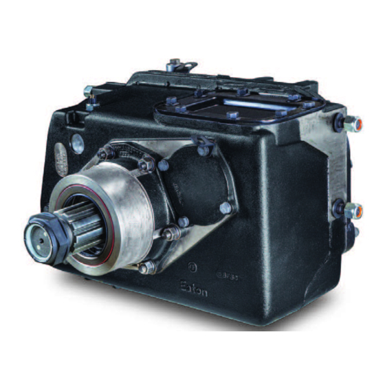
- Page 1 Service Manual Eaton Fuller Heavy-Duty Transmissions TRSM0996 EN-US April 2019 AT-1202 Models...
- Page 2 The description and specifications contained in this service publication are current at the time of printing. Eaton Corporation reserves the right to discontinue or modify its models and/or procedures and to change specifications at any time without notice.
- Page 3 Introduction Description The AT-1202 model is a two-speed, twin countershaft auxiliary transmission designed primarily for use with heavy-duty transmis- sions. This auxiliary transmission contains two sets of gears, thus giving the reduction (low) ratio when power is delivered through these two sets of gears.
- Page 4 Specifications Shift Positions and Specifications Shift Positions Nuetral Direct Reduction Specifications Gear Ratios Gear Ratios Direct 1.00 Reduction 2.036 Mountings Front bearing cover machined for trunnion mounting. Four 5/8" diameter mounting studs, two on each side of case. Power Take-OFF Bottom SAE Standard 6-bolt, 30 tooth, 5P gear on left coun- tershaft turning at .993 input shaft speed.
- Page 5 Lubrication Specifications Note: For a list of Eaton Approved Synthetic Lubricants, see TCMT-0021 the list of approved lubricants and TCMT-0021 the list of lube intervals, or call 1-800-826-HELP (4357). Recommended lubricants for the 2-A-92 are currently the E500 and the E250, which list a mileage, a year, and a hour change interval.
- Page 6 Maintenance Preventative Maintenance Check List The following maintenance checks can be made without removing the transmission from the chassis. Items 1 through 5 can be performed without any prior mechanical work; items 6 through 8 require the dropping of the output driveline and the input drive- line where possible.
- Page 7 Used to install the countershaft bearings. Specialty Tool Manufacturers Below are the addresses and phone numbers of the companies that make tools specifically for Eaton®Fuller® transmissions: G and W Tool Company 1105 E. Louisville, Broken Arrow, OK 74012-5724, Phone: 800-247-5882, or 918-258-6881...
- Page 8 Torque Torque Ratings Recommended torque ratings, location and thread sizes of capscrews and nuts are listed below. Capscrew lengths are given for reference purposes as a guide for installation at proper locations. Correct torque application is extremely important to assure long transmission life and dependable performance. Over-tightening or undertightening can result in a loose installation and in many instances, cause damage to transmission gears, shafts and bear- ings.
- Page 9 Removal and Disassembly General Instructions for Disassembly Important: Read this section before starting the detailed disassembly procedures. It is assumed in the detailed disassembly instructions that the transmission has been removed from the chassis, the lubricant has been drained, the parking brake removed, if so equipped, and both universal joint companion flanges have been removed. Follow each procedure closely in each section, making use of both the text and pictures.
- Page 10 Removal and Disassembly How to Remove the Companion Flanges or Yokes Special Instructions None Special Tools • Typical service tools Procedure - Brace against the yoke or flange on each shaft and use a large breaker bar to remove the elastic stop nut from each shaft.
- Page 11 Removal and Disassembly How to Remove the Rear Plate from the Front Case Special Instructions None Special Tools • Typical service tools Procedure - Loosen the jam nut and turn the rod end from the end of the shift bar. Turn out the 19 capscrews attaching the rear plate to the front case.
- Page 12 Removal and Disassembly Insert three puller screws in the three tapped holes in the mounting flange of the rear approximately 1/2 to break the gasket. Attach a chain hoist to the rear plate and move the plate evenly to the rear and off the front case dowel pins. Mount the rear plate in a vise in the upright position.
- Page 13 Removal and Disassembly How to Remove the Shifting Control Assembly With Air Special Instructions None Special Tools • Typical service tools 1. O-ring 11. Capscrew 2. Shift Cylinder 12. Shift Yoke 3. Shift Piston Assembly 13. Lockscrew 4. O-ring 14. Gasket 5.
- Page 14 Removal and Disassembly Procedure - Cut the lockwire and remove the yoke lockscrew. Remove the spacer from the front of the shift bar. Put a rag over the bore in the shift bar housing to prevent loss of the tension spring and ball and pull the shift bar sharply forward and from the housing.
- Page 15 Removal and Disassembly Remove the yoke from the sliding clutch and remove the sliding clutch from the splines of the output shaft. Turn out the four capscrews attaching the shift bar housing to the rear plate and remove the housing.l Tip the housing to remove the tension spring and ball.
- Page 16 Removal and Disassembly How to Remove the Shifting Control Assembly Without Air Special Instructions None Special Tools • Typical service tools 10 10 13 13 11 11 12 12 1. Eye Rod end 9. Plug 2. Nut 10. Capscrew 3. Yoke Bar 11.
- Page 17 Removal and Disassembly Procedure - Cut the lockwire and remove the yoke lockscrew. Remove the spacer from the front of the shift bar. Put a rag over the bore in the shift bar housing to prevent loss of the tension spring and ball and pull the shift bar sharply forward and from the housing.
- Page 18 Removal and Disassembly Turn out the four capscrews attaching the shift bar housing to the rear plate and remove the housing.l Tip the housing to remove the tension spring and ball.
- Page 19 Removal and Disassembly How to Remove the Countershaft Assemblies Special Instructions None Special Tools • Typical service tools 1. Bearing 2. Welded Countershaft 3. Bearing 4. Snap Ring Procedure - Use a three-jaw puller or equivalent to remove the front bearing from each countershaft.
- Page 20 Removal and Disassembly Remove the two countershaft rear bearing covers. Remove the snap ring from the rear of each countershaft. Use a soft bar and maul to drive the countershaft assemblies forward and from the rear bearings.
- Page 21 Removal and Disassembly Use a soft bar to tap the bearings to the rear and from the rear plate bores.
- Page 22 Removal and Disassembly How to Remove the Output Shaft and Reduction Gear Assembly Special Instructions None Special Tools • Typical service tools 1. Sliding Clutch 2. Mainshaft 3. Reduction Gear 4. Bearing 5. Snap Ring 6. Washer 7. Nut Procedure - Use a soft bar and maul to drive the output shaft forward and from the rear bearing assembly.
- Page 23 Removal and Disassembly Remove the bearing inner spacer from the shaft. Remove the snap ring from the groove in the I.D. of the re- duction gear. Use a soft bar to tap the reduction gear from the output shaft. Using the inner race of the reduction gear bearing as a base, press the rear bearing front cone from the output shaft.
- Page 24 Removal and Disassembly How to Remove the Rear Bearing Assembly Special Instructions None Special Tools • Typical service tools Procedure - Turn out the six capscrews attaching the rear bearing hous- ing to the rear plate.
- Page 25 Removal and Disassembly Remove the rear bearing housing, rear bearing cone and speedometer drive gear or replacement spacer from the rear plate. Use a soft bar to tap the front bearing cup and outer spacer forward and from the rear plate bore. From inside the plate, tap the rear bearing cup to the rear and from the rear plate bore.
- Page 26 Removal and Disassembly How to Remove the Input Shaft and Drive Gear Assembly Special Instructions None Special Tools • Typical service tools Procedure - Remove the snap ring from the groove in the rear of the cou- pling shaft. Pull the drive gear to the rear and from the splines of the coupling shaft.
- Page 27 Removal and Disassembly Use a soft bar and maul to drive the input shaft to the rear and from the front bearing assembly. Remove the snap ring from the input shaft. Press the input shaft rear bearing from the shaft.
- Page 28 Removal and Disassembly Mount the input shaft in a vise with the threaded end down and use a Allen wrench to remove the Allen screw located in the hub of the coupling shaft. It will be necessary to turn the Allen wrench with a crescent or open end wrench.
- Page 29 Removal and Disassembly How to Remove the Front Bearing Housing Assembly Special Instructions None Special Tools • Typical service tools Procedure - Remove the six nuts attaching the housing to the front case and pull the housing from the studs.
- Page 30 Removal and Disassembly If necessary to remove the oil seal or front bearing If necessary, remove the shifting bar packing and packing retainer from the front shifting bar bore in the case and re- move the Welch plug from the rear shifting bar bore. If necessary, remove the pipe plug from the bore in the top of the case.
- Page 31 Removal and Disassembly How to Disassemble the Front Case Special Instructions None Special Tools • Typical service tools Procedure - For reassembly purposes, remove the two countershaft front bearing covers. Note: Remove PTO gear covers, filler and drain plugs, breather and miscellaneous items as necessary. Re- moval of the seal and scraper in the shift bar bore will most likely damage the parts and removal should not be attempted unless replacement of the parts if...
- Page 32 Assembly and Installation Inspection and General Instructions for Reassembly Before reassembling the transmission, the individual parts should be carefully checked to eliminate those damaged from previous service. This inspection procedure should be carefully followed to insure the maximum of wear life from the rebuilt unit. The cost of a new part is generally a small fraction of the total cost of downtime and labor, should the use of a questionable part make additional repairs necessary before the next regularly scheduled overhaul.
- Page 33 Assembly and Installation Washers • Check the surfaces of the washers. Washers scored or reduced in thickness should be replaced. Shifting Bar Assembly • Check the yoke for alignment and straighten if sprung. • Check the lockscrew in the yoke and tighten and rewire if found loose. •...
- Page 34 Assembly and Installation General Instructions for Reassembly Make sure the interior of the case and the other housings are clean. It is important that dirt be kept out of the transmission during reassembly. Dirt is abrasive and can damage polished surfaces of sleeves, bushings, and bearings. Use certain precautions, as listed below, during reassembly.
- Page 35 Assembly and Installation Universal Joint Companion Flanges • Make sure the companion flanges are pulled tightly into place with the retaining nuts. Failure to tighten the retaining nuts, or omission of parts between flanges and bearings will premit the shafts to move axially, with resultant damage to the pilot bearing, mainshaft, and drive gear.
- Page 36 Assembly and Installation How to Assemble the Input and Coupling Shaft Special Instructions Mount the input shaft in a vise with the threaded end down. Do not secure the input shaft in the vise by the threads. Special Tools • Typical service tools Procedure - Apply a drop of Grade AVV Loctite to the threads of the Allen...
- Page 37 Assembly and Installation How to Assemble the Front Bearing Housing Assembly Special Instructions None Special Tools • Typical service tools Procedure - Install the rear bearing on the input shaft against the shoul- der on the shaft. Note: Heating of the bearing will faciliate installation. Do not heat the bearing over 275 °F.
- Page 38 Assembly and Installation Install the front bearing retaining snap ring in the groove in the housing. Make sure that the snap is in the groove and not just against the shoulder in the housing bore. Use an oil seal driver to install the front oil seal. The side of the oil seal with the seam should face into the housing, and the front of the seal should be flush with the face of the housing.
- Page 39 Assembly and Installation From inside the case, start the input shaft assembly into the bearing housing bore with a soft bar. Use a soft bar and maul to drive the shaft forward until the rear bearing seats against the shoulder in the bore. Install the drive gear on the shaft with the clutching teeth facing towards the rear of the case.
- Page 40 Assembly and Installation How to Assemble the Output Shaft and Reduction Gear Special Instructions None Special Tools • Typical service tools Procedure - Install the reduction gear bearing in the hub of the reduction gear with snap ring in the bearing facing up. Use a bearing driver or tap carefully on the outer race of the bearing with a soft bar.
- Page 41 Assembly and Installation Place the output shaft on a bench with the threaded end up and install the reduction gear on the shaft with the clutching teeth of the gear facing down. Install the washer on the shaft and against the gear with the larger bevel on the ID of the washer facing down.
- Page 42 Assembly and Installation Install the bearing inner spacer on the shaft.
- Page 43 Assembly and Installation How to Install the Output Shaft and Rear Bearing Assembly Special Instructions None Special Tools • Typical service tools Procedure - Install the bearing front cup in the rear plate bore, taper fac- ing up. Place the bearing outer spacer on the front cup and tap even- ly into the rear plate bore.
- Page 44 Assembly and Installation Place the rear plate over the output shaft assembly. Note: If the rear cup lip moves away from the plate, hold the lip in position against the plate by bolting a counter- shaft bearing cover on the plate mounting surface so that an edge of the cover holds the lip of the bearing cup against the rear plate.
- Page 45 Assembly and Installation Install the rear bearing housing on the rear plate with the six retaining capscrews. The capscrew with the brass washer is installed in the capscrew bore intersecting the speedometer bore. Note: The rear bearing housing may be installed with the speedometer bore on either the left or right hand side of the plate.
- Page 46 Assembly and Installation How to Time and Install the Countershaft Assemblies Special Instructions None Special Tools • Typical service tools Procedure - Mark the tooth which is stamped with an "O" on the reduction gear of each countershaft. Place one of the countershaft assemblies in position inside the plate with the marked tooth meshed between two of the marked teeth on the reduction gear.
- Page 47 Assembly and Installation Use a soft bar to start the countershaft rear bearing on the shaft and in the case bore. Use a bearing driver and maul to comlete installation of the countershaft rear bearing. Repeat the procedure for installa- tion of the remaining countershaft.
- Page 48 Assembly and Installation How to Install the Shifting Controls Special Instructions None Special Tools • Typical service tools Procedure - Install the tension spring in the bore of the shift bar housing. Install the tension ball over the spring, and use a screwdriver or equivalent to hold the tension ball down and insert the end of the shift bar with the three notches into the housing until the neutral (middle) notch is over the tension spring and...
- Page 49 Assembly and Installation Install the sliding clutch gear on the output shaft and place the shift yoke in position with the long hub of the yoke facing the rear plate. Place ths shift housing and bar in position, passing the shift bar through the yoke hub.
- Page 50 Assembly and Installation Install the yoke lockscrew. Tighten and lockwire securely. Install the spacer on the shift bar and against the yoke with the bevel on the ID of the spacer facing the yoke. Secure the shift bar housing to the rear plate with the four retaining capscrews.
- Page 51 Assembly and Installation How to Install the Rear Plate Special Instructions None Special Tools • Typical service tools Procedure - Attach a chain hoist to the rear plate and move the plate evenly into the front case, first guiding the shift bar into the front case bore and then installing the rear plate bores on the front case dowel pins.
- Page 52 Assembly and Installation Use a soft bar to start the countershaft front bearings on the shafts and into the case bores. Use a bearing driver to com- plete installation. The beveled ID of each bearing faces into the case. Install the two countershaft front bearing covers.
- Page 53 Assembly and Installation How to Perform Final Installation of the Shifting Controls Special Instructions None Special Tools • Typical service tools Procedure - If previously removed, install the jam nut on the rod end and turn the rod end into the end of the shift bar. Set the rod end in the desired position and lock in place by tightening the jam nut against the shift bar.
- Page 54 Assembly and Installation How to Install the Companion Flange or Yoke Special Instructions None Special Tools • Typical service tools Procedure - Install the yoke or flange on the input shaft and install the washer and elastic stop nut on the threads of the input shaft. On units not equipped with a speedometer drive gear, install the spacer on the output shaft and in the rear bearing hous- ing.
- Page 55 Assembly and Installation Use the special tool to hold the yoke or flange in position and torque the elastic stop nut on each shaft to 450-500 lbs. ft. torque. Note: If a special tool is not available, the stop nuts may also be installed by putting the transmission in direct gear and bracing against one shaft while torquing the stop nut on the other shaft.
- Page 56 Copyright Eaton, 2019. Eaton hereby grant their customers, vendors, or distributors permission to freely copy, reproduce and/or distribute this document in printed format. It may be copied only in its entirety without any changes or modifications. THIS INFORMATION IS NOT INTENDED FOR SALE OR RESALE, AND THIS NOTICE MUST REMAIN ON ALL COPIES.
Need help?
Do you have a question about the Fuller AT-1202 and is the answer not in the manual?
Questions and answers