
Related Manuals for Graf AquaControl+


Summary of Contents for Graf AquaControl+
- Page 1 User information AquaControl+ Fill level measuring device and drinking water supply Item – No.: 351021 Otto Graf GmbH Carl- Zeiss- Str. 2-6 Tel.: +49 7641 5890 Kunststofferzeugnisse D 79 331 Teningen Fax: +49 7641 58950...
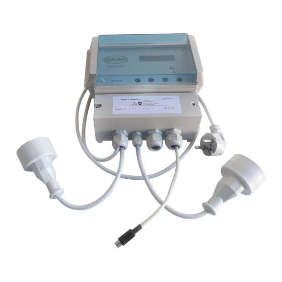
- Page 2 LED for power supply display 2: Display LED for drinking water operation LED for faults and malfunction Operating buttons Lower cover of the System Control Main connection cable with coupling for data lead and analogue outlet (0-10V) 8: Alarm indicator contact and valve connection for filter cleaning the rainwater filter 9: Valve connection with power coupling 10: The mains circuit breaker of the system controls are under this cover.
- Page 3 12: data cable 13: screw cap 3 14: Connection of the data cable is reverse protected. 15: connect white cable here 16: connect red cable here 17: data cable terminal 18: screw cap 2 19: screw cap 1 20: active measuring length 22: stainless steel weight 23: tank floor 24: Screws must be blunted ! (danger of injury)
- Page 4 Safety Insructions Please read carefully the safety and instruction manual before using this device! Follow all instructions that are in the User Guide (Manual) to achieve the optimal performance. Please keep these safety and operating instructions safe for further use. General Safety Instructions / Symbol Explanation - refers to an information - means warning and indicates a special situation...
-
Page 5: Electric Current
Limitation of the Liability The manufacturer would not take over any liability for damages resulting from: - the usage of the device by untrained and unauthorized personnel, - use of device for not intended purpose - opening and/or manipulation of the device - not following the manual and safety instructions Electric Current !!Danger of life from electric current!! -
Page 6: Power Supply
Power Supply The equipment may only be operated with the operating voltage of 230V AC specified in the user information. A residual current circuit breaker (RCD) with a rated residual current not greater than 30mA must be provided, because it is a socket outlet circuit which is intended for use by laypersons and for general use. -
Page 7: Opening The Device
1.11 Temperature and Heat The operating temperature of the device is defined in the specifications. The device must not be placed near things which produce heat such as to blowers, heaters, furnaces or other devices. 1.12 Opening the Device Disconnect the mains plug before opening the device! There is a risk of electrical shock when touching the parts inside the device. -
Page 8: Intended Use
1.16 Repairing The user is not allowed to perform the maintenance work by himself, except for those specified in the manual. All maintenance and repair work must be done by trained and au- thorized technical personnel. 1.17 Important notes of safety Please, read and follow safety instructions carefully before assembly or using the device! The mounting position must be suitable for a safe and secure routing and connecting of... - Page 9 Description The system controls offer an easy to use guide for the switch programming. Using an LCD display the fill measurement is shown in 1 % stages (in relation to the height of the tank).The sensor operates with a 12 volt supply. All programmed values such as the tank height are retained after disconnection of the power supply or after a power-cut.
-
Page 10: Control System
The yellow LED indicating “Drinking water operation”[3] is lit as soon as the valve switches over to the mains supply. The user is made aware that the system now uses water from the mains supply. The red LED for “Faults and malfunctions” [4] is lit as soon as the system identifies a fault. - Page 11 Now the sensor measurement pick-up [28] (cover removed) should be installed on the tank wall (preferably in the man hole shaft of the Graf synthetic tank). The location of the mounted sensor pick-up should be between 10 and 15 cm above the overflow [25].
-
Page 12: Electrical Wiring Diagram
Now pass the end of the data cable that has no plug connector [12] through the screw mounting 3 [13]. Lightly tighten the screw mounting and connect the cable wire cores of the data cable [12] to the double terminal [14]. The connection of the data cable is reverse polarity protected. - Page 13 Valve 230V AC Pressure AquaControl+ Pump (Net) switch Data cable ( 12V ) Sensor pick up element Sensor Picture 5: Electrical wiring diagram Should the existing pump or house water system already have a dry run protection it may be appropriate and is possible to order the AquaControl+ without a dry run protection.
- Page 14 The equipment type is shown on the first line and the software check in progress is shown in the second line. If after the initial installation check all is correct, the LCD indicator will display the fill level (in %). The figure 7 shows the LCD-display in the operation mode.
- Page 15 over and stored in the programming of the unit. Through pressing the “MENU” button again the display changes back to the operation mode. It is possible to reset the unit to the factory setting standard values at any time. The resetting can only be carried out in the operation mode (Display see Figure 7): To do this press the “OK”...
- Page 16 SWITCHING POINTS Main menu level key „OK“ PUMP ON Pump ON (The numerical value is always 0-100% smaller than with Valve ON.) Pump OFF (The numerical value is always PUMP smaller than with Pump ON.) 0-100% Supply with mains drinking water - ON (The VALVE ON numerical value is always smaller than with 0-100%...
- Page 17 The following is an introduction to the general device settings: Main menu level DEVICE ADJUSTMENT key „OK“ LANGUAGE ENGLISH MEASURING LENGHT [20] in Figure 2 30-600cm (A 6m Sensor may be ordered.) Picture 11: Sub-menu “General device description” The last part of the operation level covers the manual functions: MANUAL OPERATION Main menu level key „OK“...
-
Page 18: Error Messages And Fault Correction
Error messages and fault correction The operation of the system control is to be checked at regular intervals (at the latest every 4 weeks). The read out reports always represent only probabilities; e.g. no clear localization by the device is possible for overlaying faults. Please also take note that the system control device cannot identify any malfunction of the house water system. - Page 19 First try re-setting the system control to the ERROR factory default settings . If the error MEMORY message continues to be displayed then it is necessary to contact your service partner. Note: After re-setting to the factory default settings all the newly programmed setting values will have been overwritten and must be re-programmed!
-
Page 20: Upgrade Options
Upgrade options The AQ+ control device can also be equipped with a number of additional special func- tions. 1. Optional pressure sensor Using a pressure sensor, alternative mediums or depths may be adapted to the use of the device. The sensor must be matched the required specifica tions of the device. - Page 21 Analogue outlet Before opening the equipment pull the plug out from the mains socket! Your device has been fitted with an additional analogue port. This port shows the percent values from the system control (0% -100%) by a voltage range from 0V to 10V. The follow- ing connection values apply: Minimal apparent ohmic resistance : 20KΩ...
- Page 22 10. Alarm indicator contact Before opening the equipment pull the plug out from the mains socket! As an additional function, your unit is equipted with a potential-free alarm indicator contact. This contact is designed as a changeover contact element. A maximum of 230V AC is ap- proved when a current of 1A is switched.
- Page 23 11. General installation and assembly regulations It is necessary to these instructions when installing a rain water usage equipment: EN 806: - Drinking water installation - Planning and implementation - Calculation of the pipe diameters - Using the equipment EN 1717: - Free outlet between drinking and rainwater - Notification sign to inform that a rainwater usage system is in stalled in the locality...
-
Page 24: Disposal Of The Equipment
12. Disposal of the equipment Old equipment may not be disposed of in the house refuse. It must be brought to the recognised professional recycling depot. Please help – ensure your old electronics come to a separate recycling. 13. Manufacturer Should you have any problems with the equipment, please contact: GmbH Niederlassung Prenzlau... - Page 25 Attachment A – Symbols used: Attention! Pull out the mains plug from the socket before opening the device. Warning of dangerous electrical voltage Attention! An error has occurred. Mains drinking water operation Page down Page up Pump connection Valve connection Main connection for data lead Protection classification I Only for use in a dry areas.
- Page 26 Attachment B - Connection of the filter flush valve: Before opening the equipment pull the plug out from the mains socket! Connect the filter flush valve to the connections “3” and “5”. An existing protective conductor connection must be integrated into the protective conductor system. Connect the protective conductor to the “PE”...
- Page 27 Space for your notes:...
- Page 28 Revision history: Revision Date Description Author AQX 3.4 07.02.2018 Formatting A5 AQX 3.5 27.01.2020 Formatting A4 AQX 3.6 07.09.2020 Use of an RCD required Purchase date ........Device serial number / Type AS AQ ..... Design and specifications are subject to change without notice. Dated: September 2020 man_AQX_3-6_eng.odt...
Need help?
Do you have a question about the AquaControl+ and is the answer not in the manual?
Questions and answers