
Related Manuals for Graf AquaControl +


Summary of Contents for Graf AquaControl +
- Page 1 User information AquaControl + Fill level measuring device and drinking water supply Item no.: 351021 Otto Graf GmbH Carl-Zeiss-Str. 2-6 Tel .: 07641-5890 Kunststofferzeugnisse D-79 331 Teningen Fax: 07641-58950 Page 1...
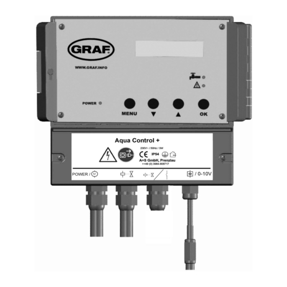
- Page 2 Figure 1: View of equipment LED for power supply display Display LED for drinking water operation LED for faults and malfunction Operating buttons Lower cover of the System Control Main connection cable with coupling for data lead and analogue outlet (0-10V) Alarm indicator contact and valve connection for filter cleaning the rainwater filter Valve connection with power coupling...
- Page 3 Figure 2: Sensor assembly Data cable screw cap 3 Connection of the data cable is reverse protected. connect white cable here connect red cable here data cable terminal screw cap 2 screw cap 1 Page 3...
- Page 4 active measuring length Stainless steel probe Tank floor Screws must be blunted ! (danger of injury) overflow Tank side in dome Sensor Sensor control box ( measurement pick-up ) 1. Safety Instructions Please read carefully the safety and instruction manual before using this device! Follow all instructions that are in the User Guide (Manual) to achieve the optimal performance.
- Page 5 1.2 Proper Use of the Device The equipment is designed exclusively for the intended purpose specified in the manual. Any other use and / or misuse of the device can lead to unpre- dictable risks including death and causes the loss of all the claims against the manufacturer.
- Page 6 1.7 Power Supply The equipment exclusively operates with the operating voltage indicated in the manual. 1.8 Cable Connection When installing the cable connections, the user needs to pay attention to the safety regulations. Always pay attention to the connection to the protective earth ground! Pay attention when connecting with other devices, that those have to be of the same earth potential (same heavy current/voltage side).
- Page 7 1.13 Cleaning Do not use any volatile solvents such as alcohol, diluents, gasoline etc. to clean the device. Only use a dry, clean cloth. 1.14 Unusual Smell If any unusual smoke or smell occurs, immediately switch off of the device and remove it from the main power supply! Contact your dealer or the manufacturer.
- Page 8 Power supply cables and data cables may not be damaged or squeezed for any reasons. Plan the assembly place so that you can reach the mains plug easily and unplug it from the electrical outlet in dangerous situations. Choose the assembly place so that children cannot play or be near to the device and at its connections without supervision.
- Page 9 Technical data: Control electronics Measurement sensors Operating current :230V AC Measurement voltage :12V DC Fused :T50mA Measuring frequency :(0,2-20)kHz Power consumption :3VA Data cable length :20m Tank height :3m (optional 6m) Measurements [mm] :155x165x90 Measurements [mm] :90x80x50 Pump connection Valve connections Operating voltage :230V AC Operating voltage...
- Page 10 Figure 4: Sensor technology 1. Now the sensor measurement pick-up [28] (cover removed) should be installed on the tank wall (preferably in the man hole shaft of the Graf synthetic tank). The location of the mounted sensor pick-up should be between 10 and 15 cm above the overflow [25].
- Page 11 tighten this lightly, then connect the red cable to the terminal [16]. The free white cable is now passed through the screw mounting 2 [18] and tightened lightly, then connect the white cable to the terminal [15]. 5. Now pass the end of the data cable that has no plug connector [12] through the screw mounting 3 [13].
- Page 12 4.3. Electrical wiring diagram The AquaControl+ offers the rain water system a dry run protection for the pump or the house water system. So that the dry run protection will function properly the rain water system must be wired according to the following diagram. Valve 230V AC Pressure...
- Page 13 Now open the transparent cover of the system controls. Plug the equipment into the mains socket (this socket must be exclusively for the equipment and be on its own fuse). The system then runs a system check through automatically. For the duration of the system check (approx. 10 seconds) the following signal will be displayed in the window: AQ + REV 3.1...
-
Page 14: Default Values
6. Set up of the system control: After putting into operation, the system control must be adjusted and programmed according to the conditions and requirements of the individual users system. The required settings are easily programmed. There are four buttons for this purpose. All necessary programming data entries follow a menu displayed by the LCD. - Page 15 TANK: FV- P+ key „MENU“ (>5s) SWITCHING POINTS MANUAL OPERATION DEVICE ADJUSTMENT Figure 9: Main menu level Press the “ENTER” button to arrive at each of the listed sub-menu functions. Through pressing the “MENU” button again the display changes back to the opera- tion mode.
- Page 16 + / - Flush the drinking water supply pipes for 30 DW DURATION seconds. 0-60 SEC + / - CLEANER INTERVAL Cleaning the rainwater filter every 14 days 0-14 DAYS The value 0 switches the cleaning process off. + / - Cleaning the rainwater filter for 5 seconds CLEANER DURATION 0-60 SEC...
- Page 17 Main menu level DEVICE ADJUSTMENT key „ENTER“ LANGUAGE ENGLISH + / - MEASURING LENGHT [20] in Figure 2 30-600cm (A 6m Sensor may be ordered.) + / - Figure 11: Sub-menu “General device description” The last part of the operation level covers the manual functions: MANUAL OPERATION Main menu level key „ENTER“...
- Page 18 7. Error messages and fault correction: The operation of the system control is to be checked at regular intervals (at the latest every 4 weeks). The read out reports always represent only probabilities; e.g. no clear localization by the device is possible for overlaying faults. Please also take note that the system control device cannot identify any malfunction of the house water system.
- Page 19 The communication between the system ERROR control to the measurement pick-up is SIGNAL interrupted. First try re-setting the system control to the ERROR factory default settings . If the error message MEMORY continues to be displayed then it is necessary to contact your service partner.
- Page 20 Please have the serial number of the device ready when you contact us! The serial No. is to be found on the Serial number plate on the lower cover of the system con- trol. 8. Upgrade options: The SILENTIO control device can also be equipped with a number of additional special functions.
- Page 21 9. Analogue outlet: Before opening the equipment pull the plug out from the mains socket! Your device has been fitted with an additional analogue pot. This port shows the percent values from the system control (0% -100%) by a voltage range from 0V to 10V.
- Page 22 10. Alarm indicator contact: As an additional function, your unit is equipted with a potential-free alarm indicator contact. This contact is designed as a changeover contact element. A maximum of 230V AC is approved when a current of 1A is switched. The activation of this con- tact occurs as soon as one of the malfunctions listed under point 6 appears.
- Page 23 11. Disposal of the equipment: Old equipment may not be disposed of in the house refuse. It must be brought to the recognised professional recycling depot. Please help – ensure your old electronics come to a separate recycling. 12. General installation and assembly regulations: It is necessary to these instructions when installing a rain water usage equipment: EN 806: Drinking water installation...
- Page 24 Technical regulations in relation to groundwater drainage according to EN 752 Drainage systems outside of buildings according to the regulations of the local services authorities When required: Obligatory registration of the system and other man- datory stipulations Page 24...
- Page 25 Attachment A – Symbols used: Attention! Pull out the mains plug from the socket before opening the device. Warning of dangerous electrical voltage Attention! An error has occurred. Mains drinking water operation Page down Page up Pump connection Valve connection Main connection for data lead Page 25...
- Page 26 Protection classification I Only for use in a dry areas. Alarm indicator contact and valve connection for cleaning the rainwater filter Revision history: Revision Date Description Author AQX3.4 07.02.18 Formatting Page 26...
- Page 27 Attachment B – connection for cleaning the rainwater filter Before opening the equipment pull the plug out from the mains socket! Page 27...
- Page 28 Room for your notes: Purchase date : ........Device serial number / Type : AS AQ ....... Active measuring length : ........Software level AQ+ REV : ..Design and specifications are subject to change without notice Dated: February 2018 ; Version: AQX 3.4 man_AQX_3-4_eng.odt Page 28...
Need help?
Do you have a question about the AquaControl + and is the answer not in the manual?
Questions and answers