
Related Manuals for Getinge FD1800


Summary of Contents for Getinge FD1800
- Page 1 GETINGE FD1800 TECHNICAL MANUAL 503712400 Service code 9817 Service code 9817 Always with you...
- Page 2 Page 2 av 64...
-
Page 3: Table Of Contents
Contents PREFACE _______________________________________________4 SAFETY REGULATIONS _________________________________5 General safety regulations ___________________________________ 5 In an emergency ___________________________________________ 5 Product liability ____________________________________________ 5 Isolator switch _____________________________________________ 5 INTRODUCTION ________________________________________6 Intended use of the machine _________________________________ 6 Attention symbols __________________________________________ 6 RCD ______________________________________________________ 6 Description _____________________________________________7 General ___________________________________________________ 7 Function __________________________________________________ 7... -
Page 4: Preface
• Technical manual (this manual) • Spare parts list Getinge reserves the right to change the specification and design without prior notice. The information in this manual was up to date on the date of issue of the manual. © Copyright The content of this manual must not be copied, in whole or in part, without the written consent of Getinge. -
Page 5: Safety Regulations
• Close shutoff valves in the water and (where present) steam supply lines. Product liability Any modification or incorrect use of the equipment without the approval of Getinge Disinfection AB invalidates Getinge Disinfection AB’s product liability. This product was manufactured by:... -
Page 6: Introduction
To meet the requirements of EN ISO 15883, the items must be placed in the proper holder, recommended by Getinge Disinfection AB. The customer is responsible for ensuring that an Installation Qualification and a Performance Qualification according to ISO 15883 are carried out before the product is put into use. -
Page 7: Description
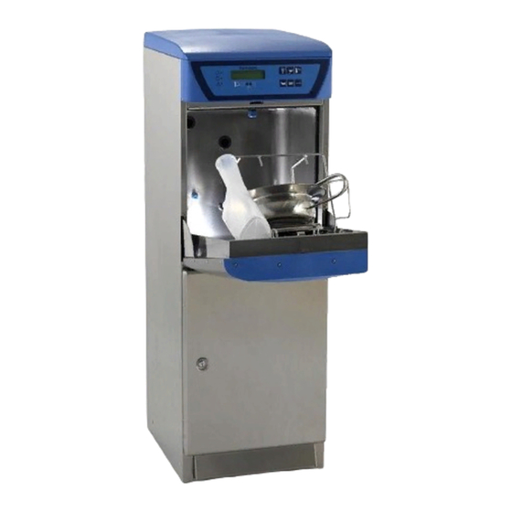
Description General The flusher disinfector is designed for cleaning and disinfecting circulation items such as bedpans and urine bottles. In this context, disinfection means killing all vegetative bacteria, fungal spores and viruses, but not bacterial spores. A description of the mechanical design and general functions of the machine is given the instruction manual. -
Page 8: P&I Diagram
P&I diagram G 1/2" G 1/2" B01A B01B B01C TIA/TIR Ø110 or 90mm. =OPTIONS Instrument funktioner enl. ISO 3511. Komponent märkning enl. IEC 750. Instrument functions acc. to. ISO 3511. Component marking acc. to IEC 750. Replace E01 and B20. Page 8 av 64... -
Page 9: Cooling
Safe and simple Disinfection is fully automatic • safety and reliability can be kept high by continuous monitoring of the process. • the dosing of descaler, the temperature and the disinfection time can all be altered with great precision to suit different conditions. •... - Page 10 The programs Programs, standard set: P1 Economy program for lightly soiled items. P2 Normal program for normally soiled items. P3 Intensive program for heavily soiled goods. The following programs can also be selected: P4 Normal program with detergent dosing (option). P5 Intensive program with detergent dosing (option).
-
Page 11: Service Program
Service program Function In the service program, maintenance and service personnel can set parameters which control the operation of the machine. These parameters are divided into the following groups: • Machine-independent settings • Configuration • Program selection • Interval disinfection •... - Page 12 Line Sub-line Parameter Basic setting Setting range Authorization Program selection, button 1 00-25 Program selection, button 2 00-25 Program selection, buttons 2+5 00-25 Program selection, button 3 00-25 Program selection, buttons 3+5 00-25 Program selection, button 4 00-25 The table on the pages that follow lists all the line and sub-line numbers of the machine. This section also describes how to work with the service program.
-
Page 13: Table Of Line Numbers And Line Information
Lines 00-09: Machine-independent variables Authorization code 0000-9999 ABCD Checking and retrieving settings 1=Basic, 2=Factory, 3=Work Machine type FD1800, etc. Program version (main version) 00.=00-99 Program version (sub-version) .00=00-99 Program version (test version) 00-99 Program protocol Serial number 0-999999... - Page 14 Line Sub- Parameter Basic Setting range Authorization line setting Line 30: Program selection Program selection button 1 00=No program, 01-20 Program no. CD Program name button 1 Economy program Program selection button 2 00=No program, 01-20 Program no. CD Program name button 2 Normal program Program selection buttons 2+5 00=No program, 01-20 Program no.
- Page 15 Line Sub- Parameter Basic Setting range Authorization line setting Line 34: Empty container alarm Alarm descaling agent 0125 00=no alarm, 01.99=warning, no. of programs after low level, 02=stop 01.01 Alarm descaling agent 0-99 processes remaining Alarm chemical agent 0200 00=no alarm, 01.99=warning, no.
- Page 16 Line Sub- Parameter Basic Setting range Authorization line setting Lines no 50-57: Tank and water Tank level at rest 1=Empty tank, 2=Level B, 3= Level C Water type, filling at rest 1 = cold, 2 = hot, 3 = cold and hot Mix ratio 0-100 % cold water Type of rim flushing...
- Page 17 Line Sub- Parameter Basic Setting range Authorization line setting Row 96: Activation inputs Activation, level A 0=input not active, 1=input active Activation, level B 0=input not active, 1=input active Activation, level C 0=input not active, 1=input active Activation, descaler, low level 0=input not active, 1=input active Activation descaler empty 0=input not active, 1=input active...
- Page 18 Line Sub- Parameter Basic Setting range Authoriza- line setting tion Line 98: Input connections Connection, level A 1-99 Connection, level B 1-99 Connection, level C 1-99 Conn., descaler, low level 1-99 Conn., descaler, empty 1-99 Connection chemical agent low level 1-99 Connection chemical agent empty 1-99...
-
Page 19: The Service Program
The service program NOTE: You must enter your authorization code before you can change anything in the programming; see under Authorization code. If the reading is flashing it can be changed. If it is not flashing, either it cannot be changed or you do not have the authority to change it. - Page 20 Check or change a numerical value on a line without a sub-line number • Press (increase line number) or (reduce line number) so the display shows the right line number. Holding down the button scrolls the value up or down for as long as the button is pressed.
- Page 21 Check or change a numerical value on a line with a sub-line number • Press (increase line number) or (reduce line number) so the display shows the correct line number. Holding down the button scrolls the value up or down for as long as the button is pressed.
-
Page 22: Machine-Independent Variables, Lines 00-09
Machine type Line 2 Shows the machine type to which the program applies. 1000 = Low spec (SP1000) 2000 = High spec (Getinge 2000) This value cannot be changed. Program version Line 3, sub-lines 01-04 Shows the program version of the chips on the computer board. - Page 23 Language. Line 5 Authorization level: CD Shows which language appears on the display when the machine is running. The following languages are available: 01 = German 02 = Swedish 03 = English 04 = French 05 = Italian 06 = Dutch 07 = Danish 08 = Hungarian 09 = Spanish...
- Page 24 Dosing method Line 13:1 Authorization level: BCD With the function in Manual mode: You must press before starting the program to ensure that cleaning agent is added during the program. With the function in Automatic mode: Detergent is added automatically during each program. Press if you do not want to add detergent during the program.
- Page 25 Mains frequency Line 19 Authorization level: CD Adaptation to the frequency of the electricity supply network. 1 = 50 Hz 2 = 60 Hz Pump starting time Line 20 Authorization level: CD Setting always 0.0 Temperature indication (red LED) Line 21 Authorization level: CD Choose between two functions for the red LED on the panel: 01 = The LED is lit if the disinfection temperature has not been reached during the...
- Page 26 Program selection and program name Line number 30, Sub-line numbers 11 - 62 Authorization level: CD Function for determining which program is to be linked to the program selection buttons. In the standard version, the following six programs, among others, may be linked to any chosen button: The numbers of the programs are as follows.
- Page 27 Contact Getinge Disinfection for further information about these programs. Each sub- line number corresponds to a button or a combination of buttons. Choose programs and program names for the buttons, based on the equipment of the machine. The sub-line numbers are as follows: 11 = Program selection button (normally programmed 1.
-
Page 28: Interval Disinfection, Line 31
Interval disinfection, line 31 Interval disinfection active Line 31, sub-line 01 Authorization level: CD Here you can activate or deactivate the interval disinfection function. 00 = Not active 01 = Active Interval disinfection programs Line 31, sub-line 02 Authorization level: CD Choose the program to be run on interval disinfection. -
Page 29: Inspection Request, Line 32
Inspection request, line 32 This function is used to get a continuous maintenance service of the machine. When the function is active, a message stating that an inspection is due appears on the display after a certain number of hours or program runs. Processing of inspection requests Line 32, sub-line 01 Authorization level: CD... -
Page 30: Dosage, Line 33
Dosage, line 33 Line 33, sub-lines 01 - 04 Authorization level: BCD Here you can set the dosing time for the various agents used during a process. The various sub-lines correspond to the following agents: Sub-line 01 Dosing time, descaler. 0 - 99 seconds in one-second steps. - Page 31 Standby disinfection method Line 36 Authorization level: CD There is a choice of four disinfection methods: 01 = D-T-D, Decentral-Thermal-Disinfection 02 = C-T-D, Central-Thermal-Disinfection 03 = D-C-D, Decentral-Chemical-Disinfection) Lower disinfection temperature Line 38 Authorization level: CD The heating is switched on at this temperature. Upper disinfection temperature Line 39 Authorization level: CD...
-
Page 32: Tank And Water, Lines 50 - 55
Handling auto-disinfection Line 45 Authority level: CDE This selection determines how auto-disinfection is handled. 01 = Selection of how to handle auto-disinfection 02 = What is the earliest time that auto-disinfection should begin 03 = What is the latest time that auto-disinfection should begin Dosage, chemical agent Line 48 Authorization level: CD... - Page 33 Type of rim flushing Line 53:01 Authorization level: CD Specify whether rim flushing will take place. 00 = No rim flushing 01 = Rim flushing in the machine Addition of softened water Line 54 Authorization level: CD Specify whether soft water is to be added and if so where. The time for which the water will be added is specified at line 55.
-
Page 34: Fault Statistics, Lines 60 - 63
Fault statistics, lines 60 - 63 Time of fault Line 60 Shows the number of seconds for which the program had been running when the fault occurred. 00 - 9999 seconds This value cannot be changed. Instruction for last fault Line 61 Show the program line in the relevant program where the fault occurred. -
Page 35: Program Statistics, Lines 70 - 74
Program statistics, lines 70 - 74 Max disinfection temperature Line 70 Highest temperature reached in the last program that was run. 80 °C to 99 °C This value cannot be changed. Program time, last program Line 71 Program time in for the last program to be run. 00 - 9999 seconds This value cannot be changed. -
Page 36: Function Test, Lines 80 - 83
Function test, lines 80 - 83 Display test Line 80 Authorization level: CD Press ENTER. All LEDs light up and all segments on the display flash. The LEDs and the display return automatically normal after a short time. Reading inputs 1 - 14 Line 81, sub-lines 00 - 14 Authorization level: CD All digital inputs can be read. - Page 37 Control, outputs 1 - 12 Line 82, sub-lines 1 - 12 Authorization level: CD Note: For certain outputs to be activated, the door must be closed and locked. All digital outputs can be controlled. The sub-line number corresponds to the number of the output, as follows (connection: line 99, activation: line 97): Output Function...
- Page 38 Activation, inputs Line number 96, Sub-line numbers 01 - 17 Authority level: CDE This line number is used to tell the software which logical inputs are installed. Some sub-line numbers are not included. They are reserved for future use. For each input, specify: 00 = input not installed 01 = input installed The sub-line numbers correspond to the following inputs:...
- Page 39 Activation, outputs Line 97, sub-lines 01 - 20 Authorization level: CD This line number is used to tell the software which logical outputs are installed. Some sub-line numbers are not included. They are reserved for future use. For each output, specify: 00 = output not installed 01 = output installed The sub-line numbers correspond to the following outputs:...
- Page 40 Input connections Line 98, sub-lines 01 - 17 Authorization level: D This line number is used to tell the software which physical inputs are connected to each logical input. Some sub-line numbers are not included. They are reserved for future use. The sub-line numbers correspond to the following logical inputs: The “Physical inputs”...
- Page 41 Output connections Line 99, sub-lines 01 - 20 Authorization level: D This line number is used to tell the software which physical outputs are connected to each logical output. The sub-line numbers correspond to the following logical outputs: The “Physical output” column shows the connections set at the factory: Sub-line No Function Physical output...
-
Page 42: Fault Indications
Fault indications Fault message For certain faults in the process, information about the cause of the fault is given on the display on the front panel. The fault messages must be acknowledged when the fault has been put right. For further information see under “Acknowledging a fault message.” The following fault messages may appear: Fault codes (must be acknowledged): Fault code... -
Page 43: Acknowledging A Fault Message
Acknowledging a fault message This must only be done by authorized personnel. Some messages need to be acknowledged before the machine can be returned to run mode. When the cause of the fault has been found and the fault has been put right, the fault message is acknowledged as follows: First press the button, then the... -
Page 44: Table Of Faults And Possible Actions
Table of faults and possible actions This must only be done by authorized personnel. The machine is connected to the electricity supply and some components are live Error Possible cause / Action The display is black Check the circuit breaker The electronics unit is not working. -
Page 45: Preventive Maintenance
PREVENTIVE MAINTENANCE The required maintenance intervals depend largely on the quality of the incoming water and how often the machine is used. The maintenance interval will have to be determined in each individual case. We recommend that the stated maintenance operations are done once or twice a year. - Page 46 Activity / Component Interval Inspection / Replacement Every Every Time year other year required Process tank Clean as needed (page 54) • 15 min Check the level indicator function (page 54) • 5 min Check the function and any leakage in the valves. •...
-
Page 47: Function Check
Function check This must only be done by authorized personnel. The machine is connected to the electricity supply and some components are live. Instructions, cable, switch • Check that a goods placing sign and quick help instructions have been put up on the wall behind the disinfector. - Page 48 1 General Checking electrical cables and connection points The purpose of checking the cabling and connection points is primarily to avoid personal injury as well as damage to the machine itself. 1. Check that the power cord to the electrical unit is intact, free of errors and installed as per the instructions.
- Page 49 1.2 Checking the ventilation fan The purpose of checking the ventilation fans is to avoid excessively high temperatures developing in components during operation. 1. Check that the fan rotates and blows air. 2. Clean the fan blades if there is dirt on them. Checking the fan is necessary because abnormal temperatures can occur during operation.
- Page 50 Check the function of the check valves and clean as necessary. The check valves are important not just for the ventilation process. In addition to reduced ventilation, leakage can also occur. Clean the contact surfaces and replace broken parts as needed. Check hoses to ventilator for leakage/loose connections.
- Page 51 3.1.3. Replacing a jet nozzle This must only be done by authorized personnel. Flushing chamber Nozzle Jet nozzle V1356 • A lternative 1. Use a fixed wrench (size 10 mm) to lock the nut between the nozzle and the rotating nozzle. Then unscrew the nozzle by hand. V574 • A lternative 2. Hold the nozzle and unscrew the nozzle head.
- Page 52 3.2 Checking fixed nozzles This is inspected to prevent the nozzle from becoming clogged with dirt and deposits, etc. Failure to perform the inspection can result in poor cleaning results. Unscrew the nozzle from the chamber and clean it inside and out. Mount the nozzle back again.
- Page 53 3.5 Checking the door seal and chamber seal The inspection is done to check the seal on the door (the seal at the bottom edge of the door) and the chamber seal (the seal that runs along the front edge of the chamber). Failure to perform this inspection can result in unwanted leakage of water and steam.
- Page 54 4 Process tank 4.1 Process tank In order to maintain good hygiene and proper functioning, the process tank should be cleaned regularly. If this is not done, there is an increased risk of bacterial growth in the tank, which can cause hygiene problems.
- Page 55 5 Steam generator 5.1 Checking the steam generator Check the connections for the steam generator for leakage and that the insulation is in- tact so that no hot surfaces are exposed. 5.2 Checking the function of the steam generator 5.3 Cleaning the steam generator Cleaning the steam generator as needed This must only be done by authorized personnel.
- Page 56 Gasket Check valve Check valve Clamping ring O-ring J155 Ball valve Cover Insulation V1945 5.3.1 Overheat protection This must only be done by authorized personnel. The machine is connected to the electricity supply and some components are live. The steam generator has an overheat cutout which trips if the temperature in the steam generator becomes too high.
- Page 57 6 Circulation pump The main pump is a very important component for the machine to function. It has a direct impact on cleaning. If you suspect a problem or a reduction in function for this component, replace it immediately. 6.1 Checking the circulation pump Check the mounting for the pump so that it is secure and not making any noises during operation.
- Page 58 7.2.1 Setting dosages This must only be done by authorized personnel. The pumps in the various systems cannot be adjusted. All adjustments are done by varying the running time of the pump during the cleaning program. Adjustment is done in the service program. The machine may be fitted with the following dosing systems: Dosing system Default...
- Page 59 8 Drainage connection The drain removes contaminated water and any potential leakage will end up in the machine and out on the floor by the machine. Check the drain connections for leakage Seal/tighten the connections as needed. Replace any cracked or defective parts. 9 Automatic door (option) 9.1 Checking the automatic door •...
-
Page 60: Draining The Machine
Draining the machine If the machine will not be used for more than 72 hours, Getinge Disinfection recom- mends draining the steam generator and circulation pump. Draining the steam generator Unscrew the cover from the underside of the ball valve on the steam generator. Open the ball valve and drain the steam generator. -
Page 61: Opening The Door In The Event Of A Power Failure
Opening the door in the event of a power failure Remove the cover from the machine to access the locking mechanism. Push the locking mechanism to the side. Then open the door. Page 61 av 64... -
Page 62: Component List
-U01 -K03 -K04 Component list -X50 -F03 -A10 -K02 -M16 -A01 -F1,-F3 -S03 -M06 -S04 -F01 -S05 -B01 -Y01 -A11 -Y02 -B07 -M17 -B05* -M01 -E01 -Q01 -M03 -M04 -M07 -M18 -S11 -B02, -B04, -B06 -B05* -A01 Control system, processor board Fuse door lock board 200mAT -S03 Limit switch, door closed... - Page 63 Page 63 av 64...
- Page 64 Getinge Australia Pty Ltd France Singapore PO Box 50 Getinge France SAS Getinge International Far East Pte. Ltd. Bulimba QLD 4171 BP 49, avenue du Canada 20 Bendemeer Road, Australia ZA de Courtaboeuf #06-02, Cyberhub Building E-mail: info@getinge.com.au Les Ulis, FR-91942...
Need help?
Do you have a question about the FD1800 and is the answer not in the manual?
Questions and answers