Mitsubishi Electric 800 Series Instruction Manual
Plug-in option, analog output function, digital output function
Hide thumbs
Also See for 800 Series:
- Instruction manual (727 pages) ,
- Instruction manual (function (534 pages) ,
- Manual (183 pages)

Related Manuals for Mitsubishi Electric 800 Series


Summary of Contents for Mitsubishi Electric 800 Series
- Page 1 INVERTER PRE-OPERATION INSTRUCTIONS Plug-in option INSTALLATION FR-A8AY E KIT PARAMETER LIST INSTRUCTION MANUAL ANALOG OUTPUT DIGITAL OUTPUT Analog output function Digital output function...
-
Page 2: Safety Instructions
Safety instructions Thank you for choosing this Mitsubishi Electric inverter plug-in option. This Instruction Manual provides handling information and precautions for use of this product. Incorrect handling might cause an unexpected fault. Before using this product, read all relevant instruction manuals carefully to ensure proper use. - Page 3 Injury Prevention CAUTION The voltage applied to each terminal must be the ones specified in the Instruction Manual. Otherwise an explosion or damage. may occur. The cables must be connected to the correct terminals. Otherwise an explosion or damage may occur. ...
- Page 4 CAUTION Usage When parameter clear or all parameter clear is performed, the required parameters must be set again before starting operations. Because all parameters return to their initial values. Static electricity in your body must be discharged before you touch the product. Maintenance, inspection and parts replacement ...
-
Page 5: Table Of Contents
— CONTENTS — Safety instructions 1 PRE-OPERATION INSTRUCTIONS Unpacking and checking the product..........................7 1.1.1 Product confirmation ................................7 Component names ................................8 Specifications ..................................9 2 INSTALLATION Pre-installation instructions ............................10 Installation procedure ..............................10 Wiring....................................18 3 PARAMETER LIST 4 ANALOG OUTPUT Connection diagram ..............................24 Terminals..................................25 Extended analog output function parameter list ......................26 Adjustment procedure ..............................27... - Page 6 5 DIGITAL OUTPUT Terminals..................................35 Digital output function parameter list..........................36 Parameter setting ................................36 APPENDIX Appendix 1 Instructions for compliance with the EU Directives ..................38 Appendix 2 Instructions for EAC ............................39 Appendix 3 Restricted Use of Hazardous Substances in Electronic and Electrical Products ........40 Appendix 4 Referenced Standard (Requirement of Chinese standardized law) ............41 REVISIONS...
-
Page 7: Pre-Operation Instructions
PRE-OPERATION INSTRUCTIONS Unpacking and checking the product Take the plug-in option out of the package, check the product name, and confirm that the product is as you ordered and intact. This product is a plug-in option made for the FR-E800 series inverters. 1.1.1 Product confirmation Check the enclosed items. -
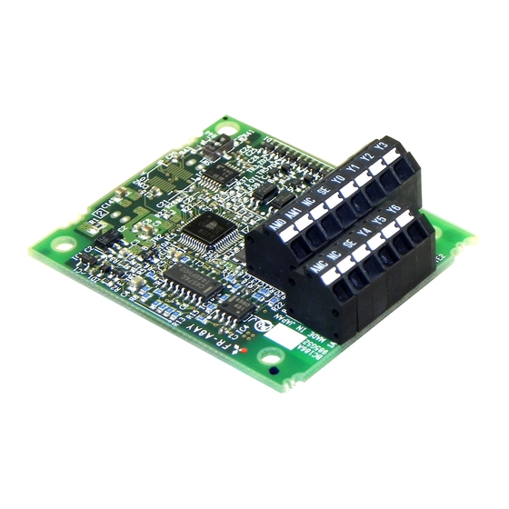
Page 8: Component Names
Component names Rear view Front view Refer to Symbol Name Description page Mounting hole Used to fix this product to the inverter by inserting a mounting screw or a spacer. Connects the device to input the signal to the inverter, and the device to receive Terminal block the signal from the inverter. -
Page 9: Specifications
Specifications Analog output Item Voltage output Current output Output signal 0 to ±10 VDC max (across terminals AM0 to AMC) 0 to 20 mADC (across terminals AM1 to AMC) Output resolution 3 mV 10 mA DC voltmeter DC ammeter Full-scale ±10 V (internal impedance: 10 kW or more) Full-scale 20 mA (internal impedance: 300 W or less) Applicable meter... -
Page 10: Installation
INSTALLATION Pre-installation instructions Check that the inverter's input power and the control circuit power are both OFF. CAUTION • Do not install or remove this product while the inverter power is ON. Doing so may damage the inverter or this product. •... - Page 11 For the FR-E820-0175(3.7K) or lower, FR-E840-0170(7.5K) or lower, and FR-E860-0120(7.5K) or lower Remove the inverter front cover. (Refer to the FR-E800 Instruction Manual (Connection) for instructions to remove the cover.) Use a nipper or the like to cut off the bottom of the front cover for plug-in option. Ensure no burr is left.
- Page 12 Install the hexagon spacers to the inverter. Fit the junction connector, which has been connected to the plug-in option, to the guide of the option connector on the inverter, and insert the junction connector as far as it goes. Fasten this product to the inverter using the two mounting screws through the holes on either side (tightening torque 0.33 to 0.40 N·m).
- Page 13 For the FR-E820-0240(5.5K) or higher Remove the upper front cover and the lower front cover from the inverter. (Refer to the FR-E800 Instruction Manual (Connection) for instructions to remove the covers.) Use a nipper or the like to cut off the dummy cover of the lower front cover in order to install the option small cover. Upper front cover Dummy cover Ensure no burr is left.
- Page 14 Install the hexagon spacers to the inverter. Fit the junction connector, which has been connected to the plug-in option, to the guide of the option connector on the inverter, and insert the junction connector as far as it goes. Fasten this product to the inverter using the two mounting screws through the holes on either side (tightening torque 0.33 to 0.40 N·m).
- Page 15 Install the lower front cover to the inverter. 6. Plug-in option 4. Hexagon spacer 7. Mounting screw 10. Front cover for plug-in option 4. Junction connector 9. Recessed neck screw 7. Mounting screw 4. Straight spacer 10. Option small cover 11.
- Page 16 Insertion positions for screws and spacers Mounting screw Straight spacer Connector L-shaped spacer Mounting screw Insertion positions for screws and spacers INSTALLATION...
- Page 17 NOTE • When the junction connector is installed to the plug-in option, the option is fixed with the hooks of the connector. The junction connector cannot be removed from the plug-in option. • When removing the front cover for plug-in option from the inverter, note that the recessed neck screw cannot be removed from the front cover for plug-in option.
-
Page 18: Wiring
Wiring For the wiring, strip off the sheath of a cable, and use it with a blade terminal. For a single wire, strip off the sheath of the wire and apply directly. Insert the blade terminal or the single wire into a socket of the terminal. Strip off the sheath as shown below. - Page 19 Blade terminals commercially available (as of December 2019. The product may be changed without notice.) Ferrule terminal model Cable gauge Crimping tool Manufacturer Without insulation name With insulation sleeve For UL wire sleeve AI 0,34-10TQ — — AI 0,5-10WH — AI 0,5-10WH-GB 0.75 AI 0,75-10GY...
- Page 20 Insert the cable into a socket. When using a single wire or stranded wires without a blade terminal, push the open/close button all the way down with a flathead screwdriver, and insert the wire. Open/close button Flathead screwdriver • Wire removal Pull the wire while pushing the open/close button all the way down firmly with a flathead screwdriver.
- Page 21 NOTE • When using stranded wires without a blade terminal, twist enough to avoid short circuit with a nearby terminals or wires. • Pulling out the wire forcefully without pushing the open/close button all the way down may damage the terminal block. •...
-
Page 22: Parameter List
PARAMETER LIST The following parameters are used for this plug-in option (FR-A8AY). Minimum Refer Initial Name Setting range setting group value increments page M303 Analog output signal selection M340 Setting for zero analog output 0 to 100% 0.1% M341 Setting for maximum analog output 0 to 100% 0.1% 100%... - Page 23 Minimum Refer Initial Name Setting range setting group value increments page M410 DO0 output selection M411 DO1 output selection M412 DO2 output selection M413 DO3 output selection Digital 9999 output M414 DO4 output selection later M415 DO5 output selection M416 DO6 output selection M432 Extension output terminal filter...
-
Page 24: Analog Output
ANALOG OUTPUT Connection diagram By setting Pr.306 to Pr.312, analog signals such as the output frequency and output current can be output from the voltage output terminal (AM0) and current output terminal (AM1). Connect the voltmeter or ammeter as shown below: MCCB Inverter Motor... -
Page 25: Terminals
Terminals Empty terminal. Do not use. Terminal Terminal name Description symbol Voltage output terminal Connects the DC voltmeter (±10 VDC). Current output terminal Connects the DC ammeter (20 mADC). Common terminal Common terminal for AM0 and AM1. Y0 to Y6 Used for digital output function. -
Page 26: Extended Analog Output Function Parameter List
Extended analog output function parameter list Parameter Minimum Initial Name Setting range number increments value Analog output signal selection Setting for zero analog output 0 to 100% 0.1% Setting for maximum analog output 0 to 100% 0.1% 100% Analog output signal voltage/current switchover 0, 1, 10, 11 Analog meter voltage output selection Setting for zero analog meter voltage output... -
Page 27: Adjustment Procedure
Adjustment procedure 4.4.1 Analog output signal voltage/current switchover (Pr.309) setting Use Pr.309 Analog output signal voltage/current switchover to select whether to send the same signal from terminal AM0 (voltage output) and terminal AM1 (current output), or to send the signals separately. Pr.309 Calibration Description... - Page 28 Pr.309 Calibration Description Terminal Parameter setting setting parameter value Pr.310: Selects the output signal. Pr.311: Output signal value when analog output is Pr.323 zero. C0 (Pr.900) Pr.312: Output signal value when analog output is at maximum. Pr.306: Selects the output signal. Pr.307: Output signal value when analog output is Pr.324 zero.
-
Page 29: Meter Calibration
4.4.2 Meter calibration Outputting the same signal from terminals AM0 and AM1 (Pr.309 = "0 or 10") START Connect a DC voltmeter (or DC ammeter) across At this time, check that the polarity is correct terminals AM0 (or terminal AM1) and AMC. If the meter needle does not point to 0 when voltage or current input is 0, Use Pr.323 (Pr.324) to calibrate the meter use Pr.323 AM0: 0 V adjustment or Pr.324 AM1: 0 mA adjustment to... - Page 30 Outputting separate signals from terminals AM0 and AM1 (Pr.309 = "1 or 11") START Connect a DC voltmeter (or DC ammeter) At this time, check that the polarity is correct across terminals AM0 (or terminal AM1) and AMC. Use Pr.323 (or Pr.324) to calibrate the meter If the meter needle does not point to 0 when voltage or current input is 0, use Pr.323 AM0 for 0 V adjustment or Pr.324 AM1 for 0 mA adjustment of when the voltage (current) input is 0.
-
Page 31: Setting Output Signals
4.4.3 Setting output signals Set the output signals to be monitored. Set Pr.306 to output the same signal from terminals AM0 and AM1, and Pr.306 and Pr.310 to output different signals. The AM0 terminal can be used for negative output (from -10 VDC to +10 VDC). The settings of Pr.306 and Pr.310 are the same as those of Pr.54 FM terminal function selection and Pr.158 AM terminal function selection. -
Page 32: Adjusting The Analog Signal (Pr.307, Pr.308, Pr.311, Pr.312)
4.4.4 Adjusting the analog signal (Pr.307, Pr.308, Pr.311, Pr.312) Use Pr.307 or Pr.311 to set the values at zero analog output (meter points 0) and Pr.308 or Pr.312 at maximum analog output (full scale). When outputting the same signal from terminals AM0 and AM1, use Pr.307 to set the value at zero analog output and Pr.308 at maximum analog output. - Page 33 Pr.309 = "10, 11" Pr.290 = "0, 1, 4, 5" (output without minus sign) Pr.290 = "8, 9, 12, 13" (output with minus sign) Analog output Analog output Limited at 10 V Limited at 10 V Current (AM1): 20 mA Voltage (AM0): 10 V Current (AM1): 20 mA Voltage (AM0): 10 V...
-
Page 34: Precautions
Precautions • When using a voltmeter with a lower internal impedance or an ammeter having a greater internal impedance than the value indicated in the specifications (Refer to page 9), the indicator may not go to full-scale, making it unable to calibrate in some cases. -
Page 35: Digital Output
DIGITAL OUTPUT Terminals Use Pr.313 to Pr.319 to output inverter signals (RUN, SU, etc.) as open collector outputs. Empty terminal. Do not use. Terminal Terminal name Description symbol Assigns the function using Pr.313. Assigns the function using Pr.314. Assigns the function using Pr.315. Digital output terminal Assigns the function using Pr.316. -
Page 36: Digital Output Function Parameter List
Digital output function parameter list Parameter number Name Initial value Setting range DO0 output selection 9999 DO1 output selection 9999 DO2 output selection 9999 DO3 output selection 9999 DO4 output selection 9999 DO5 output selection 9999 DO6 output selection 9999 Extension output terminal filter 9999 5 to 50 ms, 9999... - Page 37 Adjusting the output terminal response level (Pr.418) The response level of the output terminals can be delayed in a range of 5 to 50 ms. (Operation example for the RUN signal.) Time Pr.418 = 9999 Pr.418 ≠ 9999 Pr.418 Pr.418 NOTE •...
-
Page 38: Appendix
CE marking. • The authorized representative in the EU The authorized representative in the EU is shown below. Name: Mitsubishi Electric Europe B.V. Address: Mitsubishi-Electric-Platz 1, 40882 Ratingen, Germany EMC Directive We declare that this product conforms with the EMC Directive when installed in a compatible inverter, and affix the CE marking on the packaging plate. -
Page 39: Appendix 2 Instructions For Eac
Year, and the Month is indicated by 1 to 9, X (October), Y (November), or Z (December). • Authorized sales representative (importer) in the CU area The authorized sales representative (importer) in the CU area is shown below. Name: Mitsubishi Electric (Russia) LLC Address: 52, bld 1 Kosmodamianskaya Nab 115054, Moscow, Russia Phone: +7 (495) 721-2070... -
Page 40: Appendix 3 Restricted Use Of Hazardous Substances In Electronic And Electrical Products
Appendix 3 Restricted Use of Hazardous Substances in Electronic and Electrical Products The mark of restricted use of hazardous substances in electronic and electrical products is applied to the product as follows based on the “Management Methods for the Restriction of the Use of Hazardous Substances in Electrical and Electronic Products”... -
Page 41: Appendix 4 Referenced Standard (Requirement Of Chinese Standardized Law)
Appendix 4 Referenced Standard (Requirement of Chinese standardized law) This Product is designed and manufactured accordance with following Chinese standards. EMC: GB/T 12668.3 APPENDIX... - Page 42 MEMO IB(NA)-0600880ENG-A APPENDIX...
-
Page 43: Revisions
REVISIONS *The manual number is given on the bottom left of the back cover. Revision date *Manual number Revision Dec. 2019 IB(NA)-0600880ENG-A First edition... - Page 44 INVERTER HEAD OFFICE: TOKYO BUILDING 2-7-3, MARUNOUCHI, CHIYODA-KU, TOKYO 100-8310, JAPAN IB(NA)-0600880ENG-A(1912) MEE Printed in Japan Specifications subject to change without notice.
Need help?
Do you have a question about the 800 Series and is the answer not in the manual?
Questions and answers