Table of Contents
Advertisement
Quick Links
Advertisement
Chapters
Table of Contents

Related Manuals for Rohde & Schwarz R&S ZN-Z3x


Summary of Contents for Rohde & Schwarz R&S ZN-Z3x
- Page 1 ® R&S ZN-Z3x Inline Calibration System User Manual (;ÛÍß2) 1177.6381.02 ─ 03...
- Page 2 ® This manual describes the Inline Calibration System R&S ZN-Z3x, comprising the following components: ● R&S ® ZN-Z30 "Inline Calibration Controller", order no. 1328.7609.02 ● R&S ® ZN-Z32 "Inline Calibration Unit 8.5 GHz", order no. 1328.7638.02 ● R&S ® ZN-Z33 "Inline Calibration Unit 40 GHz", order no. 1328.7644.02 ●...
-
Page 3: Table Of Contents
® Contents R&S ZN-Z3x Contents 1 Introduction................5 2 Putting the System into Operation........9 3 Application................23 4 Operation................25 5 Maintenance................. 47 6 ZN-Z3x User Tool..............51 List of Commands............... 59 Index..................61 User Manual 1177.6381.02 ─ 03... - Page 4 ® Contents R&S ZN-Z3x User Manual 1177.6381.02 ─ 03...
-
Page 5: Introduction
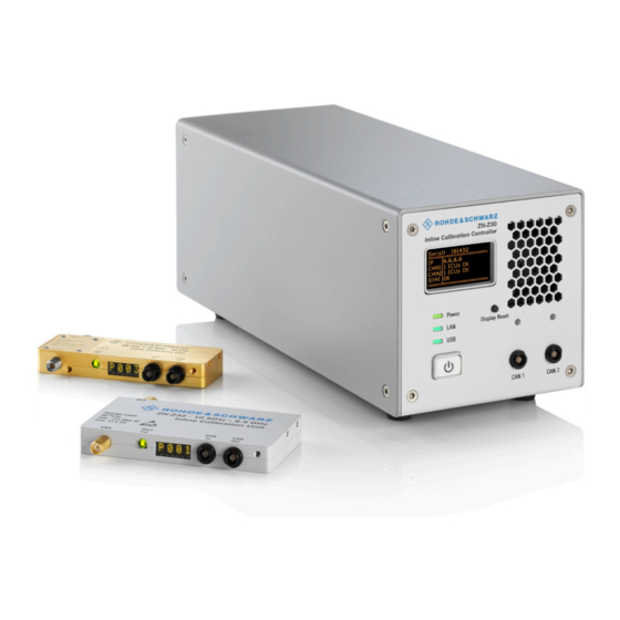
® Introduction R&S ZN-Z3x Introduction The measurement accuracy of a Vector Network Analyzer (VNA) heavily depends on a careful user calibration. Any deviation of the test setup after the calibration process inevitably produces errors. In case of a massive system error correction (e.g. - Page 6 ® Introduction R&S ZN-Z3x Figure 1-2: Inline Calibration Controller With respect to control, the ICC shall act as the master for the connected ICUs. However, in order to avoid unnecessary polling of data that might not have changed (e.g. the temperature of the ICUs) the ICUs themselves are able to send data autonomously.
- Page 7 ® Introduction R&S ZN-Z3x System Overview System Overview An Inline Calibration System R&S ZN-Z3x consists of an Inline Calibration Con- troller R&S ZN-Z30 (order no. 1328.7609.02) and one or more Inline Calibration Units R&S ZN-Z32/Z33, interconnected via CAN bus. Table 1-1: Inline Calibration Units Product Number Name Order No.
- Page 8 ® Introduction R&S ZN-Z3x About this Manual About this Manual The user manual contains the "getting started" chapters as well as descriptions of all instrument functions and of the remote control of the instrument. In addition, it contains notes on preventative maintenance for the R&S ZN-Z3x and on trouble- shooting on the basis of the warnings and error messages that the instrument emits.
-
Page 9: Putting The System Into Operation
® Putting the System into Operation R&S ZN-Z3x Inline Calibration Controller Tour Putting the System into Operation An Inline Calibration System R&S ZN-Z3x consists of a Inline Calibration Control- ler R&S ZN-Z30 and one or more Inline Calibration Units R&S ZN-Z32/Z33. The sections below describe how to put the system into operation and how to establish the required control connections between the system components. - Page 10 ® Putting the System into Operation R&S ZN-Z3x Inline Calibration Controller Tour Mini display The R&S ZN-Z30 offers an OLED status display which provides the following information: ● serial number ● IP-address ● CAN bus 1,2: number of connected Inline Calibration Units, bus status (see on page 36) ICC:CAN<bus>:GET:STATe? Note that in certain error states the ICC may not be able to detect the number...
- Page 11 ® Putting the System into Operation R&S ZN-Z3x Inline Calibration Controller Tour ● Shut down the instrument; see Chapter 2.3.5, "Switching the ICC Off", on page 18. CAN 1,2 Two independent CAN bus interfaces for control connection and power supply of Inline Calibration Units, see Chapter 2.4, "Connect- ICUs", on page 18.
- Page 12 ® Putting the System into Operation R&S ZN-Z3x Inline Calibration Controller Tour Table 2-2: Back panel elements Index Label Description Power switch Fuse drawer (see Chapter 5.2, "Replacing Fuses", on page 47) AC power connector RJ-45 connector to integrate the instrument to a LAN, primarily for remote control purposes.
- Page 13 ® Putting the System into Operation R&S ZN-Z3x Inline Calibration Unit Tour Inline Calibration Unit Tour VNA/DUT RF connectors, 50 Ω, male/female ● SMA for R&S ZN-Z32 ● 2.92 mm (K) for R&S ZN-Z33 It is recommended to use a suitable torque wrench when fastening the RF cables on the test port connectors.
- Page 14 ® Putting the System into Operation R&S ZN-Z3x Preparing the System Table 2-3: Inline Calibration Unit Errors Error code Error description CAN bus error Memory read/write error Temperature error 24 V error Do not connect any further Inline Calibration Unit R&S ZN-Z32/Z33, otherwise the calibration precision (effective system data) can no lon- ger be guaranteed 8 V error...
- Page 15 ® Putting the System into Operation R&S ZN-Z3x Preparing the System Risk of injury and instrument damage The instrument must be used in an appropriate manner to prevent electric shock, fire, personal injury, or damage. ● Do not open the instrument casing. ●...
- Page 16 ® Putting the System into Operation R&S ZN-Z3x Preparing the System Safety precautions Be absolutely sure to follow the instructions in the sections below to prevent injury to people or damage to the system components. This is particularly important the first time that you use the instrument. In addition, be sure to observe the general safety notes at the beginning of this manual.
- Page 17 ® Putting the System into Operation R&S ZN-Z3x Preparing the System 2.3.3 Connecting the ICC to the AC Power Supply Use the supplied power cable to connect the Inline Calibration Controller to the AC power supply. Danger of electric shock The Inline Calibration Controller complies with the specifications for the EN61010-1 protective class, which means that it can only be connected to a power outlet that has a protective contact.
- Page 18 ® Putting the System into Operation R&S ZN-Z3x Connecting ICUs 2.3.5 Switching the ICC Off To switch the R&S ZN-Z30 off, proceed as follows: 1. Press the Standby key on the front of the instrument. The instrument switches to standby mode; only the POWER (standby) button remains active.
- Page 19 ® Putting the System into Operation R&S ZN-Z3x Connecting External Devices R&S ZN-CAN025 (0.25 m length, one end coded 30°, the other coded 0°); other cable lengths and couplers can be ordered separately. Table 2-4: CAN bus control cables / adapters Order no.
- Page 20 ® Putting the System into Operation R&S ZN-Z3x Connecting External Devices 2.5.1 If required, connect the USB connecting cable to the USB type B (slave) port on the rear panel. With direct connection to a master device, a connecting cable A-B (plug type A onto plug type B) must be used.
- Page 21 ® Putting the System into Operation R&S ZN-Z3x Connecting External Devices 2.5.2.3 Point-to-Point Connections Establishing a simple network – a LAN connection between an R&S ZN-Z30 and a computer without integration into a larger network – requires assignment of an IP address for the R&S ZN-Z30 and the computer.
- Page 22 ® Putting the System into Operation R&S ZN-Z3x Connecting External Devices User Manual 1177.6381.02 ─ 03...
-
Page 23: Application
® Application R&S ZN-Z3x Application The Inline Calibration System R&S ZN-Z3x is an innovative solution for in-situ VNA recalibration. Each Inline Calibration Unit (ICU) contains calibration stand- ards that are electronically switched when a calibration is performed. The calibra- tion kit data for these standards are stored in the Inline Calibration Unit, so that the analyzer can calculate the error terms and apply the calibration without any further input. - Page 24 ® Application R&S ZN-Z3x Calibration Accuracy This manual only gives a brief introduction to the Inline Calibration System's connection and use. For detailed information on remote operation refer to the forthcoming Rohde & Schwarz Application Note. Inserting the ICUs into the Signal Path Each Inline Calibration Unit offers two RF connectors: ●...
-
Page 25: Operation
® Operation R&S ZN-Z3x Operation The Inline Calibration System R&S ZN-Z3x is completely remote-controlled, with the Inline Calibration Controller R&S ZN-Z30 providing the management inter- face. Apart from the Display Reset button on the Inline Calibration Controller and Start Cal button on the Inline Calibration Unit it does not provide any means for manual control. - Page 26 ® Operation R&S ZN-Z3x Basic Information on Remote Control Basic Information on Remote Control This chapter contains basic information on remote control of the Inline Calibration System R&S ZN-Z3x. It contains instructions for setting up the Inline Calibration Controller R&S ZN-Z30 for remote control. 4.1.1 Interfaces and protocols The Inline Calibration Controller ("the instrument"...
- Page 27 ® Operation R&S ZN-Z3x Basic Information on Remote Control 4.1.1.1 Commands and Responses Commands are messages that the controller sends to the instrument. They oper- ate the instrument functions and request information. The commands are divided into types based on two criteria: ●...
- Page 28 ® Operation R&S ZN-Z3x Basic Information on Remote Control The TCP/IP network protocol and the network services associated with it are pre- configured on the instrument. To establish the connection, you need the instrument's IP address or computer name. Socket Communication An alternative way for remote control of the Inline Calibration System is to estab- lish simple network communication using sockets (also referred as "Raw Ethernet communication").
- Page 29 ® Operation R&S ZN-Z3x Remote Control Commands ● the R&S ZN-Z30's product ID 0x17B and ● the Inline Calibration Controller's 6-digit serial number, which can be read from the mini display or the label on the back of the particular R&S ZN-Z30). 4.1.2 Status Reporting System The status reporting system stores all information on the instrument's current sta-...
- Page 30 ® Operation R&S ZN-Z3x Remote Control Commands ........................30 *IDN? ........................30 *RST ........................ 30 *SERial? ....................31 ICC:SET:CLOCK ...................31 ICC:WRITE:SETTINGS *IDN? Returns the identification string of the R&S ZN-Z30. Return values: <ID_Str> ROHDE&SCHWARZ,ZN-Z30,<serial>,<fw version>, where <serial> is the 6 digit serial number (see SAP label on the backplane) <fw version>...
- Page 31 ® Operation R&S ZN-Z3x Remote Control Commands ICC:SET:CLOCK Sets date and time at the Inline Calibration Controller. Note that the R&S ZN-Z30 doesn't have a battery and hence date and time have to be set after every power off. Parameters: <TimeStamp>...
-
Page 32: Icc:show:lan:host:name
® Operation R&S ZN-Z3x Remote Control Commands Modified LAN settings are not applied until is executed. To ICC:INIT:LAN make the changes permanent, use to write the ICC:WRITE:SETTINGS current LAN settings to the Inline Calibration Controller..................32 ICC:SET:LAN:HOST:NAME ................32 ICC:SHOW:LAN:HOST:NAME? ................32 ICC:SHOW:LAN:MAC:ADDRESS? .................. -
Page 33: Icc:show:lan:dhcp
® Operation R&S ZN-Z3x Remote Control Commands Return values: <MACAddress> The LAN MAC address is in the format xx-xx-xx-xx-xx-xx, e.g. 00-40-9D-25-EE-0C. Usage: Query only ICC:SHOW:LAN:DHCP? Queries whether DHCP is enabled. Return values: <DHCP> 1: DHCP is enabled 0: DHCP is disabled (static IP configuration) Usage: Query only Manual operation:... -
Page 34: Icc:set:lan:ip
® Operation R&S ZN-Z3x Remote Control Commands Parameters: <GWIP> The IP address of the default gateway in dotted decimal format, e.g. 192.168.1.2. Manual operation: "IP address / Subnet Mask / Standard Gateway" on page 56 ICC:SET:LAN:IP ICC:SHOW:LAN:IP? Sets/queries the LAN IP address. Setting an IP address is only possible with static IP configuration (ICC:SET: LAN:DHCP:OFF). -
Page 35: Icc:set:lan:dnsaddr
® Operation R&S ZN-Z3x Remote Control Commands ICC:SET:LAN:DNSADDR Sets the DNS server. This is only possible with static IP configuration (ICC:SET:LAN:DHCP:OFF). Otherwise the calibration unit answers with a "Deactivate DHCP first!" Note that modified LAN settings are not applied until is execu- ICC:INIT:LAN ted. - Page 36 ® Operation R&S ZN-Z3x Remote Control Commands Suffix: <bus> 1 or 2 Number of the related CAN bus Usage: Event ICC:CAN<bus>:APP:START Broadcasts the "application start" command to connected Inline Calibration Units. This requires the CAN Bus to be in bootloader mode (after a ICC:CAN<bus>: command).
- Page 37 ® Operation R&S ZN-Z3x Remote Control Commands <progress> CAN bus data transfer progress in percent (e.g. transfer of factory characterization data) <err_count> CAN bus error counter Usage: Query only Table 4-3: CAN bus status codes Status Mini display Description code OFF state (e.g.
- Page 38 ® Operation R&S ZN-Z3x Remote Control Commands ICC:GET:ID Initiates the identification of all connected Inline Calibration Units; triggers a broadcast on both CAN busses. The CAN buses must neither be in bootloader mode nor in busy state. Usage: Event Manual operation: "Update ID List"...
- Page 39 ® Operation R&S ZN-Z3x Remote Control Commands 4.2.2.1 ICU Properties Commands to set/get the properties of an individual Inline Calibration Unit (ICU). The ICUs connected to the Inline Calibration Controller can be discovered via and ICC:GET:LIST?. ICC:GET:ID ....................39 ICU:SHOW:STATE? ....................40 ICU:SHOW:TEMP? ....................
- Page 40 ® Operation R&S ZN-Z3x Remote Control Commands Status code Description 5 V error CAN bus functionality degraded, risk of system error Calkit error Calkit data unavailable or unreadable Temperature error, Risk of damaging the device ICU:SHOW:TEMP? <ICU_ID> Queries the last temperature reported by the related ICU Parameters: <ICU_ID>...
- Page 41 ® Operation R&S ZN-Z3x Remote Control Commands Return values: <fw_version> Firmware version of the related ICU Usage: Query only ICU:SECure:ERASe <ICU_ID> Sanitizes the flash memory of the related ICU (i.e. securely erases the user block of data) or queries the sanitization state. Parameters: <ICU_ID>...
- Page 42 ® Operation R&S ZN-Z3x Remote Control Commands Parameters: <ICU_ID> ID of a connected Inline Calibration Unit (see "ICU_ID" on page 38) Usage: Event ICU:CAL:START <ICU_ID> ICU:CAL:STOP <ICU_ID> Starts/stops the calibration logic at the related Inline Calibration Unit (see ICU: SHOW:BUTton:STATE?): ●...
- Page 43 ® Operation R&S ZN-Z3x Remote Control Commands ICU:CAL:STOP IDLE TRIGGERED ICU:CAL:START Push "Start Cal" button ARMED Figure 4-1: "Start Cal" button state transitions The intended use case is a calibration step requiring user interaction, for example if a THROUGH standard has to be connected between the related Inline Calibra- tion Units.
- Page 44 ® Operation R&S ZN-Z3x Remote Control Commands ICU:CALKIT:FACT:READ <ICU_ID> Reads the factory characterization (factory calkit file) from the flash memory of the related Inline Calibration Unit to the SD-Card of the Inline Calibration Control- ler. Caching of factory characterization data over the comparatively slow CAN bus connection (max.
- Page 45 ® Operation R&S ZN-Z3x Remote Control Commands Parameters: <ICU_ID> ID of a connected Inline Calibration Unit (see "ICU_ID" on page 38) Usage: Event Manual operation: "Read User Characterization R&S ZN-Z32/Z33" on page 55 ICU:CALKIT:USER:WRITE <Dest_UCkitFile> Writes a user calkit file from the SD-Card of the Inline Calibration Controller to the flash memory of the related Inline Calibration Unit.
- Page 46 ® Operation R&S ZN-Z3x Remote Control Commands ICU:CALKIT:USER:DELete <Src_UCkitNo> Deletes one of the user characterization files User1.zip, ..., User<N>.zip from the flash memory of the related Inline Calibration Unit (see ICU:CALKIT: on page 45). USER:WRITE Parameters: <Src_UCkitNo> String identifying the related ICU and the user calkit file to be deleted.
-
Page 47: Maintenance
® Maintenance R&S ZN-Z3x Replacing Fuses Maintenance Inline Calibration Unit Recharacterization The Inline Calibration Units R&S ZN-Z32/Z33 need to be recharacterized in inter- vals of one year. Other maintenance work is essentially limited to cleaning the Inline Calibration System components and replacing fuses in the Inline Calibration Controller. - Page 48 ® Maintenance R&S ZN-Z3x Service work To replace the fuses 1. Use a small screwdriver to bend the small clamps on both sides of the fuse drawer inward so that you can lift the fuse drawer out of its slot. 2.
- Page 49 ® Maintenance R&S ZN-Z3x Packing and storage Packing and storage The storage temperature for the R&S ZN-Z3x is specified in the data sheet. When storing for longer periods, protect the calibration system components from dust. Prior to transport or shipping, pack the calibration system components just as they were originally packed.
- Page 50 ® Maintenance R&S ZN-Z3x Packing and storage User Manual 1177.6381.02 ─ 03...
-
Page 51: Zn-Z3X User Tool
® ZN-Z3x User Tool R&S ZN-Z3x Software Installation ZN-Z3x User Tool The ZN-Z3x User can be found on the User Documentation CD-ROM that is ship- ped with the R&S ZN-Z30. It offers the following functions: ● Connect to one or more Inline Calibration Controllers R&S ZN-Z30 via USB ●... - Page 52 ® ZN-Z3x User Tool R&S ZN-Z3x Getting Started Figure 6-1: USB device driver installation Getting Started 1. Start the R&S ZN-Z30 as described in Chapter 2.3.4, "Turning the ICC On and Starting", on page 17. 2. Connect the R&S ZN-Z30 via USB, as described in Chapter 2.5.1, "USB", on page 20.
- Page 53 ® ZN-Z3x User Tool R&S ZN-Z3x Device Panel Device Panel The panel above the tabs allows to select one of the connected R&S ZN-Z30 and displays its basic properties (serial number, firmware version, number of connec- ted Inline Calibration Units R&S ZN-Z32/Z33). After Inline Calibration Controllers have been connected or disconned, the list of available devices must be updated manually using the "Rescan"...
- Page 54 ® ZN-Z3x User Tool R&S ZN-Z3x Test Tab Identification String The line of text below the colored Rohde&Schwarz logo identifies a connected R&S ZN-Z30 by the following string: ZN-Z30, Serial: <serial number>, Version: <FW version> Remote command: *IDN? *SERial? Connected R&S ZN-Z32/Z33 This line of text lists the number of connected Inline Calibration Units (after press- ing the Update ID List...
- Page 55 ® ZN-Z3x User Tool R&S ZN-Z3x Test Tab R&S ZN-Z32/Z33 ID List Display the hexadecimal IDs of the Inline Calibration Units connected to the selected R&S ZN-Z30 (after pressing the Update ID List button). Remote command: ICC:GET:LIST? Update ID List Starts the identification of all Inline Calibration Units connected to the selected R&S ZN-Z30 and refreshes the R&S ZN-Z32/Z33 ID...
- Page 56 ® ZN-Z3x User Tool R&S ZN-Z3x Settings Tab Write User Characterization R&S ZN-Z32/Z33 Reads the factory characterization data of the related Inline Calibration Units (from the SD card of the selected R&S ZN-Z30) and saves them to a user-defined folder. Remote command: ICU:CALKIT:USER:WRITE Settings Tab...
- Page 57 ® ZN-Z3x User Tool R&S ZN-Z3x Settings Tab Write all settings to ZN-Z30 (permanent) to make the changes persistent. Remote command: ICC:SHOW:LAN:IP? ICC:SET:LAN:IP ICC:SHOW:LAN:SNMask? ICC:SET:LAN:SNMask ICC:SHOW:LAN:GW? ICC:SET:LAN:GW Hostname Gets/sets the R&S ZN-Z30's hostname (20 characters). Write all settings to ZN-Z30 (permanent) to make the changes persistent.
- Page 58 ® ZN-Z3x User Tool R&S ZN-Z3x System Monitor Tab System Monitor Tab The "System Monitor" tab displays the IDs, temperatures and firmware versions of the Inline Calibration Units connected to the selected R&S ZN-Z30. Use the "Update" button to retrieve the latest monitoring results from the selected Inline Calibration System.
-
Page 59: List Of Commands
® List of Commands R&S ZN-Z3x List of Commands *IDN?............................30 *RST.............................30 *SERial?............................30 ICC:CAN<bus>:APP:START......................36 ICC:CAN<bus>:BOOTloader:START...................36 ICC:CAN<bus>:GET:STATe?...................... 36 ICC:CAN<bus>:RST........................35 ICC:GET:ID..........................38 ICC:GET:LIST?..........................38 ICC:INIT:LAN..........................35 ICC:SET:CLOCK..........................31 ICC:SET:LAN:DHCP:OFF......................33 ICC:SET:LAN:DHCP:ON......................33 ICC:SET:LAN:DNSADDR......................35 ICC:SET:LAN:GW........................33 ICC:SET:LAN:HOST:NAME......................32 ICC:SET:LAN:IP...........................34 ICC:SET:LAN:SNMask.........................34 ICC:SHOW:LAN:DHCP?......................33 ICC:SHOW:LAN:GW?........................33 ICC:SHOW:LAN:HOST:NAME?....................32 ICC:SHOW:LAN:IP?........................34 ICC:SHOW:LAN:MAC:ADDRESS?....................32 ICC:SHOW:LAN:SNMask?...................... - Page 60 ® List of Commands R&S ZN-Z3x ICU:SHOW:BUTton:STATE?....................... 42 ICU:SHOW:STATE?........................39 ICU:SHOW:TEMP?........................40 ICU:SHOW:VAR?.........................40 User Manual 1177.6381.02 ─ 03...
-
Page 61: Index
® Index R&S ZN-Z3x Index Symbols *IDN ............30 *RST ............30 Port number ........41 *SERIAL ..........30 Inline Calibration Unit Firmware version ........ 40 Hardware variant ........ 40 identify ..........38 Calibration Start Cal button state ......42 MATCH .......... - Page 62 ® Index R&S ZN-Z3x Reset CAN bus ..........35 Instrument Settings ......30 RF Connectors ........13 Serial number .......... 30 Settings Clock ........... 31 Save ............31 Start Application CAN bus ..........36 Temperature Show ........... 40 Through-connection ........ 41 rear panel ..........11 Remote control interface .....26 User Characterization...
Need help?
Do you have a question about the R&S ZN-Z3x and is the answer not in the manual?
Questions and answers