Advertisement
Quick Links
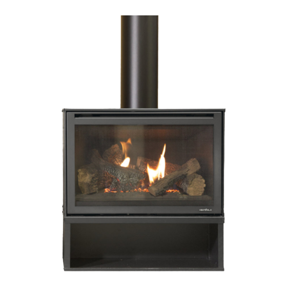
i30-X Freestanding
Assembly Instructions
These instructions are to be used in conjunction with the general i30-X installation manual that is
shipped with the unit.
DO NOT PLACE ARTICLES ON OR AGAINST THIS APPLIANCE
DO NOT USE OR STORE FLAMMABLE MATERIALS NEAR THIS APPLIANCE
DO NOT SPRAY AEROSOLS IN THE VICINITY OF THIS APPLIANCE WHILE IT IS IN OPERATION
DO NOT MODIFY THIS APPLIANCE
Further information can be found at:
https://jetmastervic.com.au/brochures-specifications/
Page 1
Advertisement

Subscribe to Our Youtube Channel
Related Manuals for Heat & Glo i30-X


Summary of Contents for Heat & Glo i30-X
- Page 1 Freestanding Assembly Instructions These instructions are to be used in conjunction with the general i30-X installation manual that is shipped with the unit. DO NOT PLACE ARTICLES ON OR AGAINST THIS APPLIANCE DO NOT USE OR STORE FLAMMABLE MATERIALS NEAR THIS APPLIANCE...
- Page 2 Freestanding case Components Description Base Rear Panel Left Panel Right Panel Top Panel - spigot attached Black self tapping screws (Pack of 30) Ceiling Ring Plastic gromet The fireplace will require the I30X flex liner flue kit together with 8inch solid flue to encase the flexible flue up to the cowl.
- Page 3 Base - Linear and Stretch Components Linear pedestal width - 805mm Stretch pedestal width - 1105mm Description Base Rear Panel Left Panel Right Panel Top Panel Black self tapping screws (Pack of Nuts for securing top panel to sides NOTE: If installing the fireplace on either the linear or stretch base, assemble the base first and then assemble the casing on top.
- Page 4 Linear and stretch base Assembly instructions Step1. Unbox the base and identify each component using the table on page 3. Step 2. Locate and position the top panel on a clean and flat surface upside down. The side panels are attached using the supplied nuts (x6) which are fixed to captive welded bolts on the inside of the top panel.
- Page 5 Freestanding case Assembly instructions Step1. Unbox the freestanding case and identify each component using page 2 as reference. Step 2. Locate and position the base panel on a flat and slightly elevated working surface. The base panel front is the flat edge.
- Page 6 Fix the base to the floor using relevant materials. Clearance requirements 50mm rear clearance Plan view 50mm side clearance 1000mm clearance above 50mm clearance to flue Front view Zero clearance required under the casing Refer to current i30-X AU manual for floor protection requirements Page 6...
- Page 7 Freestanding case Assembly instructions Step 7. Mark the ceiling for the flue penetration using a plumb bob or laser guide and rivet together the Optional shielding if required unpainted 8inch gal. If the exposed flue requires fixing, black rivets are recommended.
- Page 8 Step 10. Position the i30-X fireplace into the casing on an angle so as to be able to feed both the flexible gas line and power cord through the back panel.
- Page 9 Page 9...
- Page 10 If an offset is required below the ceiling, the painted 8inch flue must be riveted together and appropriately braced within the ceiling cavity Page 10...
- Page 11 Freestanding Unit Dimensions 804mm 473.5mm 470mm Page 11...
- Page 12 Freestanding Base Dimensions LINEAR BASE STRETCH BASE...
- Page 13 Jetmaster Heat & Glo 444 Swan Street Richmond PH: 1300 219 875 www.jetmastervic.com.au...
Need help?
Do you have a question about the i30-X and is the answer not in the manual?
Questions and answers