Table of Contents
Advertisement
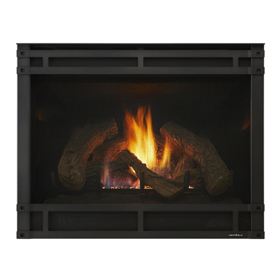
Models:
SL-550TV-D, SL-550TV-IPI-D
SL-750TV-D, SL-750TV-IPI-D
SL-950TV-D, SL-950TV-IPI-D
• Important operating
a n d m a i n t e n a n c e
instructions included.
WARNING: If the information in these
instructions is not followed exactly, a fi re
or explosion may result causing property
damage, personal injury, or death.
• Do not store or use gasoline or other fl am-
mable vapors and liquids in the vicinity of
this or any other appliance.
• What to do if you smell gas
- Do not try to light any appliance
- Do not touch any electrical switch. Do not
use any phone in your building.
- Immediately call your gas supplier from a
neighbor's phone. Follow the gas suppli-
er's instructions.
- If you cannot reach your gas supplier, call
the fi re department.
• Installation and service must be performed
by a qualifi ed installer, service agency, or the
gas supplier.
In the Commonwealth of Massachusetts:
• installation must be performed by a licensed plumber
or gas fi tter;
• a CO detector shall be installed in the room where the
appliance is installed.
CAUTION
DO NOT DISCARD THIS MANUAL
• Read, understand and follow
these instructions for safe
installation and operation.
Heat & Glo • SL-550 / 750 / 950TV-D • 2053-985 Rev. H • 9/06
Owner's Manual
Installation and Operation
• Leave this manual with
party responsible for use
and operation.
WARNING
HOT! DO NOT TOUCH.
SEVERE BURNS MAY RESULT.
CLOTHING IGNITION MAY RESULT.
Glass and other surfaces are hot during
operation and cool down.
• Keep children away.
• CAREFULLY SUPERVISE children in same room as
appliance.
• Alert children and adults to hazards of high
temperatures.
• Do NOT operate with protective barriers open or
removed.
• Keep clothing, furniture, draperies and other
combustibles away.
This appliance has been supplied with an integral barrier
to prevent direct contact with the fi xed glass panel. Do
NOT operate the appliance with the barrier removed.
Contact your dealer or Hearth & Home Technologies if the
barrier is not present or help is needed to properly install one.
This appliance is only for use with the type(s) of gas indicated
on the rating plate.
Installation and service of this appliance should be
performed by qualifi ed personnel. Hearth & Home
Technologies suggests NFI certifi ed or factory-trained
professionals, or technicians supervised
by an NFI certifi ed professional.
1
Advertisement
Table of Contents

Related Manuals for Heat & Glo SL-550TV-D


Summary of Contents for Heat & Glo SL-550TV-D
- Page 1 Models: SL-550TV-D, SL-550TV-IPI-D SL-750TV-D, SL-750TV-IPI-D SL-950TV-D, SL-950TV-IPI-D • Important operating a n d m a i n t e n a n c e instructions included. WARNING: If the information in these instructions is not followed exactly, a fi re or explosion may result causing property damage, personal injury, or death.
-
Page 2: Homeowner Reference Information
Read this manual before installing or operating this appliance. Please retain this owner’s manual for future reference. Congratulations on selecting a Heat & Glo gas appliance —an elegant and clean alternative to wood burning appliances. The Heat & Glo gas appliance you have selected is designed to provide the utmost in safety, reliability, and effi... -
Page 3: Table Of Contents
Section 1: Listing and Code Approvals A. Appliance Certifi cation ... 4 B. Glass Specifi cations ... 4 C. BTU Specifi cations ... 4 D. High Altitude Installations ... 5 E. Non-combustible Materials Specifi cation... 5 F. Combustible Materials Specifi cation... 5 Section 2: Getting Started A. -
Page 4: Listing And Code Approvals
Listing and Code Approvals Appliance Certifi cation MODELS: SL-550TV-D, SL-750TV-D, SL-950TV-D, LABORATORY: Underwriters Laboratories, Inc. (UL) TYPE: B-Vent Decorative STANDARD: ANSI Z21.50-2002 • CGA2.2 This product is listed to ANSI standards for “Vented Gas Fireplaces” and “Gas Fired Appliances for Use at High Altitudes”. -
Page 5: High Altitude Installations
D. High Altitude Installations U.L. Listed gas appliances are tested and approved without requiring changes for elevations from 0 to 2000 feet in the U.S.A. and Canada. When installing this appliance at an elevation above 2000 feet, it may be necessary to decrease the input rating by changing the existing burner orifi... -
Page 6: Getting Started
Getting Started A. Design and Installation Considerations Heat & Glo B-type vent gas appliances are designed to operate with all exhaust gases expelled to the outside of the building, and combustion air pulled from the room. CAUTION Check building codes prior to installation. •... -
Page 7: Negative Pressure
B. Negative Pressure WARNING Asphyxiation Risk. Negative pressure can cause spillage of • combustion fumes and soot. • Fireplace needs to draft properly for safety. Draft is the pressure difference needed to vent fi replaces successfully. Considerations for successful draft include: •... -
Page 8: Tools And Supplies Needed
C. Tools and Supplies Needed Before beginning the installation be sure that the following tools and building supplies are available. Reciprocating saw Framing material Pliers Hi temp caulking material Hammer Gloves Phillips screwdriver Framing square Flat blade screwdriver Electric drill and bits (1/4 in.) Plumb line Safety glasses Level... -
Page 9: Framing And Clearances
• Actual installation may vary due to individual design preference. A. Selecting Appliance Location When selecting a location for your appliance it is important to consider the required clearances to walls (see Figure 3.1). TOP VENT Model Inches SL-550TV-D Millimeters Inches SL-750TV-D Millimeters Inches SL-950TV-D Millimeters In addition to these framing dimensions, also reference the following sections: •... -
Page 10: Constructing The Appliance Chase
If the appliance is being installed on a cement slab, a layer of plywood may be placed underneath to prevent conducting cold up into the room. Models Inches SL-550TV-D Inches SL-750TV-D Inches SL-950TV-D Figure 3.2 Clearances to Combustibles Heat &... -
Page 11: Mantel Projections
D. Mantel Projections 12 INCHES (305mm) NON-COMBUSTIBLE 12 INCHES MATERIAL ONLY (305mm) 1/2 INCH (13mm) TOP FRONT EDGE OF FIREPLACE Figure 3.3 Clearances to Mantels or other Combustibles above Appliance Heat & Glo • SL-550 / 750 / 950TV-D • 2053-985 Rev. H • 9/06... -
Page 12: Termination Locations
Termination Locations A. Vent Termination Minimum Clearances WARNING Fire Risk. Explosion Risk. Maintain vent clearance to combustibles as specifi ed. • Do not pack air space with insulation or other materials. Failure to keep insulation or other materials away from vent pipe may cause fi re. 8 FEET LOWEST DISCHARGE... -
Page 13: Vent Information And Diagrams
These models require the following size B-vent double wall, or single wall rigid or fl ex vent pipe. Models SL-550TV-D, SL-550TV-IPI-D SL-750TV-D, SL-750TV-IPI-D SL-950TV-D, SL-950TV-IPI-D • B-vent pipe MUST be used when the vent system is within combustible construction. - Page 14 WARNING Fire Risk. Explosion Risk. Insulation and other combustibles must not infringe on clearances. • ALWAYS maintain specifi ed clearances around venting and fi restop systems. • Install fi restops as specifi ed. Failure to keep insulation or other material away from vent pipe may cause fi...
-
Page 15: Vent Clearances And Framing
Vent Clearances and Framing A. Pipe Clearances to Combustibles WARNING Fire Risk. Explosion Risk. Maintain vent clearance to combustibles as specifi ed. • Do not pack air space with insulation or other materials. • National building codes recommend using attic shield to keep loose materials/insulation from contacting vent. -
Page 16: Appliance Preparation
Appliance Preparation CAUTION Sharp Edges • Wear protective gloves and safety glasses dur- ing installation. A. Installing Outside Air Kit Damper Assembly WARNING Asphyxiation Risk. Fire Risk. Do NOT draw outside combustion air from: • Wall, fl oor or ceiling cavity. •... -
Page 17: Securing And Leveling Appliance
C. Securing and Leveling Appliance WARNING Fire Risk. • Prevent contact with sagging, loose insulation. • Do NOT install against combustible materials such as exposed insulation, plastic and insulation backer. The diagram shows how to properly position, level, and secure the appliance (see Figure 7.3). Nailing tabs are pro- vided to secure the appliance to the framing members. -
Page 18: Installing Vent Pipe
Installing Vent Pipe A. Assembly of Vent Sections This B-Vent appliance requires 5-inch (SL-550/750TV-D) or 6-inch (SL-950TV-D) B-vent double-wall pipe. Follow the pipe manufacturer’s installation guidelines when installing the unit. This will ensure proper operation and prevent safety hazards. WARNING Fire Risk Exhaust Fumes Risk Impaired Performance of Appliance... -
Page 19: Section 9: Gas Information A. Fuel Conversions
Gas Information A. Fuel Conversions Before making gas connections ensure that appliance be- ing installed is compatible with the available gas type. Any natural or propane gas conversions necessary to meet the appliance and locality needs must be made by a qualifi... - Page 20 • Ensure that gas line does not come in contact with outer wrap of appliance. Follow local codes. • Incoming gas line should be piped into the valve com- partment and connected to the 1/2 inch connection on the manual shutoff valve. WARNING Fire or Explosion Hazard •...
-
Page 21: Electrical Information
Electrical Information A. Recommendation for Wire This appliance requires 110-120 VAC be wired to the junction box either for use of optional accessories (stand- ing pilot ignition) or for proper operation of the appliance (Intellifi re ignition). Refer to Figure 10.1 to determine if the appliance uses an Intellifi... -
Page 22: Standing Pilot Ignition System Wiring
IGNITION MODULE 3 VAC TRANSFORMER 3V PLUG-IN BATTERY PACK TEMP SENSOR THERMOSTAT WIRE ASSEMBLY Figure 10.2 Intellifi re Pilot Ignition (IPI) Wiring Diagram D. Standing Pilot Ignition System Wiring This standing pilot ignition system wiring does not require a 110 VAC supply to operate. WHITE PILOT PIEZO... -
Page 23: Junction Box Installation
E. Junction Box Installation If the box is being wired from the OUTSIDE of the appliance: • Remove the cover plate located on the outer shell right side (see Figure 10.4). • Install the supplied Romex™ connector in the cover plate. -
Page 24: Finishing A. Mantel Projections
Finishing A. Mantel Projections Figure 11.1 shows the minimum vertical and corresponding maximum horizontal dimensions of appliance mantels or other combustible projections above the top front edge of the appliance. NON-COMBUSTIBLE MATERIAL ONLY 1/2 INCH (13mm) TOP FRONT EDGE OF FIREPLACE Figure 11.1 Clearances to Mantels or other Combustibles above Appliance B. -
Page 25: Appliance Setup
Appliance Setup A. Remove Shipping Materials Remove shipping materials from inside or underneath the fi rebox. B. Remove Grate Shipping Support • Remove the log pack and hood, if applicable. • Bend top retaining tab of grate shipping support into vertical position (see Figure 12.1). -
Page 26: Positioning The Logs
Slide the right edge of log #2 forward until it touches the grate. Heat & Glo • SL-550 / 750 / 950TV-D • 2053-985 Rev. H • 9/06 Log Set Assembly: LOGS-SL550-D Models: SL-550TV-D Carefully remove the logs from the packaging. CAUTION: Logs are fragile! Place log #1 onto the grate bars so that the notches in the bottom of the log fi... - Page 27 NOTCH LOG #3 (SRV2044-703): Slide the left edge of log #3 forward until it touches the grate. TAB LOCATOR LOG #4 (SRV2044-701): grate as shown. TAB LOCATOR LOG #5 (SRV2044-702): grate as shown. Heat & Glo • SL-550 / 750 / 950TV-D • 2053-985 Rev. H • 9/06 Place log #3 on the left two grate bars using the notch on the bottom of log #3.
- Page 28 If the gas logs have been factory installed they should not need to be positioned. If the logs have been packaged separately, refer to the following instructions. NOTCHES LOG #1 (SRV2045-700): #1 up to the front tabs for NG. Slide it back until top of log touches the back of the fi replace for LP. NOTCHES LOG #2 (SRV530-719): Place log #2 on the right two grate bars using the notches in the bottom of the log.
- Page 29 RAISED FLAT SPOTS NOTCHES RAISED FLAT SPOTS LOG #3 (SRV530-718): Place log #3 on the left two grate bars using the notches in the bottom of the log. Position log parallel to log #1 and on the same line as log #2. Left edge of log should rest between grate bar and second tab.
-
Page 30: Glass Assembly
When overlapping on both sides, leave enough space so that the bottom grille can be lowered and the trim door removed. K. Hood Hood is included with the front and required in all installations. L. Shutter Settings SL-550TV-D SL-750TV-D SL-950TV-D Models 1/4 in. 1/4 in. 3/8 in. -
Page 31: Operating Instructions
Operating Instructions A. Before Lighting Appliance Before lighting this appliance determine if it has a Standing Pilot or Intellifi re ignition system by opening the control access panel to view wiring system and gas valve. If this appliance has a red or black ignitor button (see Figure 10.1) this appliance has a Standing Pilot ignition system. -
Page 32: To Turn Off Gas To Appliance
C. Lighting Appliance Intellifi re Ignition FOR YOUR SAFETY READ BEFORE LIGHTING WARNING: If you do not follow these instructions exactly, a fi re or explosion may result causing property damage, personal injury or loss of life. A. This appliance is equipped with an intermittent pilot ignition (IPI) device which automatically lights the burner. -
Page 33: Standing Pilot Ignition
Standing Pilot Ignition FOR YOUR SAFETY READ BEFORE LIGHTING WARNING: If you do not follow these instructions exactly, a fi re or explosion may result causing property damage, personal injury or loss of life. A. This appliance has a pilot which must be lighted by hand. -
Page 34: After Appliance Is Lit
D. After Appliance is Lit Initial Break-in Procedure When you light the appliance, you may notice that it pro- duces heat which does have an associated odor or smell. If you feel this odor is excessive it may require the initial three to four hour continuous burn on high followed by a second burn up to 12 hours to fully drive off any odor from paint and lubricants used in the manufacturing process. -
Page 35: Troubleshooting
Troubleshooting With proper installation, operation, and maintenance your gas appliance will provide years of trouble-free service. If you do experience a problem, this troubleshooting guide will assist a qualifi ed service person in the diagnosis of a problem and the corrective action to be taken. - Page 36 Troubleshooting (continued) Symptom Possible Cause 3..Continued c. Defective valve. d. Plugged burner orifi ce. e. Wall switch or wires are defective. 4. Frequent pilot a. Pilot fl ame may be too outage problem. high or too low, or blowing out (high pressure), causing pilot safety to drop out.
-
Page 37: Intellifi Re Ignition System
B. Intellifi re Ignition System Symptom Possible Causes 1. The ignitor/ a. Incorrect wir- module makes ing. noise, but no spark. b. Loose connec- tions or electri- cal shorts in the wiring. c. Ignitor gap is too large. d. Faulty module. 2. - Page 38 Intellifi re Ignition System - (continued) Symptom Possible Causes 3..continued d. Damaged pilot assembly or dirty sensor rod. e. Faulty module. 4. Pilot sparks, but a. Correct gas supply. Verify that incoming gas line ball valve is “open”. Verify that inlet pressure Pilot will not light.
-
Page 39: Maintaining And Servicing Appliance
Maintaining and Servicing Appliance Although the frequency of appliance servicing and maintenance will depend on use and the type of installation, a qualifi ed service technician should perform an appliance check-up at the beginning of each heating season. WARNING Risk of injury or property damage. Before servicing: •... - Page 40 Inspect Doors, Surrounds and 1. Assess condition of screen and replace as necessary. Recommend addition of screen if one is not Fronts present. 2. Inspect for scratches, dents or other damage and repair as necessary. 3. Verify no obstructions to airfl ow through the louvers. 4.
-
Page 41: Reference Materials
Dimensions are actual appliance dimensions. Use for reference only. For framing dimensions and clearances refer to Section 3. GAS LINE ACCESS Figure 16.1 Appliance Dimensions Appliance Dimensions Table Inches 32-1/2 SL-550TV-D Millimeters Inches 37-3/4 20-1/2 34-1/2 3-1/2 SL-750TV-D Millimeters 1040 Inches... -
Page 42: Service Parts
Part number list on following page. Heat & Glo • SL-550 / 750 / 950TV-D • 2053-985 Rev. H • 9/06 B. Service Parts (NG, LP) Exploded Parts Diagram Log Set Assembly SL-550TV-D Beginning Manufacturing Date: 1-06 Ending Manufacturing Date: ______... - Page 43 10-06 446-511 POST 10-06 2103-511 10-06 446-511 POST 10-06 2103-512 10-06 SRV485-301 POST 10-06 050-721 386-122A TUP-GBK-12 10-06 NGK-550TR-C POST 10-06 NGKS-550TR-D 10-06 LPK-550TR-C POST 10-06 LPKS-550TR-D NGK-550IPIC LPK-550IPIC GFK-160A BAF-VERT WSK-21 WSK-21-W SL-550TV-D AVAILABLE TO SHIP IN 24 HOURS...
- Page 44 Part number list on following page. Heat & Glo • SL-550 / 750 / 950TV-D • 2053-985 Rev. H • 9/06 Service Parts (NG, LP) Exploded Parts Diagram Log Set Assembly SL-750TV-D...
- Page 45 Service Parts List IMPORTANT: THIS IS DATED INFORMATION. The most current information is located on your dealers VIP site. When ordering, supply serial and model numbers to ensure correct service parts. ITEM COMMON PARTS Burner Orifi ce NG (#42C) Burner Orifi ce LP (#53C) Mesh Assembly Burner NG, LP Glass Door Assembly...
- Page 46 Part number list on following page. Heat & Glo • SL-550 / 750 / 950TV-D • 2053-985 Rev. H • 9/06 Service Parts (NG, LP) Exploded Parts Diagram Log Set Assembly SL-950TV-D Beginning Manufacturing Date: 1-06 Ending Manufacturing Date: ______...
- Page 47 Service Parts List IMPORTANT: THIS IS DATED INFORMATION. The most current information is located on your dealers VIP site. When ordering, supply serial and model numbers to ensure correct service parts. ITEM COMMON PARTS Burner Orifi ce NG (#42C) Burner Orifi ce LP (#53C) Mesh Assembly Burner NG, LP Glass Door Assembly...
- Page 48 SL-550 / 750 / 950TV-D-IPI Service Parts Beginning Manufacturing Date: (NG, LP) Exploded Parts Diagram Ending Manufacturing Date: Intermittent Pilot Ignition Valve Assembly Heat & Glo • SL-550 / 750 / 950TV-D • 2053-985 Rev. H • 9/06...
- Page 49 Service Parts (NG, LP) Exploded Parts Diagram ITEM COMMON PARTS Jumper Wires Thermostat Wire Assembly Burner Neck Gasket Pilot Assembly NG Pilot Assembly LP Valve Bracket Valve Plate Gasket Flex Ball Valve Assembly Valve NG Valve LP Flexible Gas Connector Module Module Wire Assembly Battery Pack...
- Page 50 Heat & Glo • SL-550 / 750 / 950TV-D • 2053-985 Rev. H • 9/06 Service Parts (NG, LP) Exploded Parts Diagram Standing Pilot Ignition Valve Assembly SL-550 / 750 / 950TV-D Beginning Manufacturing Date: Ending Manufacturing Date:...
- Page 51 Service Parts (NG, LP) Exploded Parts Diagram ITEM COMMON PARTS Piezo Ignitor Burner Neck Gasket Thermostat Wire Assembly Pilot Assembly NG Pilot Assembly LP Valve Bracket Valve Plate Gasket Flex Ball Valve Assembly Valve NG Valve LP Flexible Gas Connector Pilot Bracket High Limit Switch Jumper Wires...
-
Page 52: Warranty
C. Limited Lifetime Warranty HEAT & GLO GAS APPLIANCE PRODUCTS BASIC ONE-YEAR WARRANTY. HEAT & GLO, a brand of HEARTH & HOME TECHNOLOGIES INC., located at 20802 Kensington Boulevard, Lakeville, MN 55044, (“HEAT & GLO”) warrants to the original owner that your new HEAT & GLO Gas Appliance (the “Product”) will be free from defects in materials and workmanship for a period of one year from the date of installation. -
Page 53: Contact Information
D. Contact Information Please contact your Heat & Glo dealer with any questions or concerns. For the location of your nearest Heat & Glo dealer, ________________________________________________________________________________ ________________________________________________________________________________ ________________________________________________________________________________ ________________________________________________________________________________ ________________________________________________________________________________ ________________________________________________________________________________ ________________________________________________________________________________ ________________________________________________________________________________ ________________________________________________________________________________ • Important operating a n d m a i n t e n a n c e instructions included.
Need help?
Do you have a question about the SL-550TV-D and is the answer not in the manual?
Questions and answers