Advertisement
Quick Links
Advertisement

Subscribe to Our Youtube Channel
Related Manuals for Paxton BLU Expansion Controller


Summary of Contents for Paxton BLU Expansion Controller
- Page 1 Ins-60006-GD-US Expansion Controller Installation Guide...
- Page 2 RECEIVING INSPECTION - Remove any traces of packing material from the unit as such debris may create a fire or shock hazard. Unpack the unit with care and inspect for transit damage. If damage is suspected, the unit must not be used or tested, but you should immediately contact Paxton technical support to assist in troubleshooting or to provide return authorization.
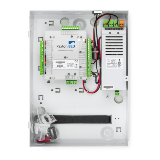
- Page 3 Mounting This housing should be fixed to the surface with suitable fasteners; screws and wall plugs are provided for this in the fitting kit. Also provided are cable ties to secure the cabling and a smaller securing screw for the lid.
-
Page 4: Power Supply
General purpose inputs (contact closure) and outputs (12V, 0.25A max) Power Supply Fail secure lock * Door 1 Reader/Keypad Diode Expansion controller Door contact 1 Exit button 1 (push to make) † Door 2 Reader/Keypad Tamper switch (cabinet) * For a fail safe lock (maglock), wire 12V-24V to the ‘N.C. -
Page 5: Led Diagnostics
Connecting the Paxton BLU Expansion Controller Wire the components to the Paxton BLU Expansion Controller as shown on page 4. Power up the unit and wait for the OK LED heartbeat. If there is a fault with the installation or the unit then the diagnostic LEDs (see above) may well show the fault type enabling you to report or rectify the problem before proceeding. - Page 6 Connecting to Paxton BLU Expansion Controllers via RS485 Data Connection You can connect up to a maximum of 24 Paxton BLU Expansion units to one Master unit (for a total of 50 doors). The Master unit handles all communication with the outside world. Mulitple Master units can be installed on a single site. These can be logically grouped in the software to appear as a single site.
- Page 7 Install the Installer Tool software. This is available to download from the Help page of your installer login to Paxton BLU. You may wish to create a desktop shortcut for this application.
-
Page 8: Firmware Update
You have now completed the initial configuration of the expansion controller, power cycle the unit and log into your Paxton BLU account (my. paxton-blu.com), go to Help and select Quick Start Guide to assist you in setting up the controller in your customer and site. -
Page 9: Specifications
Specifications Electrical Voltage 11V DC 24V DC (+20%) PCB Current (depending on activity) 200mA Relay switchable voltage 24V DC (+20%) Relay switchable current General purpose outputs OUT-1, OUT-2 0.25A@12V DC Combined reader port output current 500mA Environment Operating temperature - Battery limits 0°C - 32 °F 55°C - 131°F Weatherproof... - Page 10 Events stored in controller with no server connection 200,000 Dimensions Controller 4 1/64 inch (W) 4 3/4 inch (H) 1 inch (D) Cabinet 9 1/4 inch (W) 12 1/2 inch (H) 3 1/8 inch (D)
- Page 12 Made in the UK Ins-60006-GD-US Managed access controller Expansion 837-520-US/838-621-US © Paxton Ltd 1.0.3 18/08/2017...
Need help?
Do you have a question about the BLU Expansion Controller and is the answer not in the manual?
Questions and answers