Table of Contents
Advertisement
30/08/2012
Ins-30080 Net2 plus control unit
Technical Support
01273 811011
Technical help is available:
Documentation on all Paxton products can be found on our website - http://www.paxton.co.uk/
The Net2 plus can be connected to the PC via an RS485 data line or a TCP/IP connection.
This unit requires the controlling PC to be running Net2 v4.14 or later software.
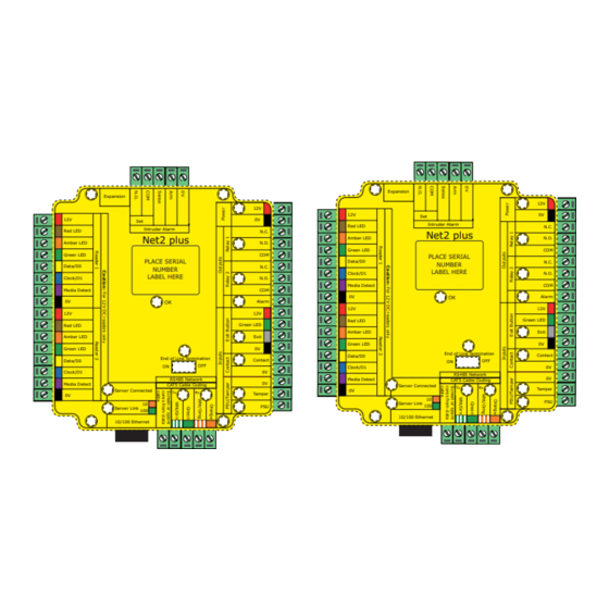
Wiring
Reader/keypad
The Net2 plus ACU has 2 reader ports and
3 output relays, but can control just one
door. The configuration of one control
unit per door greatly simplifies installation
and is ultimately highly cost effective.
LED indications
12V
Relay 1
Relay 2
Alarm
Exit
Contact
Tamper
PSU
OK
Termination
Rx
Tx
Server Connected
Server Link
Intruder alarm integration
12V
Red LED
Amber LED
Green LED
Data/D0
Clock/D1
Media Detect
0V
12V
Red LED
Amber LED
Green LED
Data/D0
Clock/D1
Media Detect
0V
Switchable
120 ohm
resistors
TCP/IP patch lead
(Green)
- Power LED.
(Orange)
- The relay is energised - (N.O./COM contacts are closed).
(Orange)
- The relay is energised - (N.O./COM contacts are closed).
(Red)
- 12V Alarm output is active.
(Orange)
- The exit button contacts are closed.
(Orange)
- The door contacts are closed.
(Orange)
- The tamper contacts are closed.
(Orange)
- The PSU contacts are closed.
(Green flash)
- The internal software is running.
(Red)
- The on-board resistors are in place across the RS485 data pairs.
(Red)
- The ACU is receiving data (TCP/IP or RS485) - See also FAQ section.
(Green)
- The ACU is responding to data - (TCP/IP or RS485).
(Green)
- The TCP/IP interface is communicating with the PC Net2 server.
- Green = 100 Mbit/s : Orange = 10 Mbit/s (TCP/IP speed).
support@paxton.co.uk
Monday - Friday from 07:00 - 19:00 (GMT)
Saturday from 09:00 - 13:00 (GMT)
Expansion
Set
Intruder Alarm
Net2 plus
http://paxton.info/107
2345612
123456
LABEL HERE
LABEL HERE
00-01-02-03-04-05
End of Line Termination
OFF
ON
RS485 Network
CAT5 Cable Coding
Server Connected
Tx
Rx
10
Server Link
100
10/100 Ethernet
To next
From previous
ACU
12V DC
power supply
12V
0V
0V
N.C.
N.O.
COM
N.C.
N.O.
COM
Alarm
12V
(push to make)
Green LED
Exit
0V
Contact
0V
0V
Tamper
Door contact switch
PSU
(held closed by door)
For a fail open lock
ACU
(Maglock), wire 0V to the
"N.C." terminal instead of
Paxton
Fail closed release
*
Exit button
Tamper switch
(optional)
"N.O."
Page 1
Advertisement
Table of Contents

Related Manuals for Paxton Net2 plus


Summary of Contents for Paxton Net2 plus
-
Page 1: Technical Support
Documentation on all Paxton products can be found on our website - http://www.paxton.co.uk/ The Net2 plus can be connected to the PC via an RS485 data line or a TCP/IP connection. This unit requires the controlling PC to be running Net2 v4.14 or later software. - Page 2 One Net2 plus can also be used as the TCP/IP interface for an RS485 daisy chain of Net2 plus and Net2 classic units. When used with a TCP/IP connection, it must first be detected using the Net2 Server Configuration Utility. See later section of this instruction and AN1006 - Installing remote sites using TCP/IP <...
- Page 3 Connecting to the PC via the Ethernet port The IP address should be assigned a fixed value, or should be given a DHCP reservation. Unreserved IP addresses issued by DHCP servers are not guaranteed to be constant, leading to potential failure of communication between Net2 software and the device.
- Page 4 This can be done on many units with a switch or jumpers. If not, free resistors are provided with the converter. RS485 data line resistance checks Power down all TCP/IP, USB and RS232 converters (individual and Net2 plus). Check the resistance across each data pair is 60-80 ohms.
- Page 5 Intruder alarm integration A dedicated port for input and output signals is provided when integrating a Net2 plus ACU with an alarm system. Please see AN1035 - Integrating Net2 with an intruder alarm system < http://paxton.info/91 >...
- Page 6 Technical Help 1 - RS485 Data line resistance check - ACU not responding or fails to be detected. QFirst power down any data line converters and disconnect any ACU's that do not have a flashing OK LED. Using a QMultimeter, measure the resistance across the White/Green and Green pair at one end of the network. QA resistance of between 60 and 80 ohms is required.
- Page 7 TCP/IP and RS485 LED indication The Net2 plus performs two functions. It is an access control unit and also a TCP/IP RS485 converter. Information can pass across the PCB between the TCP/IP and RS485 data port but is not relevant to this ACU.
- Page 8 Specifications Features Number of Cards 50,000 Net2 v4.16 Number of PIN's 50,000 Net2 v4.16 Access levels Time zones Maximum door open time 1 sec 999,999 sec Number of Codes Doors per ACU Reader ports per ACU Readers per port Keypads per port ACU per data line Data lines per PC Net2 v4.21...
Need help?
Do you have a question about the Net2 plus and is the answer not in the manual?
Questions and answers