Advertisement
05/23/2014
Ins-40080-US Net2 plus control unit - UL
Technical Support
1.800.672.7298
Technical help is available:
Documentation on all Paxton products can be found on our web site - http://www.paxton-access.com/
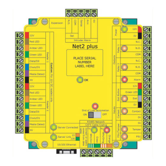
Wiring
The Net2 plus ACU has 2 reader ports and 3
output relays, but can control just one door.
The configuration of one control unit per door
greatly simplifies installation and is ultimately
highly cost effective.
Reader/keypad
12V
LED
LED
1
LED
Data/D0
Clock/D1
Media
Detect
0V
12V
Reader/keypad
LED
(optional)
LED
2
LED
Data/D0
Clock/D1
Media
Detect
0V
Expansion
12V
0V
0V
12V
Set
Set
10
0V
Intruder Alarm
Intruder Alarm
Red LED
N.C.
Net2 plus
Net2 plus
100
Amber LED
N.O.
.
http://paxton.info/107
http://paxton.info/107
Green LED
COM
2345612
2345612
Data/D0
N.C.
123456
LABEL HERE
LABEL HERE
123456
Clock/D1
10/100 Ethernet
N.O.
00-01-02-03-04-05
00-01-02-03-04-05
Media Detect
COM
Alarm
0V
12V
12V
Red LED
Green LED
Amber LED
Exit
0V
Green LED
End of Line Termination
Data/D0
End of Line Termination
Contact
ON
ON
OFF
OFF
Clock/D1
0V
RS485 Network
RS485 Network
0V
Media Detect
CAT5 Cable Coding
CAT5 Cable Coding
Server Connected
Tx
Rx
0V
Tx
Rx
Tamper
10
Server Link
PSU
100
10/100 Ethernet
10/100 Ethernet
LED indications
12/24V
Relay 1
Relay 2
Alarm
Exit
Contact
Tamper
PSU
OK
Termination
Rx
Tx
Server Connected
Server Link
For instructions in alternative languages - http://paxton.info/1000
Intruder alarm
integration
Expansion
12V
Set
Intruder Alarm
Red LED
Amber LED
http://paxton.info/107
Green LED
Data/D0
Clock/D1
Media Detect
0V
12V - 24V
0V
0V
12V
N.C.
Red LED
N.O
1
Amber LED
COM
Green LED
N.C.
Data/D0
N.O
2
COM
Clock/D1
OK
Media Detect
Server Connected
12V
0V
LED
Server Link
EXIT
0V
EXIT
0V
10/100 Ethernet
10/100 Ethernet
I
0V
RS485
0V
Switchable 120 ohm
CAT5
TX
RX
resistors
PSU
from previous ACU
TCP/IP patch lead
(Green)
- Power LED.
(Orange)
- The relay is energised - (NO/COM contacts are closed).
(Orange)
- The relay is energised - (NO/COM contacts are closed).
(Red)
- 12V Alarm output is active.
(Orange)
- The exit button contacts are closed.
(Orange)
- The door contacts are closed.
(Orange)
- The tamper contacts are closed.
(Orange)
- The PSU contacts are closed.
(Green flash)
- The internal software is running.
(Red)
- The on-board resistors are in place across the RS485 data pairs.
(Red)
- The ACU is receiving data (TCP/IP or RS485) - See also FAQ section.
(Green)
- The ACU is responding to data - (TCP/IP or RS485).
(Green)
- The TCP/IP interface is communicating with the PC Net2 server.
- Green = 100 Mbit/s : Orange = 10 Mbit/s (TCP/IP speed).
supportUS@paxton-access.com
Monday - Friday from 02:00 AM - 8:00 PM (EST)
12V
0V
0V
Set
0V
Intruder Alarm
N.C.
Net2 plus
Net2 plus
N.O.
.
http://paxton.info/107
COM
2345612
2345612
N.C.
123456
123456
LABEL HERE
LABEL HERE
N.O.
00-01-02-03-04-05
00-01-02-03-04-05
COM
Alarm
12V
Green LED
Exit
0V
End of Line Termination
End of Line Termination
Contact
OFF
ON
OFF
ON
0V
RS485 Network
RS485 Network
0V
CAT5 Cable Coding
12V
CAT5 Cable Coding
Tx
Rx
Tx
Rx
Tamper
LED
LED
10
PSU
100
LED
Data/D0
Clock/D1
Media
Detect
0V
12V
LED
Tamper switch
LED
LED
Data/D0
Clock/D1
Media
Detect
0V
Door Lock
Exit button (push to make)
12V - 24V
1
1
Normally closed door contact
2
(optional)
OK
12V
Expansion
LED
12V
Red LED
Amber LED
Green LED
EXIT
2
EXIT
Data/D0
Clock/D1
(optional)
Media Detect
0V
12V
Red LED
Amber LED
I
Green LED
Data/D0
Clock/D1
Media Detect
RS485
0V
CAT5
TX
RX
10
100
to next ACU
10/100 Ethernet
For a fail open lock (Maglock), wire 0V to the
"N.C. " terminal instead of "N.O. "
Paxton
12V DC power
supply
0V
0V
N.C.
N.O
COM
N.C.
N.O
COM
12V
0V
0V
Set
Set
0V
Intruder Alarm
Intruder Alarm
N.C.
Net2 plus
Net2 plus
.
N.O.
0V
http://paxton.info/107
http://paxton.info/107
COM
2345612
2345612
N.C.
123456
123456
LABEL HERE
LABEL HERE
N.O.
00-01-02-03-04-05
00-01-02-03-04-05
COM
0V
Alarm
12V
Green LED
Exit
0V
End of Line Termination
End of Line Termination
Contact
0V
OFF
ON
ON
OFF
0V
RS485 Network
RS485 Network
0V
CAT5 Cable Coding
CAT5 Cable Coding
Server Connected
Tx
Tx
Rx
Rx
Tamper
0V
10
Server Link
PSU
100
10/100 Ethernet
10/100 Ethernet
PSU
PAGE 1
Advertisement
Table of Contents

Subscribe to Our Youtube Channel
Related Manuals for Paxton Net2 plus


Summary of Contents for Paxton Net2 plus
- Page 1 Technical help is available: Monday - Friday from 02:00 AM - 8:00 PM (EST) Documentation on all Paxton products can be found on our web site - http://www.paxton-access.com/ For instructions in alternative languages - http://paxton.info/1000 Intruder alarm 12V DC power...
- Page 2 One Net2 plus can also be used as the TCP/IP interface for an RS485 daisy chain of Net2 plus and Net2 classic units. When used with a TCP/IP connection, it must first be detected using the Net2 Server Configuration Utility as defined later in this instruction.
-
Page 3: Cable Type
PC is updated when it comes back on line. PC installation The current specification for compatible PC hardware, network and operating systems is available on our website at the following link: http://paxton.info/720 PAGE 3... - Page 4 Connecting to the PC via the Ethernet port If the TCP/IP data connection is longer than 25 ft the following surge protection device must be installed within 3 ft of the control unit. Data line surge protector. Emerson Network Power: Model LCDP-060. The IP address should be assigned a fixed value, or a DHCP reservation.
- Page 5 Server Control unit RS485 data line resistance check Power down all TCP/IP, USB and RS232 converters (individual and Net2 plus). Check the resistance across each data pair is 60-80 ohms. Check that there are no data line to screen shorts.
-
Page 6: Installation And Test
It is advisable to ensure that any third party backup power supplies or recovery procedures are checked regularly to ensure that the operation of the Paxton system is not compromised. 1 - Short circuiting, mutilation or incineration of the cells must be avoided to prevent one or more of the following occurrences;... -
Page 7: Exit Button
INPUT / OUTPUT WIRING Exit button Where fitted, a 'push to make' button is required. (See Specification table for ratings) The Exit LED will be ON when the switch is closed. - Button Pushed. When the Exit terminal is shorted to 0V, the Exit LED will illuminate and the ACU will operate Relay 1. The reader/exit button Green LED will flash during this period. - Page 8 Alarm sounder This local alarm has a transistor 'open drain' output, (not a dry contact relay) and will switch 1A at 12V DC for a bell, light etc. This local output can be turned on or off for each type of alarm and can be configured to sound continuously or intermittently to distinguish between different alarm types.
-
Page 9: Software Configuration
PROXIMITY panel mount reader Intruder alarm integration A dedicated port for input and output signals is provided when integrating a Net2 plus ACU with an alarm system. Please see AN1035 - Integrating Net2 with an intruder alarm system < http://paxton.info/91 >... -
Page 10: Technical Help
Technical Help 1 - RS485 Data line resistance check - ACU not responding or fails to be detected. QFirst power down any data line converters and disconnect any ACU's that do not have a flashing OK LED. Using a QMultimeter, measure the resistance across the White/Green and Green pair at one end of the network. QA resistance of between 60 and 80 ohms is required. -
Page 11: Fcc Compliance
Product compliance and limitations To comply as a UL listed installation, the following conditions must apply:- The power must be provided via a separate DC supply, a UL Listed Access Control (or Burglar Alarm) Class 2, Power-Limited, power source capable of 4 hours standby must be employed. This is wired into the 0V and 12/24V terminals and the cable secured with the cable ties provided. - Page 12 Options Sales Code Description 682-493-US Net2 plus access control unit 682-528-US Net2 plus ACU in plastic housing Specifications Electrical 12V DC 24V DC (+20%) Voltage 200 mA PCB Current (depending on activity) 24V DC (+20%) Relay switchable voltage Relay switchable current...
Need help?
Do you have a question about the Net2 plus and is the answer not in the manual?
Questions and answers