Table of Contents
Advertisement
Advertisement
Table of Contents

Related Manuals for Nipponia F3


Summary of Contents for Nipponia F3
-
Page 2: Table Of Contents
Contents Page General Instructions before riding Page 3 Inspection points Page 4 Assembly Instructions Page 5 Technical Specifications Page 6 Parts List Page 7 Dashboard Page 8 Display Page 9-11 Diagnostic Trouble code Page 12-13 Ignition Key Page 14 Handlebar Controls Page 15-16 Accelerating &... -
Page 3: General Instructions Before Riding
General Instructions Before Riding 1. To ensure the vehicle is functioning correctly, do a quick check of the vehicle’s tires and make sure that the brakes are working (for more detailed maintenance instructions, see the Maintenance Schedule). Your vehicle has been thoroughly checked by our engineers before delivery, but it is important that you also check it before operation. -
Page 4: Inspection Points
10. Driving frequently at an economical speed will help extend the battery range and life cycle, especially with crowded city traffic. Inspection points before every use Item Action Front Brake (Right Squeeze the right-hand brake lever and push the lever only controls vehicle forward to see whether it rolls easily. -
Page 5: Assembly Instructions
Assembly Instructions Installing the mirrors Mirrors can be easily attached to the handlebars between the grips and the brake lever. Screw in the mirror clockwise. The mirror that goes on the left controller is curved to the left and the mirror that goes on the right controller is curved to the right. -
Page 6: Technical Specifications
Technical Specifications F3 TECHNICAL DATA rear wheel side motor Motor (W) 72V 2000W Battery (V)(AH) Li-ion 72V/16Ah x2 Communication System CANbus speed range Speed 45KM/h 92KM E-mark certificate No. e13*168/2013*00689*00 Category L1e-B Charger Input Voltage 110V-230V Charger 84V 10A Charging Time 3.5 hours... -
Page 7: Parts List
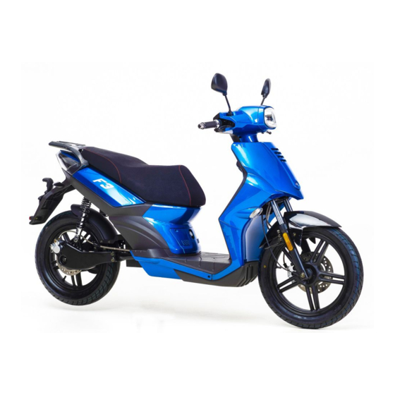
Parts List A. Headlight B. Rear View Mirror C. Throttle and Brake Lever D. Front Indicator E. Front Shock Absorber F. Front Tire G. Seat H. Side Stand I. Centre Stand J. Rear Side Motor K. Rear Tire L. Rear Reflector M. -
Page 8: Dashboard
T. Taillight Dashboard Part Item Function Left Indicator Light flashes green when indicator is on Right Indicator Light flashes green when indicator is on High beam Indicates high beam activation light Lights in amber and indicates an error with the CANbus function Battery SOC Total 10 segment indication Three mode... -
Page 9: Display
DISPLAY 1. Battery SOC: the battery SOC% is controlled by CANbus communication. LCD display SOC (%) via CANbus ~ segment displayed ~ segment displayed ~ segment displayed ~ segment displayed ~ segment displayed ~ segment displayed ~ segment displayed ~ segment displayed ~... - Page 10 2.2 Adjusting screen rear light brightness: Press Reset to adjust the brightness of the rear light in 4 increments (100%->75%->50%->25%->100%) 2.3 Press Reset and Select for 3 sec simultaneously to switch to the metric system 2.4 LCD characteristics: 1. Operating temperature: -30 °C ~ +80 °C 2.
- Page 11 (When entering 0~20% SOC via CANbus) 5. BATTERY CANbus (0×A0A0): "Charging condition" [Byte1 BIT 0] When this data is shown, do not engage MCU CANbus signal error “C10”...
-
Page 12: Diagnostic Trouble Code
6. Diagnostic Trouble Code (DTC) 6-1. BATTERY (ID: 0x0000A0A1,0x0000A1A1) DTC Express CANbus on the display Message Description Battery Battery Byte Bit No data BMS CANbus Signal Failure Charging voltage is too high Charging with too high current Discharging voltage is too low Discharging with too high current Short circuit... - Page 13 6-2. MCU (ID: 0x00000101) CANbus DTC Express Message Description on the display Byte No data MCU CANbus Signal Failure Identification Error Voltage too high Low voltage Motor did not start Internal voltage error Overheated Throttle error at power-up Internal reset Throttle open or short Motor Overheated Hall galvanometer sensor error...
-
Page 14: Ignition Key
Ignition Key Key Position Description Key cannot be removed while the power is on. Key can be removed when the power is off Handlebar lock To prevent theft always lock the steering when parked. Turn the handlebar all the way to the left and turn the key to the locked position. -
Page 15: Handlebar Controls
Left handlebar controls High Beam – Push switch up Headlight Switch Low Beam – Push switch down Left Turn Indicator – Slide switch to the left Right Turn Indicator – Slide switch to the right Indicator Switch Cancelling Indicator– Press the central release button To sound horn –... - Page 16 Right handlebar controls When the right brake lever is engaged the Right Brake Lever front brake will activate. To engage, turn the throttle clockwise. Turn throttle counterclockwise to increase Throttle speed. 1. Slide switch to the left, front and rear light turn on.
-
Page 17: Accelerating & Braking
Accelerating and Braking Throttle Tips Turn the key to the ‘ON’ position and press the start button. You will hear a beeping sound and the brand name will appear on dashboard. You can then start driving the scooter. To prevent losing control of the vehicle, twist the throttle slowly for the speed to increase. -
Page 18: Battery & Charging Instructions
Battery and Charging Instructions Battery Description display While riding, when the battery is fully charged, the 10 segments dashboard displays 10 segments. When the dashboard shows 2 segments, that means there is not much power left in the battery. Drive at 2 segments reduced speed to extend the range and find the nearest charging point. -
Page 19: Performance
Battery Longevity The driver should, if possible, charge the battery after every trip as this will help to improve the battery life. The life of the Li-ion battery is 1200 deep cycles (80% deep discharged), but if you do not charge the battery frequently or when the battery level drops below 50%, the battery life will decrease. -
Page 20: Maintenance
Maintenance This electric motorcycle represents generation environmentally friendly two-wheeled transportation. Good maintenance will therefore play a major role in keeping your vehicle in good working condition and prolonging the life of the battery. Please follow these suggestions: • To prevent rust, always keep your vehicle dry and clean. •... -
Page 21: Maintenance Schedule
Maintenance Schedule Mileage km Every Every Every Every 1000 2000 6000 10000 Battery Charger Tire Pressure Tire Wear Brake System Brake Pad Nuts and Bolts A: Adjust C: Check T: Tighten... -
Page 22: Frequently Asked Questions
5. Q. What about parts, is it difficult to get parts for the F3 model? A. All parts are available and can be purchased from the local dealer, including batteries, tires, lightbulbs, bodyshells, seats, etc. - Page 23 A. Due to its waterproof wiring bundle, Direct Current source and 72V system design, there is no risk involved when the vehicle gets wet. However, be careful not to pour water directly into the charger outlet, the controller and the internal battery set when washing or cleaning.
- Page 24 A. Riders will not get burned from riding the electric vehicle. The vehicle does not have an exhaust pipe like in gasoline scooters. No parts heat up. 13. Q. Why is this product the best available in the world today? It has a brushless motor.
-
Page 25: Troubleshooting
Troubleshooting Problem Condition Check Solution Check if the DC- 1. Light off, DC input and Change the DC-DC horn off, output voltage is convertor, secure press start correct. Check if the plugs, or button, the plug is change the fuse. throttle, motor secured. -
Page 26: Circuit Diagram
Circuit Diagram... -
Page 27: Service Plan
SERVICE PLAN The Warranty can be granted only if the vehicle has been serviced in accordance with this service plan. 400 km 2000 km Stamp / Signature Stamp / Signature 4000 km 6000 km Stamp / Signature Stamp / Signature VEHICLE IDENTIFICATION NUMBER: ............................................................ - Page 28 SERVICE PLAN The Warranty can be granted only if the vehicle has been serviced in accordance with this service plan. 8000 km 10000 km Stamp / Signature Stamp / Signature 12000 km 14000 km Stamp / Signature Stamp / Signature VEHICLE IDENTIFICATION NUMBER: ............................................................
- Page 29 SPACE FOR NOTES...
- Page 30 NIPPONIA S.A. EUROPEAN DISTRIBUTION CENTER a: 12, Agias Fotinis str. TRADE & TRAFFIC PLUS B.V. Nea Smyrni, 17121 Athens, Greece a: Prins Mauritslaan 5a, 8091 AJ e: hq@nipponia.com Wezep, Netherland p: +30 210 9328800 e: info@trade-traffic.com w: www.nipponia.com p: +31 (0) 38-4533222 w: www.trade-traffic.com...
Need help?
Do you have a question about the F3 and is the answer not in the manual?
Questions and answers