
Related Manuals for WEG MMW03-CH


Summary of Contents for WEG MMW03-CH
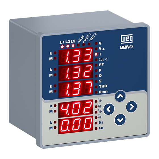
- Page 1 Motors | Automation | Energy | Transmission & Distribution | Coatings Electronic Multimeter MMW03-CH User Manual...
- Page 3 User Manual Series: MMW03-CH Language: English Document: 10006614873 / 00...
-
Page 5: Table Of Contents
1 GENERAL INFORMATION 1.1 DEVICE FEATURES AND MODEL SELECTION ..................6 1.2 CORRECT USAGE AND CONDITIONS FOR SAFETY ................6 1.3 PANEL DEFINITIONS ..........................7 1.3.1 MMW03-CH Definitions ......................7 1.4 MENU STRUCTURE ..........................8 1.5 FOUR QUADRANT REPRESENTATION ....................9 2 INSTALLATION 2.1 PREPARING FOR INSTALLATION .....................10 2.2 MOUNTING ............................10... -
Page 6: General Information
1 GENERAL INFORMATION 1.1 DEVICE FEATURES AND MODEL SELECTION MMW03-CH is designed to measure current, voltage, harmonic ete. in 3 phase system. The model and their features are shown in below table. MMW03-CH Type of device enclosure Panel Basic measurements —... -
Page 7: Panel Definitions
Left arrow key. Use this key to switch between the menus, return to the upper menu – level and confirm the selected value. Down arrow key. Use this key to switch between the menus and change – the numerical values. Electronic Multimeter - MMW03-CH | 7... -
Page 8: Menu Structure
Apparent Power Maksimum Minimum Demand THDV THDV THDV … Maximum Minimum THDI THDI THDI … Maximum Minimum Energy Meters … … … Counters … … … Setting … … … Tabela 1.2: Menu Structure 8 | Electronic Multimeter - MMW03-CH... -
Page 9: Four Quadrant Representation
Note: If the signs of active and reactive power are examined, it can be defined the quadrant that MMW03 measures. In order to understand P and Q signs in MMW03-CH, instantaneous displays for P and Q must be checked. If active power display is seem constantly, it means active power(P) is positive. If it is blinked, it means active power(P) is negative. -
Page 10: Installation
2.2 MOUNTING MMW03-CH is placed vertically into the gap located in the panel. After the product is placed into the panel, fixing brackets should be installed on the product. After that it should be fixed to the panel wall with the screws. -
Page 11: Dimensions (Mm)
– Any/All of L1, L2, L3 LED(s) blink(s) quickly (per 0.2 second) current connection(s) of the related phase(s) is/are missing. 2.4 DIMENSIONS (MM) Figura 2.2: Dimensions for MMW03-CH Electronic Multimeter - MMW03-CH | 11... -
Page 12: Menus
„ Line-2 phase-neutral voltage is monitored in the second display. „ Line-3 phase-neutral voltage is monitored in the third display. „ Average phase-neutral voltage of three phase is monitored in fourth display. „ Network frequency is monitored in fifth display. 12 | Electronic Multimeter - MMW03-CH... -
Page 13: Maximum, Minimum Ve Demand Menus
Total Current Min. Min. Current L1 Current L2 Current L3 Total Current Demand Demand Demand Demand Cos φ1 Max. Cos φ2 Max. Cos φ2 Max. Cos φ Cos φ1 Min. Cos φ2 Min. Cos φ2 Min. Electronic Multimeter - MMW03-CH | 13... - Page 14 - maximum value of the related parameter will be “0” in maximum page of “L-H Menu”. - in minimum page of “L-H Menu; “k LED” and “M LED” belonging to current/voltage will turn on continuously. Operator will monitor the number “888” in the related 7 segment display. 14 | Electronic Multimeter - MMW03-CH...
-
Page 15: Energy Meters Menu (Enr)
Enter the password to proceed to the counter assignment. 3.4 SETTINGS MENU (SEt) MMW03-CH setings is made in the SEt menu. Table 3-3 shows the Set menu tree. ATTENTION! The menu tree is based on the fully equipped variant model. Some of the menus may be missing in less equipped models. - Page 16 Timeout for password protection. If you do press any Pın keys after entering the password or do not change any settings via MODBUS, password protection is re-enabled after the time has elapsed. Change password 16 | Electronic Multimeter - MMW03-CH...
-
Page 17: Basic Settings Menu (Bsc)
(Phase-Neutral)”. This menu is displayed first when the device is energized. If “dEL” (3-phase, 3-wire connection type) was specified for the network connection setup, the initial menu is “Voltage (Phase-Phase)”. This menu is displayed first when the device is energized. Electronic Multimeter - MMW03-CH | 17... -
Page 18: Alarm Settings Menu (Alr)
“password activation time” has elapsed. You can set this value in the respective menu item. Please see Table 3-3 for the menu tree and Section 5 for the factory default settings. 18 | Electronic Multimeter - MMW03-CH... -
Page 19: Rs485 Settings Menu (485)
Use the up/down keys to increase/decrease the value of the active digit. Set the desired values for variables by setting the individual digit values and press the left key to complete your action. Electronic Multimeter - MMW03-CH | 19... -
Page 20: Saving
Then, press the left key to store the changes. To discard the changes: Press the right key to blink the “nO” sign. Then exit the menu using the left key without saving your changes. 20 | Electronic Multimeter - MMW03-CH... -
Page 21: Rs485 Communication
4 RS485 COMMUNICATION MMW03-CH model support RS485 communication. Please see Table 3-3 for the menu tree. 4.1 READABLE AND WRITABLE DATA The following functions are supported: „ Function 03H: This function reads the readable addresses in the modbus table. - Page 22 Phase 2 Current Harmonics 7 float Phase 2 Current Harmonics 9 float Phase 2 Current Harmonics 11 float Phase 2 Current Harmonics 13 float Phase 2 Current Harmonics 15 float Phase 2 Current Harmonics 17 float 22 | Electronic Multimeter - MMW03-CH...
- Page 23 Phase 2 Max. Cosφ Phase 2 Max. Power Factor float Phase 2 Max. Active Power float Phase 2 Max. Reactive Power float Phase 2 Max. Apparent Power float Phase 2 Max. THDV float Electronic Multimeter - MMW03-CH | 23...
- Page 24 Minimum Common Measurements (Phase-1, Phase-2, Phase-3) Min. Average Voltage (L-N) float Min. Average Voltage (L-L) float Min. Total Current float Min. System Power Factor float Min. Total Active Power float Min. Total Reactive Power float 24 | Electronic Multimeter - MMW03-CH...
- Page 25 Import Reactive Energy T2-Phase1 (Tariff 2) 32 bit integer R / W Change” field. You can then enter the value. Export Reactive Energy T2-Phase1 (Tariff 2) 32 bit integer R / W Tariff 2 Phase 2 Energy Values Electronic Multimeter - MMW03-CH | 25...
- Page 26 Cosφ Alarm Low Limit float R / W float R / W Cosφ Alarm Hysteresis Cosφ Alarm Delay Time 32 bit integer R / W Power Factor Alarm High Limit float R / W 26 | Electronic Multimeter - MMW03-CH...
-
Page 27: Alarm Flags
I3 OFF I2 OFF I1 OFF V3 OFF Status Status Status Status Status Status Freq Freq Cosφ Cosφ I(N) I(N) V(L-L) V(L-L) V(L-N) V(L-N) V2 OFF V1 OFF High High High High High High High Tabela 4.2: Alarm Flags Electronic Multimeter - MMW03-CH | 27... -
Page 28: Multiple Choice Settings Via Modbus
Relay 1 run. Function Digital Input 2 Edge Relay 2 Function Password Enable 1200 baud 2400 baud Pulse Output 1 4800 baud Parameter Baud Rate 9600 baud 19200 baud 38400 baud 57600 baud Parity Control 28 | Electronic Multimeter - MMW03-CH... - Page 29 Parity Control Digital Input 1 Type Pulse Output 2 run. Parameter Digital Input 1 Edge Tabela 4.3: Description List Electronic Multimeter - MMW03-CH | 29...
-
Page 30: Factory Default Settings
Relay 1 setup OFF/HI/LO Relay 2 setup OFF/HI/LO Demand time setup 1 - 60 Enable/disable NO/YES password protection Pın Timeout for 1 - 60 password protection Change password 1 - 9999 30 | Electronic Multimeter - MMW03-CH... - Page 31 Pulse output 2 OFF/IA1/EA1/Ir1/Er1/ parameter setup IA2/EA2/Ir2/Er2/dI1/dI2 Pulse duration of the msec 50 - 2500 pulse output 2 kWh/ Step range for pulse kVARh/ 1 - 999 999 999 output 2 OFF/All/Enr/Cnt/HI/LO/ Clear menu dEd/SEt/ ALr Electronic Multimeter - MMW03-CH | 31...
- Page 32 ≤ I ≤ I (calculated) Voltage ≤ U ≤ U Power factor 0,5 Ind to 0,8 Cap Total harmonic THDV 0 % to 20 % distortion voltage Total harmonic THDI 0 % to 100 % distortion current 32 | Electronic Multimeter - MMW03-CH...
- Page 33 NOTES Electronic Multimeter - MMW03-CH | 33...
- Page 34 NOTES 34 | Electronic Multimeter - MMW03-CH...
- Page 35 NOTES Electronic Multimeter - MMW03-CH | 35...
- Page 36 Phone: +39 2 61293535 Phone: +86 519 88067692 info-it@weg.net info-cn@weg.net For those countries where there is not a WEG own operation, find our local distributor at www.weg.net. WEG Group - Automation Business Unit Jaraguá do Sul - SC - Brazil Phone +55 47 3276 4000 automacao@weg.net...
Need help?
Do you have a question about the MMW03-CH and is the answer not in the manual?
Questions and answers