Advertisement
Quick Links
Advertisement

Related Manuals for WEG MMW03-CH


Summary of Contents for WEG MMW03-CH
- Page 1 MMW03-CH Multimeter...
- Page 2 MMW03-CH - Multimeter Designed to measure: Phase-Neutral Voltage; Phase-Phase Voltage; ➢ Phase Current; Neutral Current; ➢ Frequency; ➢ ⱷ ; Power factor; ➢ Active power; Reactive power; Apparent power; ➢ THDv, THDi, ➢ Voltage and current harmonics up to the 31 order (over ➢...
- Page 3 MMW03-CH - Multimeter Other functions: Indication of phase loss and phase sequence error ➢ It determines and saves, in the memory, the maximum and ➢ minimum values of: Voltage; ✓ Current; ✓ Frequency; ✓ cosφ and power factor; ✓ THDv; THDi;...
- Page 4 MMW03-CH - Multimeter Other functions: Current, voltage, frequency, cosφ and power factor alarms ➢ Stores: ➢ Hour meter; ✓ Total time energized; ✓ Total time de-energized; ✓ RS485 communication with MODBUS RTU protocol; ➢ 2 alarm output relays; ➢ 4-digit password;...
-
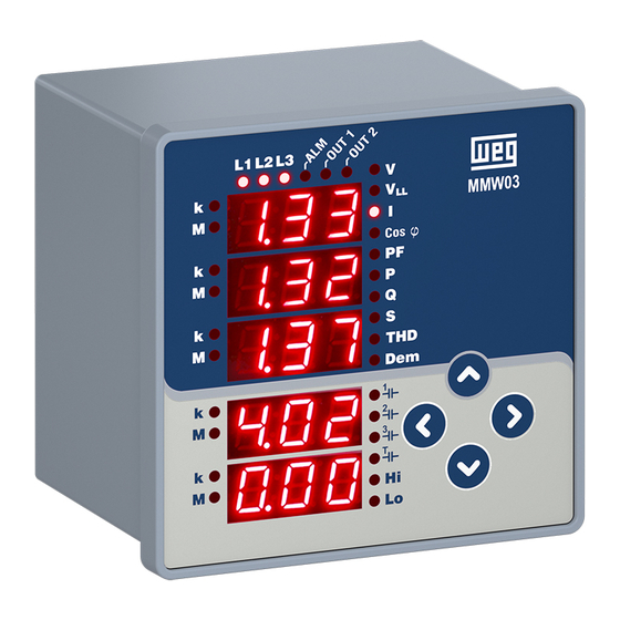
Page 5: Front Panel
Front panel Output relays and alarm; Phases Kilo and Mega Instant measurement indicators Capacitive indication per phase and of the system Indicators (7 segments) Arrow keys Maximum or minimum value indicator... - Page 6 MMW03-CH Menus...
- Page 7 Indicators L1, L2 and L3 L1, L2, L3 flashing simultaneously and very slowly (1 per second): • Error in the phase sequence - voltage; None/all of L1, L2, L3 flashing slowly (1 for 0.5 second): • Voltage loss in one or all connections None/all of L1, L2, L3 flashing slowly (1 for 0.2 second): •...
-
Page 8: Measurement Menus
Measurement menus... - Page 9 Measurement menus V F-N Phase-Neutral Reading (F-N) Phase 1 - F-N Voltage Phase 2 - F-N Voltage Phase 3 - F-N Voltage F-N average voltage Line frequency...
- Page 10 Measurement menus V F-F...
- Page 11 Measurement menus I (current)
- Page 12 Measurement menus Cosφ...
- Page 13 Measurement menus PF (Power factor)
- Page 14 Measurement menus P Active power...
- Page 15 Measurement menus Q Reactive power...
- Page 16 Measurement menus S Apparent power...
- Page 17 Measurement menus THDv...
- Page 18 Measurement menus THDi...
- Page 19 Measurement menus – V (L-N) Maximum and minimum menus The maximum and minimum values are calculated and stored in non-volatile memory for the following parameters ➢ Voltage (F-N and F-F) ➢ Neutral current ➢ Frequency ➢ Cosφ ➢ Power factor ➢...
- Page 20 Measurement menus Demand Menus The demand values are calculated and stored in non- volatile memory for the following parameters: ➢ Current ➢ Active power ➢ Reactive power ➢ Apparent power To view max. and min. and demand menus, use the left and right arrow keys.
- Page 21 Measurement menus If the system consumes energy, (P) must be positive. If the active power display (P1, P2 or P3) is flashing in L-H or instant menu, reverse the input connection of the current transformer (k-l)
- Page 22 Energy measurement menus To access the ENERGY menu, use the UP and DOWN arrow keys Available energy parameters: • Import active energy (I.Ac) • Export active energy (E.Ac) • Import reactive energy (I.rE) • Export reactive energy (E.rE)
- Page 23 Energy measurement menus Preset value: In any menu on the device, press for at least 2 seconds and release. The menu will start flashing. Using the right arrow key, move the indicator to the digit you want to change. Enter the desired value using the up and down arrow keys.
-
Page 24: Meters Menu
Meters menu To navigate to the Meters menu, use the Up and Down arrow keys "On hour" Meter: The display shows the total hours that the equipment was energized. "Run hour" Meter: It shows the time the device performed the measurement. It is necessary that the signal inputs be fed by the three current phases and three voltage phases. - Page 25 Meters menu...
-
Page 26: Settings Menu
Settings menu The settings are done in the SEt menu. To navigate to the settings menu, use the Up and Down arrow keys... - Page 27 Settings menu - basic In this menu, it is defined: • Current transformer ratio - CTR • Voltage transformer ratio - VTR • Connection type - 3P4W (star) or 3P3W (delta) Connectio CTR: 1-5000 BASIC VTR: 1.0-5000.0 CONNECTION: STAR (3P4W), DELTA (3P3W)
- Page 28 Settings menu - Alarm In this menu, the alarm limits, hysteresis and alarm holding time are configured. ALARMS: - U (L-N), ULL (L-L), - I (current), In (I neutral), - COSφ, PF,...
- Page 29 Settings menu - Alarm U (Voltage L-N) Holding time Lower Hysteresis Upper limit limit When the alarm limit is exceeded: • "k" and "M" LEDs of the respective parameter start flashing at the same time. • After the holding time has elapsed, the "ALM" LED turns on; if the alarm relay is programmed to operate, OUT1 and/or OUT2 LEDs turn on and the respective relay is energized.
- Page 30 Settings menu - Alarm In this menu, the operating conditions of the alarm relays are defined Relay 1/2: OFF, LO, HI The alarm relays can be programmed to: • OFF : Relay is not energized in an alarm condition • LO : Relay is activated when the lower limit alarm is triggered •...
- Page 31 Settings menu - Demand In this menu, the demand time conditions are defined. After defining the period, which may be from 1 to 60 minutes, the demand values are calculated periodically considering this time.
- Page 32 Settings menu - Password In this menu, it is defined: - Activate the password or not; - Define password; - Password activation time; Activation Pin Time Change Act - Activation: Enable/Disable password protection (NO/YES) P t - Pin Time: Time to request password again. When any key is pressed after entering the password or no change is made via MODBUS, the password protection is activated after the preset time has elapsed (1-60min)
- Page 33 Settings menu - RS485 In this menu, the MODBUS RTU, RS485 communication parameters are defined: - Baud Rate - Network communication rate; - Slave ID; - Parity control Baud Rate Parity Baud Rate: Options of (1200/2400/4800/9600/19200/38400/57600) Slave ID of (1-247) Parity: Parity check definition (None, Even, Odd)
- Page 34 Settings menu - Clear In this menu, the values stored in the machine's memory are deleted and the factory values are restored. • OFF : Disable the "clear" process • All : Clear all stored values and restores factory settings •...
- Page 35 Settings menu - Version This menu shows the device firmware version...
- Page 36 SAVE procedure Press the left arrow key up to the "SAU" screen. Press the key until "YES" or "NO" is shown to confirm the changes in the settings or not. To confirm the changes: Press the right button until "YES" flashes. Then press the left arrow key to save the changes.
-
Page 37: Technical Specifications
Technical specifications... - Page 38 Measurements - accuracy...
- Page 39 WEG Drives & Controls Thank you!
Need help?
Do you have a question about the MMW03-CH and is the answer not in the manual?
Questions and answers
o multimedidor Liga mais so aprece zeros
The WEG MMW03-CH multimeter may display only zeros due to one or more of the following reasons:
1. Voltage or Current Loss: If there is voltage or current loss in one or all connections, the device may not detect any input, resulting in zero readings. This is indicated by slow flashing of L1, L2, and L3 indicators.
2. Phase Sequence Error: A phase sequence error can prevent correct measurement, also leading to zero display. This is indicated when L1, L2, and L3 flash simultaneously and very slowly.
3. Incorrect or Incomplete Electrical Installation: If the device is not correctly wired or connections are incomplete, it may not measure input values, showing zeros.
4. Device Not Properly Configured or Activated: If the device is not correctly configured or not activated after installation, it may not function as expected.
To resolve the issue, verify all connections, check for voltage and current presence, ensure correct phase sequence, and confirm proper device setup.
This answer is automatically generated