Table of Contents
Advertisement
Advertisement
Chapters
Table of Contents

Related Manuals for Juniper SRX380


Summary of Contents for Juniper SRX380
- Page 1 SRX380 Services Gateway Hardware Guide Published 2020-03-31...
- Page 2 END USER LICENSE AGREEMENT The Juniper Networks product that is the subject of this technical documentation consists of (or is intended for use with) Juniper Networks software. Use of such software is subject to the terms and conditions of the End User License Agreement (“EULA”) posted at https://support.juniper.net/support/eula/.
-
Page 3: Table Of Contents
SRX380 Cooling System | 23 SRX380 Power System | 23 SRX380 Services Gateway Power Supply | 24 AC Power Supply LEDs on SRX380 Services Gateways | 25 Power Specifications for SRX380 Services Gateways | 25 AC Power Cord Specifications for SRX380 | 26... - Page 4 Connecting the SRX380 to External Devices | 47 Connecting an SRX380 to a Network for Out-of-Band Management | 47 Connecting an SRX380 to a Management Console by Using an RJ-45 Connector | 48 Connecting an SRX380 to a Management Console by Using the Mini-USB Type-B Console...
- Page 5 Locating the Chassis Serial Number | 70 Locating the Mini-PIM Serial Number Label | 71 Listing the SRX380 Services Gateway Component Details by Using the CLI | 71 Required Tools and Parts for Packing the SRX Series Services Gateway | 72...
- Page 6 Action to Take After an Electrical Accident | 100 General Electrical Safety Guidelines and Warnings | 100 AC Power Electrical Safety Guidelines | 101 SRX380 Services Gateway Agency Approvals | 102 SRX380 Services Gateway EMC Requirements | 104 Canada | 104...
-
Page 7: About The Documentation
Use this guide to install hardware and perform initial software configuration, routine maintenance, and troubleshooting for the SRX380 Services Gateway. After completing the installation and basic configuration procedures covered in this guide, refer to the Junos OS documentation for information about further software configuration. -
Page 8: Merging A Full Example
viii If the example configuration contains the top level of the hierarchy (or multiple hierarchies), the example is a full example. In this case, use the load merge command. If the example configuration does not start at the top level of the hierarchy, the example is a snippet. In this case, use the load merge relative command. -
Page 9: Merging A Snippet
Merging a Snippet To merge a snippet, follow these steps: 1. From the HTML or PDF version of the manual, copy a configuration snippet into a text file, save the file with a name, and copy the file to a directory on your routing platform. For example, copy the following snippet to a file and name the file ex-script-snippet.conf. - Page 10 Table 1: Notice Icons Icon Meaning Description Informational note Indicates important features or instructions. Caution Indicates a situation that might result in loss of data or hardware damage. Warning Alerts you to the risk of personal injury or death. Laser warning Alerts you to the risk of personal injury from a laser.
- Page 11 Table 2: Text and Syntax Conventions (continued) Convention Description Examples Italic text like this Represents variables (options for Configure the machine’s domain which you substitute a value) in name: commands or configuration [edit] statements. root@# set system domain-name domain-name Text like this Represents names of configuration To configure a stub area, include statements, commands, files, and...
-
Page 12: Documentation Feedback
URL or page number, and software version (if applicable). Requesting Technical Support Technical product support is available through the Juniper Networks Technical Assistance Center (JTAC). If you are a customer with an active Juniper Care or Partner Support Services support contract, or are... -
Page 13: Self-Help Online Tools And Resources
JTAC hours of operation—The JTAC centers have resources available 24 hours a day, 7 days a week, 365 days a year. Self-Help Online Tools and Resources For quick and easy problem resolution, Juniper Networks has designed an online self-service portal called the Customer Support Center (CSC) that provides you with the following features: Find CSC offerings: https://www.juniper.net/customers/support/... -
Page 14: Overview
C HAPTER Overview SRX380 Services Gateway Overview | 15 SRX380 Chassis | 17 SRX380 Cooling System | 23 SRX380 Power System | 23... -
Page 15: Srx380 Services Gateway Overview
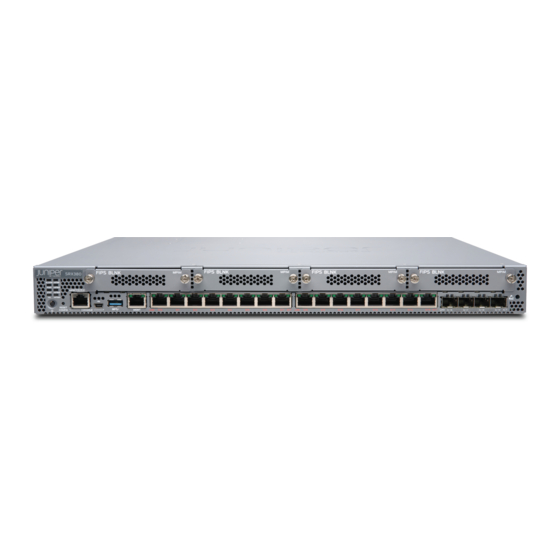
(NGFW) deployments. The SRX380 is designed for enterprise (large branch offices, small campus, SD-WAN) and service provider (managed WAN CPE, SD-WAN) deployments. The SRX380 Services Gateway is 1 rack unit (U) tall and provides high port density with 16 on-board PoE-enabled 1-Gigabit Ethernet ports and 4 10-Gigabit Ethernet ports that support small form-factor pluggable plus (SFP+) transceivers. -
Page 16: Srx380 Services Gateway Frus
You can manage the SRX380 Services Gateway by using the same interfaces that you use for managing other devices that run Junos OS—the CLI, the J-Web graphical interface, and Junos Space. The first supported version of Junos OS for the SRX380 Services Gateway is Release 20.1R1. -
Page 17: Srx380 Chassis
SRX380 Front Panel | 17 SRX380 Back Panel | 21 SRX380 Interface Modules Overview | 22 The SRX380 Services Gateway chassis is a rigid sheet metal structure that houses all of the other components. SRX380 Chassis Overview The SRX380 chassis installs in standard 800–mm (or larger) enclosed cabinets, 19-in. equipment racks, or telecommunications open-frame racks. - Page 18 0 / 13 0 / 14 0 / 15 0 / 16 0 / 17 0 / 18 0 / 19 Table 3: SRX380 Services Gateway Front Panel Components Callout Component Description LEDs Indicate component and system status. Reset Config button Returns the services gateway to the rescue configuration or the factory-default configuration.
-
Page 19: Chassis Status Leds
Power button Use the Power button to shut down the services gateway. NOTE: The SRX380 ships with tamperproof labels for the Mini-PIM slots and SSD slots. Chassis Status LEDs Figure 3 on page 20 shows the LEDs on the front panel of the SRX380. -
Page 20: Management Port And Network Port Leds
Figure 3: SRX380 Services Gateway Front Panel LEDs Table 4 on page 20 lists the front panel LEDs. Table 4: SRX380 Services Gateway Front Panel LEDs Component Description ALARM Solid amber (noncritical alarm) Solid red (critical alarm) Off (no alarms) -
Page 21: Srx380 Back Panel
Figure 4: SRX380 Management Port and Network Port LEDs Table 5: Management Port and Network Port LEDs Callout Description Link Solid green—There is link activity. Off—There is no link established. Activity Blinking green—There is activity on the link. Off—There is no link established. -
Page 22: Srx380 Interface Modules Overview
SRX300 line of services gateways. You can easily insert or remove Mini-PIMs from the front slots of the SRX380 chassis. The Mini-PIMs provide physical connections to a LAN or WAN. The Mini-PIMs receive incoming packets from the network and transmit outgoing packets to the network. During this process, they perform framing and line-speed signaling for the medium type. -
Page 23: Srx380 Cooling System
SRX380 Cooling System The cooling system for the SRX380 Services Gateway includes three fixed fans. The fans draw air through vents on the front of the chassis and exhaust the air through the back of the chassis. The airflow produced by the fans keeps the device components within the acceptable temperature range. -
Page 24: Srx380 Services Gateway Power Supply
SRX380 Services Gateway Power Supply You can install two power supplies in the slots located at the rear of the chassis. Each power supply provides an output power of 600 W. The SRX380 ships with one power supply installed. Figure 7 on page 24 shows the power supply for the SRX380. -
Page 25: Ac Power Supply Leds On Srx380 Services Gateways
Each power supply has two LEDs on the faceplate that indicate the status of the power supply. Table 8 on page 25 describes the AC power supply LEDs. Table 8: AC Power Supply LEDs on the SRX380 Services Gateway Color Description AC OK No AC power input. -
Page 26: Ac Power Cord Specifications For Srx380
AC Power Cord Specifications for SRX380 A detachable AC power cord is supplied with the AC power supplies. The coupler is type C13 as described by International Electrotechnical Commission (IEC) standard 60320. The plug at the male end of the power cord fits into the power source outlet that is standard for your geographical location. - Page 27 Table 10: AC Power Cord Specifications (continued) Country/Region Electrical Specifications Plug Standards Juniper Model Number Korea 250 VAC, 10 A, 50 Hz or 60 CEE (7) VII Type VIIGK CBL-EX-PWR-C13-KR North America 125 VAC, 13 A, 60 Hz NEMA 5-15 Type N5-15...
-
Page 28: Site Planning, Preparation, And Specifications
C HAPTER Site Planning, Preparation, and Specifications SRX380 Site Preparation Checklist | 29 SRX380 Site Guidelines and Requirements | 30... -
Page 29: Srx380 Site Preparation Checklist
Table 11 on page 29 provides a checklist of the tasks you need to perform when preparing a site for installing the SRX380 Services Gateway. Table 11: Site Preparation Checklist for SRX380 Services Gateway Installation Item or Task Additional Information... -
Page 30: Srx380 Site Guidelines And Requirements
SRX380 Services Gateway Environmental Specifications | 31 SRX380 Services Gateway Electrical Wiring Guidelines | 32 SRX380 Services Gateway Physical Specifications | 33 SRX380 Services Gateway Clearance Requirements for Airflow and Hardware Maintenance | 33 Rack Requirements | 34 Cabinet Requirements | 35... -
Page 31: General Site Installation Guidelines For The Srx380 Services Gateway
General Site Installation Guidelines for the SRX380 Services Gateway The following precautions help you plan an acceptable operating environment for your SRX380 Services Gateway and avoid environmentally caused equipment failures: For the cooling system to function properly, the airflow around the chassis must be unrestricted. Allow sufficient clearance between the front and back of the chassis and adjacent equipment. -
Page 32: Srx380 Services Gateway Electrical Wiring Guidelines
SRX380 at your site. CAUTION: It is particularly important to provide a properly grounded and shielded environment and to use electrical surge-suppression devices. Table 13: Site Electrical Wiring Guidelines for the SRX380 Services Gateway Site Wiring Factor Guideline Signaling Limitations To ensure that signaling functions optimally: Install wires correctly. -
Page 33: Srx380 Services Gateway Physical Specifications
SRX380 Services Gateway Clearance Requirements for Airflow and Hardware Maintenance When planning the installation site for the SRX380 Services Gateway, you must allow sufficient clearance around the device. Consider the following requirements: For the operating temperature of the services gateway to be optimal, the airflow around the chassis must be unrestricted. -
Page 34: Rack Requirements
For information on the airflow through the SRX380 Services Gateway chassis, see “SRX380 Cooling System” on page Rack Requirements The SRX380 Services Gateway is designed to be installed on four-post racks. Table 15 on page 34 provides the rack requirements and specifications for the SRX380. -
Page 35: Cabinet Requirements
Cabinet Requirements You can mount the SRX380 in an enclosure or cabinet that contains a four-post 19-in. open rack as defined in Cabinets, Racks, Panels, and Associated Equipment (document number EIA-310-D) published by the Electronics Industry Association. Table 16 on page 35 provides the cabinet requirements and specifications for the SRX380. -
Page 36: Initial Installation And Configuration
C HAPTER Initial Installation and Configuration Unpacking and Mounting the SRX380 | 37 Connecting the SRX380 to Power | 42 Connecting the SRX380 to External Devices | 47 Configuring Junos OS on the SRX380 | 50... -
Page 37: Unpacking And Mounting The Srx380
Mounting the SRX380 Services Gateway in a Rack | 39 Unpacking the SRX380 Services Gateway The SRX380 Services Gateway is shipped in a cardboard carton and secured with foam packing material. The carton also contains an accessory box and quick start instructions. -
Page 38: Verifying Parts Received With The Srx380 Services Gateway
The parts shipped depend on the configuration you order. If any part on the packing list is missing, contact your customer service representative or contact Juniper customer care from within the U.S. or Canada by telephone at 1-888-314-5822. For international-dial or direct-dial options in countries without toll-free numbers, see https://www.juniper.net/support/requesting-support.html. -
Page 39: Mounting The Srx380 Services Gateway In A Rack
Mounting the SRX380 Services Gateway in a Rack You can mount the SRX380 on four posts of a 19-in. rack or cabinet by using the four-post rack-mount kit that is shipped with the device. (The remainder of this topic uses rack to mean rack or cabinet.) - Page 40 To mount the device on four posts of a rack: 1. Remove the device from the shipping carton (see “Unpacking the SRX380 Services Gateway” on page 37). 2. Place the device on a flat, stable surface.
- Page 41 Figure 11: Securing the Device to the Rack 9. Continue to support the SRX380 while sliding the mounting blades into the channel of the mounting rails and securing the blades to the rack. Use four mounting screws (and cage nuts and washers if the rack requires them) to attach the blade to the rack.
-
Page 42: Connecting The Srx380 To Power
Before you begin connecting a device to earth ground, ensure that you have the parts and tools required for your device. Table 19: Parts and Tools Required for Connecting an SRX380 to Earth Ground Grounding Cable Grounding Lug... - Page 43 4. Remove the two screws on the chassis using a Phillips screwdriver. 5. Place the grounding cable lug attached to the grounding cable over the grounding point on the rear of the chassis. Figure 13: Connecting the Grounding Cable to the SRX380 Services Gateway...
-
Page 44: Connecting The Srx380 Services Gateway To An Ac Power Supply
NOTE: The device should be permanently connected to ground during operation. Connecting the SRX380 Services Gateway to an AC Power Supply Ensure that you have the following parts and tools available: A power cord appropriate for your geographical location... -
Page 45: Powering Off The Srx380 Services Gateway
STAT and PWR LEDs—to show that the power supply is functioning normally. Ignore error indicators that appear during the first 60 seconds. Powering Off the SRX380 Services Gateway You can power off the services gateway in one of the following ways: Graceful shutdown—Press and immediately release the Power button. - Page 46 Forced shutdown—Press the Power button and hold it down for 10 seconds. The device immediately powers itself off without shutting down the operating system. CAUTION: Forced shutdown can result in data loss and corruption of the file system. Use the forced shutdown method as a last resort to recover the services gateway if the services gateway operating system is not responding to the graceful shutdown method.
-
Page 47: Connecting The Srx380 To External Devices
Connecting an SRX380 to a Network for Out-of-Band Management You can monitor and manage the SRX380 by using a dedicated management channel. The SRX380 has a management port to which you can connect an Ethernet cable with an RJ-45 connector. Use the management port to connect the device to a network for out-of-band management. -
Page 48: Connecting An Srx380 To A Management Console By Using An Rj-45 Connector
Connecting an SRX380 to a Management Console by Using an RJ-45 Connector The SRX380 has an RJ-45 console port. Use the console port to connect the device to a management console or to a console server. If your laptop or PC does not have a DB-9 male connector pin and you want to connect your laptop or PC directly to the SRX380, use a combination of the RJ-45 cable and RJ-45 to DB-9 adapter supplied with the device and a USB to DB-9 male adapter. -
Page 49: Connecting An Srx380 To A Management Console By Using The Mini-Usb Type-B Console Port
Connecting an SRX380 to a Management Console by Using the Mini-USB Type-B Console Port You can configure and manage the SRX380 by using the RJ-45 console port or the Mini-USB Type-B console port. Only one console port is active at a time. -
Page 50: Configuring Junos Os On The Srx380
Configuring the SRX380 Services Gateway Using CLI | 54 The services gateway is shipped with the Juniper Networks Junos operating system (Junos OS) preinstalled and ready to be configured when the device is powered on. You can perform the initial software... -
Page 51: Plug And Play
The SRX380 already has factory-default settings configured to make it a plug and play device. So all you have to do to get the SRX380 up and running is connect it to your LAN and WAN networks. 1. Connect the WAN network to port 0/0 or 0/19. -
Page 52: Configure The Srx380 Using J-Web
Internet connection. After you complete these steps, you can start using the SRX380 on your network right away. You can go back and customize settings at anytime. The J-Web Setup wizard is always available to you. - Page 53 To modify the configuration using J-Web: 1. In the J-Web application, select Configure > Setup Wizard. The Setup wizard opens on your screen. Figure 18: Setup Wizard Page 2. Select Standard. 3. Configure the device and users: a. Enter the hostname. b.
-
Page 54: Configuring The Srx380 Services Gateway Using Cli
Once you click OK, the Setup Wizard applies your configuration. NOTE: You might lose connectivity to the SRX380 device if you changed the IP address of the port to which the laptop is connected. If you lose connectivity, open a new browser window and type https://<new IP address>... - Page 55 root@% cli root> 4. Enter configuration mode. root> configure [edit] root# 5. Set the root authentication password by entering a cleartext password, an encrypted password, or an SSH public key string (DSA or RSA). [edit] root# set system root-authentication plain-text-password New password: password Retype new password: password 6.
- Page 56 [edit] admin# set system host-name host-name 10. Configure the IP address and prefix length for the services gateway Ethernet interface. [edit] admin# set interfaces fxp0 unit 0 family inet address address/prefix-length 11. Configure the traffic interface. [edit] admin# set interfaces ge-0/0/0 unit 0 family inet address address/prefix-length admin# set interfaces ge-0/0/1 unit 0 family inet address address/prefix-length NOTE: The ge-0/0/0 interface is for the ISP, and the ge-0/0/1 interface is for the LAN.
- Page 57 admin# set security policies from-zone trust to-zone trust policy policy-name match source-address any destination-address any application any admin# set security policies from-zone trust to-zone trust policy policy-name then permit admin# set security policies from-zone trust to-zone untrust policy policy-name match source-address any destination-address any application any admin# set security policies from-zone trust to-zone untrust policy policy-name then permit NOTE:...
- Page 58 admin# exit admin>...
-
Page 59: Maintaining Components
C HAPTER Maintaining Components Maintaining SRX380 Components | 60 Removing and Installing SRX380 Power System Components | 61 Removing and Installing Mini-PIMs | 65... -
Page 60: Maintaining Srx380 Components
Maintaining the SRX380 Services Gateway Power Supply | 60 Routine Maintenance Procedures for the SRX380 Services Gateway For optimum performance of the SRX380, perform the following preventive maintenance procedures regularly: Inspect the installation site for moisture, loose wires or cables, and excessive dust. -
Page 61: Removing And Installing Srx380 Power System Components
16xGE,4*SFP+ Base PIC Power Supply 0 REV 04 640-060602 1EDX933076P JPSU-600W-AC-AFO Removing and Installing SRX380 Power System Components IN THIS SECTION Remove an AC Power Supply on SRX380 Devices | 62 Install an AC Power Supply on SRX380 Devices | 63... -
Page 62: Remove An Ac Power Supply On Srx380 Devices
Remove an AC Power Supply on SRX380 Devices The power supplies in an SRX380 are hot-removable and hot-insertable field-replaceable units (FRUs) installed in the rear panel of the device. You can remove and replace the power supplies without powering off the device. -
Page 63: Install An Ac Power Supply On Srx380 Devices
9. Place the power supply in the antistatic bag or on the antistatic mat placed on a flat, stable surface. 10. If you are not replacing the power supply, install a cover panel over the slot. Figure 19: Removing an AC Power Supply from an SRX380 Device Install an AC Power Supply on SRX380 Devices... - Page 64 Figure 20: Installing an AC Power Supply in an SRX380 Device NOTE: If you have a Juniper J-Care service contract, register any addition, change, or upgrade of hardware components at https://www.juniper.net/customers/support/tools/updateinstallbase/. Failure to do so can result in significant delays if you need replacement parts. This note does...
-
Page 65: Removing And Installing Mini-Pims
Removing and Installing Mini-PIMs IN THIS SECTION Remove a Mini-Physical Interface Module | 65 Install a Mini-Physical Interface Module | 66 Before you begin, power off the services gateway. CAUTION: The Mini-Physical Interface Modules (Mini-PIMs) are not hot-swappable. You must power off the services gateway before removing or installing Mini-PIMs. To maintain proper airflow through the services gateway, cover any empty Mini-PIM slot with a blank faceplate. -
Page 66: Install A Mini-Physical Interface Module
9. Grasp the screws on each side of the Mini-PIM faceplate and slide the Mini-PIM out of the services gateway. Figure 21: Removing a Mini-PIM from an SRX380 Device 10. Place the Mini-PIM in the electrostatic bag or on the antistatic mat. - Page 67 Place any excess cables out of the way in neatly coiled loops. Use fasteners to maintain the shape of the cable loops. Figure 22: Installing a Mini-PIM in an SRX380 Device 9. Reconnect the power adapter to the services gateway. Verify that the Power LED glows steadily green after you press the power button.
-
Page 68: Contacting Customer Support And Returning The Chassis Or Components
C HAPTER Contacting Customer Support and Returning the Chassis or Components Returning the SRX380 Chassis or Components | 69... -
Page 69: Returning The Srx380 Chassis Or Components
Contacting Customer Support Once you have located the serial numbers of the device or component, you can return the device or component for repair or replacement. For this, you need to contact Juniper Networks Technical Assistance Center (JTAC). You can contact JTAC 24 hours a day, 7 days a week, using any of the following methods: On the Web: Using the Service Request Manager link at https://support.juniper.net/support/... -
Page 70: Returning An Srx380 Services Gateway Or Component To Juniper Networks
Returning an SRX380 Services Gateway or Component to Juniper Networks To return an SRX380 Services Gateway or component to Juniper Networks for repair or replacement: 1. Determine the part number and serial number of the services gateway or component. -
Page 71: Locating The Mini-Pim Serial Number Label
Mini-PIMs, depending on the placement of components on the Mini-PIM. Listing the SRX380 Services Gateway Component Details by Using the CLI Before contacting Juniper Networks to request an RMA, you must find the serial number of the SRX380 Services Gateway or component. -
Page 72: Required Tools And Parts For Packing The Srx Series Services Gateway
To pack the SRX Series Services Gateway for shipment: 1. Retrieve the shipping carton and packing materials in which the services gateway was originally shipped. If you do not have these materials, contact your Juniper Networks representative about approved packaging materials. -
Page 73: Packing Srx Series Services Gateway Components For Shipment
9. Cover the services gateway with an ESD bag, and place the packing foam on top of and around the device. 10. Replace the accessory box on top of the packing foam. 11. Securely tape the box closed. 12. Write the Return Materials Authorization (RMA) number on the exterior of the box to ensure proper tracking. -
Page 74: Safety And Compliance Information
Maintenance and Operational Safety Guidelines and Warnings | 92 Action to Take After an Electrical Accident | 100 General Electrical Safety Guidelines and Warnings | 100 AC Power Electrical Safety Guidelines | 101 SRX380 Services Gateway Agency Approvals | 102 SRX380 Services Gateway EMC Requirements | 104... -
Page 76: Definitions Of Safety Warning Levels
Definitions of Safety Warning Levels The documentation uses the following levels of safety warnings (there are two Warning formats): NOTE: You might find this information helpful in a particular situation, or you might overlook this important information if it was not highlighted in a Note. CAUTION: You need to observe the specified guidelines to prevent minor injury or discomfort to you or severe damage to the device. - Page 78 WARNING: This symbol means danger. You are in a situation that could cause bodily injury. Before you work on any equipment, be aware of the hazards involved with electrical circuitry and be familiar with standard practices for preventing accidents. Waarschuwing Dit waarschuwingssymbool betekent gevaar. U verkeert in een situatie die lichamelijk letsel kan veroorzaken.
-
Page 79: General Safety Guidelines And Warnings
Varning! Denna varningssymbol signalerar fara. Du befinner dig i en situation som kan leda till personskada. Innan du utför arbete på någon utrustning måste du vara medveten om farorna med elkretsar och känna till vanligt förfarande för att förebygga skador. General Safety Guidelines and Warnings The following guidelines help ensure your safety and protect the device from damage. - Page 80 Avoid touching uninsulated electrical wires or terminals that have not been disconnected from their power source. Such an action could cause electrical shock. Some parts of the chassis, including AC and DC power supply surfaces, power supply unit handles, SFB card handles, and fan tray handles might become hot.
-
Page 81: Restricted Access Warning
Restricted Access Warning... - Page 82 WARNING: This unit is intended for installation in restricted access areas. A restricted access area is an area to which access can be gained only by service personnel through the use of a special tool, lock and key, or other means of security, and which is controlled by the authority responsible for the location.
- Page 83 ¡Atención! Esta unidad ha sido diseñada para instalarse en áreas de acceso restringido. Área de acceso restringido significa un área a la que solamente tiene acceso el personal de servicio mediante la utilización de una herramienta especial, cerradura con llave, o algún otro medio de seguridad, y que está...
-
Page 84: Qualified Personnel Warning
Qualified Personnel Warning WARNING: Only trained and qualified personnel should install or replace the device. Waarschuwing Installatie en reparaties mogen uitsluitend door getraind en bevoegd personeel uitgevoerd worden. Varoitus Ainoastaan koulutettu ja pätevä henkilökunta saa asentaa tai vaihtaa tämän laitteen. Attention Tout installation ou remplacement de l'appareil doit être réalisé... - Page 85 Always use an ESD wrist strap when you are handling components that are subject to ESD damage, and make sure that it is in direct contact with your skin. If a grounding strap is not available, hold the component in its antistatic bag (see Figure 24 on page in one hand and touch the exposed, bare metal of the device with the other hand immediately before inserting the component into the device.
-
Page 86: Fire Safety Requirements
In addition, you should establish procedures to protect your equipment in the event of a fire emergency. Juniper Networks products should be installed in an environment suitable for electronic equipment. We recommend that fire suppression equipment be available in the event of a fire in the vicinity of the equipment and that all local fire, safety, and electrical codes and ordinances be observed when you install and operate your equipment. -
Page 87: Laser And Led Safety Guidelines And Warnings
To keep warranties effective, do not use a dry chemical fire extinguisher to control a fire at or near a Juniper Networks device. If a dry chemical fire extinguisher is used, the unit is no longer eligible for coverage under a service agreement. -
Page 88: Class 1 Laser Product Warning
WARNING: Unterminated optical connectors can emit invisible laser radiation. The lens in the human eye focuses all the laser power on the retina, so focusing the eye directly on a laser source—even a low-power laser—could permanently damage the eye. Class 1 Laser Product Warning WARNING: Class 1 laser product. -
Page 89: Class 1 Led Product Warning
Class 1 LED Product Warning WARNING: Class 1 LED product. Waarschuwing Klasse 1 LED-product. Varoitus Luokan 1 valodiodituote. Attention Alarme de produit LED Class I. Warnung Class 1 LED-Produktwarnung. Avvertenza Avvertenza prodotto LED di Classe 1. Advarsel LED-produkt i klasse 1. Aviso Produto de classe 1 com LED. -
Page 90: Laser Beam Warning
Laser Beam Warning WARNING: Do not stare into the laser beam or view it directly with optical instruments. Waarschuwing Niet in de straal staren of hem rechtstreeks bekijken met optische instrumenten. Varoitus Älä katso säteeseen äläkä tarkastele sitä suoraan optisen laitteen avulla. Attention Ne pas fixer le faisceau des yeux, ni l'observer directement à... -
Page 91: Radiation From Open Port Apertures Warning
Radiation from Open Port Apertures Warning WARNING: Because invisible radiation might be emitted from the aperture of the port when no fiber cable is connected, avoid exposure to radiation and do not stare into open apertures. Waarschuwing Aangezien onzichtbare straling vanuit de opening van de poort kan komen als er geen fiberkabel aangesloten is, dient blootstelling aan straling en het kijken in open openingen vermeden te worden. -
Page 92: Maintenance And Operational Safety Guidelines And Warnings
Maintenance and Operational Safety Guidelines and Warnings IN THIS SECTION Battery Handling Warning | 93 Jewelry Removal Warning | 94 Lightning Activity Warning | 96 Operating Temperature Warning | 97 Product Disposal Warning | 99 While performing the maintenance activities for devices, observe the following guidelines and warnings:... -
Page 93: Battery Handling Warning
Battery Handling Warning WARNING: Replacing a battery incorrectly might result in an explosion. Replace a battery only with the same or equivalent type recommended by the manufacturer. Dispose of used batteries according to the manufacturer's instructions. Waarschuwing Er is ontploffingsgevaar als de batterij verkeerd vervangen wordt. Vervang de batterij slechts met hetzelfde of een equivalent type dat door de fabrikant aanbevolen is. -
Page 94: Jewelry Removal Warning
Jewelry Removal Warning... - Page 95 WARNING: Before working on equipment that is connected to power lines, remove jewelry, including rings, necklaces, and watches. Metal objects heat up when connected to power and ground and can cause serious burns or can be welded to the terminals. Waarschuwing Alvorens aan apparatuur te werken die met elektrische leidingen is verbonden, sieraden (inclusief ringen, kettingen en horloges) verwijderen.
-
Page 96: Lightning Activity Warning
se conectan a la alimentación y a tierra, lo que puede ocasionar quemaduras graves o que los objetos metálicos queden soldados a los bornes. Varning! Tag av alla smycken (inklusive ringar, halsband och armbandsur) innan du arbetar på utrustning som är kopplad till kraftledningar. Metallobjekt hettas upp när de kopplas ihop med ström och jord och kan förorsaka allvarliga brännskador;... -
Page 97: Operating Temperature Warning
Operating Temperature Warning... - Page 98 40° C. Para evitar a restrição à circulação de ar, deixe pelo menos um espaço de 15,2 cm à volta das aberturas de ventilação. ¡Atención! Para impedir que un encaminador de la serie Juniper Networks switch se recaliente, no lo haga funcionar en un área en la que se supere la temperatura ambiente máxima recomendada de 40°...
-
Page 99: Product Disposal Warning
Varning! Förhindra att en Juniper Networks switch överhettas genom att inte använda den i ett område där den maximalt rekommenderade omgivningstemperaturen på 40° C överskrids. Förhindra att luftcirkulationen inskränks genom att se till att det finns fritt utrymme på minst 15,2 cm omkring ventilationsöppningarna. -
Page 100: Action To Take After An Electrical Accident
Action to Take After an Electrical Accident If an electrical accident results in an injury, take the following actions in this order: 1. Use caution. Be aware of potentially hazardous conditions that could cause further injury. 2. Disconnect power from the device. 3. -
Page 101: Ac Power Electrical Safety Guidelines
In Case of Electrical Accident AC Power Electrical Safety Guidelines AC Power Electrical Safety Guidelines The following electrical safety guidelines apply to AC-powered devices: Note the following warnings printed on the device: “CAUTION: THIS UNIT HAS MORE THAN ONE POWER SUPPLY CORD. DISCONNECT ALL POWER SUPPLY CORDS BEFORE SERVICING TO AVOID ELECTRIC SHOCK.”... -
Page 102: Srx380 Services Gateway Agency Approvals
SRX380 Services Gateway Agency Approvals The services gateway complies with the following standards: Safety CAN/CSA-C22.2 No.60950-1 (2007) Information Technology Equipment UL 60950-1 (2nd Ed.) Information Technology Equipment EN 60950-1 (2006+ A11:2010) Information Technology Equipment - Safety IEC 60950-1 (2005 +A1:2009) Information Technology Equipment - Safety (All country deviations):... - Page 103 Immunity EN 300 386, V1.6.1 (2012-09) EN 300386 V2.1.1 (2016-07) EN 55024:2010 CISPR 24:2010 CISPR 35:2016 KN35 Korea Radiated Immunity Characteristics TEC/SD/DD/EMC-221/05/OCT-16 India EMC standard Energy Efficiency requirements AT&T TEER (ATIS-06000015.03.2013) ECR 3.0.1 Energy Star ETSI ES 203 136 (2013-05) Verizon TEEER (VZ.TPR.9205 Issue 6) Amazon Customer Requirements Environmental...
-
Page 104: Srx380 Services Gateway Emc Requirements
AS/NZS 2772 :2016 Telco Common Language Equipment Identifier (CLEI) code SRX380 Services Gateway EMC Requirements Canada This Class A digital apparatus complies with Canadian ICES-003. Cet appareil numérique de la classe A est conforme à la norme NMB-003 du Canada. -
Page 105: Japan
Japan The preceding translates as follows: This is a Class A product. In a domestic environment this product may cause radio interference in which case the user may be required to take adequate measures. VCCI-A United States The services gateway has been tested and found to comply with the limits for a Class A digital device of the FCC Rules.
Need help?
Do you have a question about the SRX380 and is the answer not in the manual?
Questions and answers