Table of Contents
Advertisement
The Q3 and Qht Digital Controls
For Chilled Water Systems
O
M
PERATIONS
ANUAL
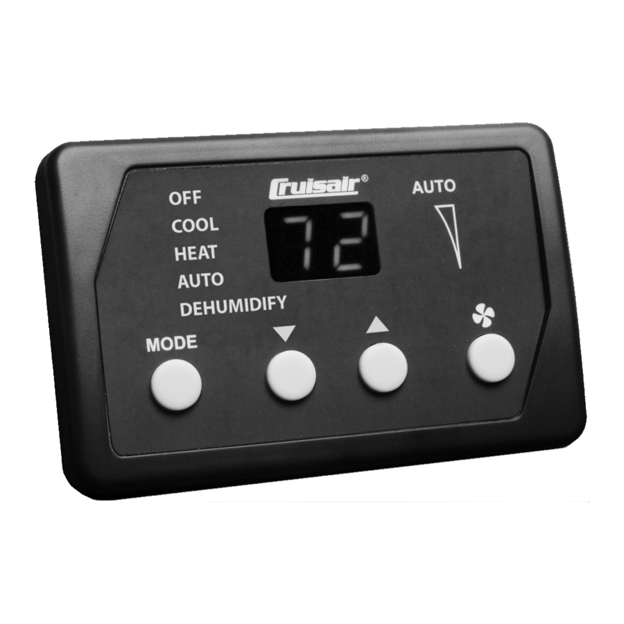
Q3 Control
Dometic Marine
Rev. 20170710
Part Number 332456
L-2962 English
COPYRIGHT © 2007-2017 Dometic Corporation. All Rights Reserved.
No part of this publication may be reproduced, translated, stored in a retrieval system, or transmitted in any form or by any means
electronic, mechanical, photocopying, recording or otherwise without prior written consent by Dometic Corporation. Every precaution
has been taken in the preparation of this manual to ensure its accuracy. However, Dometic Corporation assumes no responsibility for
errors and omission. Neither is any liability assumed for damages resulting from the use of this product and information contained
herein.
Qht Control (with bezel)
Advertisement
Table of Contents
Troubleshooting

Related Manuals for Dometic Q3


Summary of Contents for Dometic Q3
- Page 1 Dometic Corporation. Every precaution has been taken in the preparation of this manual to ensure its accuracy. However, Dometic Corporation assumes no responsibility for errors and omission. Neither is any liability assumed for damages resulting from the use of this product and information contained...
-
Page 2: Table Of Contents
Table of Contents INTRODUCTION ....... 1 FAULT AND ERROR MESSAGES ....12 . -
Page 3: Introduction
Q-Logic Only" label displayed on the Qht mounting flange. While the programming procedure of the Q3 and Qht controls is the same, there are differences in the look of the buttons and and the way the information is presented in the displays. Differences are noted in this manual where applicable. Familiarize yourself with the operation and programming sections of this manual. -
Page 4: Description Of The Controls
ONTROLS Figure 1: Q3 Diagram - Control Display Panel and Indicators 13,14 15,16 Table 1: Q3 Diagram Description of Control Display Panel and Indicators Data Display AUTO Mode Indicator - Large LED readout displays current Lights when Auto Mode is selected. - Page 5 Q3 & Qht Controls for Chilled Water Systems Description of the Controls Figure 2: Qht Diagram - Control Display Panel and Indicators Table 2: Qht Diagram Description of Control Display Panel and Indicators Data Display - Large LCD readout displays current temperature,...
-
Page 6: Important Programming Notes To Installer And End User
For the Qht display, make a rectangular cut-out in the panel where it will be mounted. The Qht cut-out size is 3-7/16” (88mm) wide by 2-1/8” (54mm) high. For the Q3 display, only a 1” (26mm) round hole is required in the panel for mounting. -
Page 7: Loop Outlet Temperature Sensor Optional
PERATOR ONTROLS AND ISPLAY ANEL For the button locations and display functions, refer to Figure 1, Table 1 on page 2 for the Q3 control and to Figure , Table 2 on page 3 for the Qht control. UTTON UNCTIONS •... -
Page 8: Modes Of Operation
ODES Press the MODE (Q3) or POWER (Qht) button to turn the system on. In three seconds, the system will start operating in whichever mode it was running prior to the last shut down. For the initial startup, the control will be in Run Mode.To change mode before the system starts, press the MODE button before the three-second startup completes (while the display is flashing). -
Page 9: Display Inside Cabin Temperature
Press the MODE and UP buttons simultaneously and repeatedly to select the brightness setting for the display. LEEP Sleep Mode dims all LEDs (Q3) or turns off the backlight (Qht). When in Sleep Mode, press any button to brighten the display, and then operate as usual. See Programmable Function “11: Sleep Mode” on page 9. -
Page 10: Restoring Factory Default Settings
Q3 and Qht Controls for Chilled Water Systems Programmable Functions ESTORING ACTORY EFAULT ETTINGS You can restore the original factory default settings and overwrite all the customized changes you made. To restore the factory default settings, switch to Off Mode and then press and hold the UP and DOWN buttons simultaneously. Hold the buttons for three seconds while “00”... - Page 11 (Factory Default: On) You can set the Q3’s LED brightness level to dim or you can set the Qht’s backlight to be on or off. Select “SL” for Sleep Mode and the LEDs will remain dim or the backlight will remain off until a key is pressed, which will temporarily brighten the display.
- Page 12 8). The default is set at 5 fan-speed divisions. • Q3 - Displays either the individual High, Medium and Low fan-speed LEDs if 3 speeds are selected, or a combination of the High, Medium and Low fan-speed LEDs if 5 speeds are selected, for example: •...
- Page 13 Q3 & Qht Controls for Chilled Water Systems Programmable Functions 22: Dehumidification Overall Time Period (Factory Default: 12 hours) This setting determines how often the system performs the dehumidification process. The display shows the overall time period in hours. You can select intervals of 2, 4, 6, 8, 10, 12, 14 or 16 hours. Choose a shorter overall time period in climates with high humidity and a longer overall time period in climates with low humidity.
-
Page 14: Summary Table Of Programmable Functions
To protect the equipment, certain fault conditions trigger a shutdown, and the system will not restart until the fault is repaired. If an operational failure occurs, the display will flash one of the following fault or error code messages. Fault code displays are canceled by pressing the MODE button (Q3) or POWER button (Qht). L-2962 ENGLISH... -
Page 15: Summary Of Fault Codes And Indicator Codes
Outside / - - page 5 for instructions. IL or Water Displays supply (input) loop water temperature at air handler as IL (Q3) or Water (Qht) Continue Operation / 1st digit / 2nd then the first digit followed by second two digits. See “Button Functions” on page 5 for 2 digits instructions. -
Page 16: Troubleshooting
Before you call for service, review this list. It may save you time and expense. This list contains common occurrences that are not a result of defective workmanship or materials. If you need service after trying these procedures, call your nearest Dometic dealer. -
Page 17: Digital-Controls Troubleshooting
Digital-Controls Troubleshooting IGITAL ONTROLS ROUBLESHOOTING See also “General System Troubleshooting” on page 14. Contact an authorized Dometic servicing dealer if the problem continues or for replacement parts. Table 7: Digital-Controls Troubleshooting PROBLEM POSSIBLE REASON/SOLUTION Digital display panel is not 1. No power. Turn circuit breaker on. -
Page 18: Maintenance Of System Components
IMENSIONS Q3 Display Panel ..... . .3.50” (89mm) W x 2.53" (65mm) H x 0.75” (19mm) D Qht Display Panel ........4.84” (123mm) W x 3.27" (83mm) H Qht Panel Cut Out . -
Page 19: Sample Wiring Diagrams
Q3 & Qht Controls for Chilled Water Systems System Inputs SAMPLE WIRING DIAGRAMS IMPORTANT These are sample diagrams. Wire colors may vary. See unit’s specific diagram located in electrical box. Turn power off before opening electrical box. Figure 3: Sample Digital Control Wiring Diagram (U-Board) - Page 20 Q3 and Qht Controls for Chilled Water Systems System Inputs Figure 4: Sample Digital Control Wiring Diagram (obsolete board) L-2962 ENGLISH...
- Page 21 NOTES...
- Page 22 NOTES...
- Page 23 NOTES...
- Page 24 DOMETIC MARINE DIVISION 2000 N. Andrews Ave. Pompano Beach, FL 33069 USA +1 954-973-2477 +1 954-979-4414 Email MarineSales@dometic.com 24/7 TECH SUPPORT FOR UNITED STATES AND CANADA 8:00 AM to 5:00 PM Eastern Time: +1 800-542-2477 After hours and weekends: +1 888-440-4494...
Need help?
Do you have a question about the Q3 and is the answer not in the manual?
Questions and answers