Table of Contents
Advertisement
Quick Links
MITSUBISHI MOTION CONTROLLER
Safety signal module Q173DSXY
Thank you for purchasing the Mitsubishi Motion controller.
The Motion controller is suitable for establishing safety functions for
general industrial machinery.
Prior to use, please read both this manual and detailed manual
thoroughly and familiarize yourself with the product.
All rights reserved • Specified product properties and technical data do not represent
a guarantee declaration.
© 2012 MITSUBISHI ELECTRIC CORPORATION
Safety Information
Advertisement
Table of Contents

Related Manuals for Mitsubishi Q173DSXY


Summary of Contents for Mitsubishi Q173DSXY
- Page 1 MITSUBISHI MOTION CONTROLLER Safety signal module Q173DSXY Safety Information Thank you for purchasing the Mitsubishi Motion controller. The Motion controller is suitable for establishing safety functions for general industrial machinery. Prior to use, please read both this manual and detailed manual thoroughly and familiarize yourself with the product.
- Page 2 Chapter 8 This manual confers no industrial property rights or any rights of any other kind, nor does it confer any patent licenses. Mitsubishi Electric Corporation cannot be held responsible for any problems involving industrial property rights which may occur as a result of using the contents noted in this manual.
-
Page 3: About This Manual
1 About this manual 1.1 Related Manuals This manual describes the mounting of the safety signal module (Q173DSXY) of a Motion controller. For detailed information of the products, refer to each user's manual or programming manual. Can obtain the PDF data of latest manual from our website. -
Page 4: Qualified Safety Personnel
2 On safety This chapter deals with your own safety and the safety of the equipment operators. • Please read this chapter carefully before beginning with the installation. 2.1 Qualified safety personnel The Motion controller may only be installed by qualified safety personnel. Qualified safety personnel are defined as persons who …... - Page 5 Mitsubishi Electric Corporation accepts no claims for liability if the equipment is used in any other way or if modifications are made to the device, even in the context of mounting and installation. UL/CSA applications: • Use 60°C/75°C conductors. • The terminal tightening torque must be 5-7 lbs in.
-
Page 6: General Protective Notes And Protective Measures
• Manufacturers and owners of the machine on which a Motion controller is used are responsible for obtaining and observing all applicable safety regulations and rules. For Declaration of Conformity (DoC), MITSUBISHI ELECTRIC EUROPE B.V., declares that the Motion controllers are in compliance with the necessary requirements and standards (2006/42/EC, 2004/108/EC and 2006/95/EC). - Page 7 • At the shipment to end-users, confirm the safety related setting by monitoring status and displayed details of the programming tools and displays. Also, record and save the setting data of safety-related information and programming tools by using check sheet, etc. •...
- Page 8 (2) Speed monitoring function (SLS) • Under the condition that the failure rate of the additional pulse encoder components does not exceed 195FIT/395FIT the resulting PFD/PFH will be less than 195FIT/395FIT. (See below diagram.) Q17 DSCPU Q173DSXY Motion Encoder MR-J4- B Motion ch A Common Comp.
- Page 9 (4) Shut-off function (STO, SS1) • STO function disables energy supply to the servo motor by electrical shut-off. The function does not mechanically disconnect electricity from the motor. Therefore, it cannot prevent exposure to electric shock, install a magnetic contactor or a molded case circuit breaker to the main circuit power supply (L1, L2, and L3) of the servo amplifier.
- Page 10 MEMO...
-
Page 11: Conditions Of Use For The Product
• Passing on the output information to the Motion CPU and PLC CPU module. Q173DSXY is not available separately from Motion controller and PLC. Please use with Motion controller and PLC. Up to three Q173DSXY are used on one base unit. It can not be used on the extension base unit. -
Page 12: Name Of Parts
4.2 Name of parts (1) PLC CPU module QnUDE(H)CPU Q03UDECPU EJECT Q03UDECPU MODE MODE ERR. ERR. USER USER BAT. BAT. BOOT BOOT RESET RUN PULL STOP 10BASE-T/100BASE-TX 10BASE-T/100BASE-TX Name Application MODE LED Indicates the mode of the CPU module. Indicates the operating status of the CPU module. RUN LED : RUN OFF : STOP... - Page 13 For the connection with Safety signal module RIO connector (Q173DSXY) connector. (Note-1): In the case of monitoring or writing the safety sequence program of the Motion CPU, communicate from the peripheral devices (GX Works2/GX Developer) by setting the rotary switch to "1".
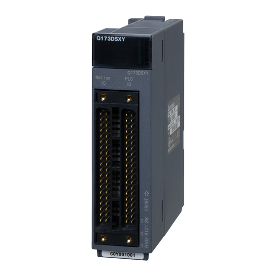
- Page 14 (3) Safety signal module Q173DSXY Front Face Bottom Q173DSXY Q173DSXY Motion Name Application I/O indicator Used to indicate the I/O status (on/off). (Only the PLC) Motion IO The safety signal connector Motion CPU connector PLC IO The safety signal connector PLC CPU...
- Page 15 4.3 Pin layout of safety signal module connector Signal Signal Signal name Signal name Type Type 1B20 MC-X00 2B20 PLC-X00 1B19 MC-X01 2B19 PLC-X01 1B18 MC-X02 2B18 PLC-X02 MC-X03 2B17 PLC-X03 1B17 MC-X04 2B16 PLC-X04 1B16 MC-X05 2B15 PLC-X05 1B15 MC-X06 2B14 PLC-X06...
-
Page 16: External Wiring Diagram
4.4 External wiring diagram 1B20 1A11 (Only PLC) Internal circuit 1B10 1A05 DC24V 1B02 1B01 1A02 1A01... -
Page 17: Mounting The Modules
5 Mounting/Dismantling 5.1 Mounting the modules Base unit Base unit Module connector Module fixing projection Module mounting lever Module Module fixing hole Module Module fixing fixing projection projection Module mounting Module fixing hole lever Module fixing hole Base unit Base unit Module fixing hook Module fixing projection... - Page 18 5.2 Removal Push Module fixing hook Base unit Module Module connector Module fixing hole Liftting Pul l • When the module fixing screw is used, always remove the module by removing the module fixing screw and then taking the module fixing projection off the module fixing hole of the base unit.
- Page 19 6 Wiring De-energize the entire system The system could start up unexpectedly while you are connecting the devices. CAUTION • Select the wire and DC power supply to keep input voltage in the range of 21.6 to 26.4VDC including the ripple voltage and voltage spike to the safety signal module which is measured at the input connector.
-
Page 20: General Specifications
7 Technical data 7.1 Safety specification Item Specification Category Category3 (EN ISO13849-1) Safety Integrity Level SIL CL2 (EN62061) Performance Level PL d (EN ISO13849-1) MTTFd 169 years or longer 2.17×10 Safety signal comparison, Safety functions STO, SS1, SS2, SOS, SLS, SBC, SSM (IEC61800-5-2:2007) (Note): Scope of the safety specifications is only processing block. - Page 21 Included items (Note-1) Battery cable (Q170DBATCBL05M)×1 Safety Guidelines (IB-67423)×1 (Note-1): Q17 DCPU-S1 Only 7.5 Safety signal module Q173DSXY Specifications Item Specification 32 inputs × 2 paths (32 for PLC CPU control + 32 for Motion CPU Number of inputs control, 20 safety inputs × 2 paths and 12 feedback inputs × 2 paths)
- Page 22 8 Check list for user documentation MITSUBISHI ELECTRIC Motion controller installation checklist for manufacturer/installer The following items must be satisfied by the initial test operation at least. The manufacturer/installer must be responsible for checking the standards in the items. Maintain and keep this checklist with related documents of machines to use this for periodic inspection.
- Page 23 MEMO...
- Page 24 WARRANTY Please confirm the following product warranty details before using this product. 1. Gratis Warranty Term and Gratis Warranty Range We will repair any failure or defect hereinafter referred to as "failure" in our FA equipment hereinafter referred to as the "Product" arisen during warranty period at no charge due to causes for which we are responsible through the distributor from which you purchased the Product or our service provider.
- Page 25 2. Onerous Repair Term after Discontinuation of Production (1) We may accept the repair at charge for another seven (7) years after the production of the product is discontinued. The announcement of the stop of production for each model can be seen in our Sales and Service, etc.
- Page 26 Tel: 48-12-630-4700 Fax: 48-12-630-4701 Setsuyo Enterprise Co., Ltd. German FA Center 3F., No.105, Wugong 3rd, Wugu Dist, Mitsubishi Electric Europe B.V. - German Branch New Taipei City 24889, Taiwan, R.O.C Gothaer Strasse 8, D-40880 Ratingen, Germany Tel: 886-2-2299-9917 Fax: 886-2-2299-9963...