Sign In
Upload
Manuals
Brands
Eaton Manuals
Control Unit
Digitrip RMS 910
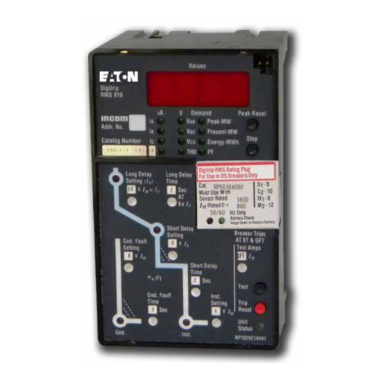
Eaton Digitrip RMS 910 Manuals
Manuals and User Guides for Eaton Digitrip RMS 910. We have
4
Eaton Digitrip RMS 910 manuals available for free PDF download: Instructions Manual, Instruction Leaflet, Instructional Leaflet
Eaton Digitrip RMS 910 Instructions Manual (79 pages)
Application ol Retrolit Kits on Power Circuit Breakers
Brand:
Eaton
| Category:
Industrial Electrical
| Size: 10 MB
Table of Contents
Table of Contents
2
Safety Precautions
6
Warranty Disclaimer and Liability
7
Section 2 Digitrip
8
Digitrip RMS Retrofit Kits
8
Retrofit Kit Lnstallation Requirements
8
The Retrofit Process
9
Digitrip RMS Retrofit Kit
9
Section 3 the Digitrip RMS Trip
12
Current Sensors and Sensor Wiring
12
Auxiliary CT Module and Auxiliary CT
12
Harness
12
Digitrip RMS Trip Unit and Power Relay Module (ATR)
12
System
12
And 60 Hz)
16
Digitrip RMS
20
Cell Harness Assembly
21
Breaker Mounted Control Power Transformer
21
Digitrip RMS 510 Basic
22
Digitrip RMS 510 Basic Retrofit Kit Features
22
Selection and Content
22
Rms 510
23
Retrofit Kits
24
Digitrip RMS 510 Retrofit Kit
24
Zone Lnterlocks) Selection and Content
24
Digitrip RMS 61O
26
Digitrip RMS 610 Retrofit Kit
26
Kits
26
Rms 810 & 910
28
Selection and Content
28
Power Flow Convention
30
Power Flow Conventions
30
Powernetcommunicationswiring Checkout
31
Retrofit Kits
33
Recommended Testaccessories
33
Explanation of Test Procedures
34
Primary Lnjection Testing
37
Digitrip RMS Self-Testing System
40
Self-Testing
40
Digitrip RMS 810 & 910 PT Module
40
Self-Testing of the Digitrip Trip
41
Testing Digitrip with the
43
Secondary Lnjection
43
DS Breaker Secondary Lnjection
45
Circuit Breaker Checkout and Bench Test
47
Section 9 Operation
48
And Power up
48
Lnformation Available
50
Trip
50
Resetting the Trip Unit after a
51
Removing the Breaker from the CONNECT Position
51
Section 10 Digitrip RMS Retrofit
52
Zone .10.1.1
53
10.4 the Power Relay Module
58
10.5 Communications and Powernet
58
Of Trip
58
Typical ATR 120 VAC Source Lnput
59
Alarm Lndication
59
Typical Control Schematic Without CC1 CC2 Modification
60
CC1 CC2 Modification
60
CC1 CC2 Modification to Typical Control Schematic (Stored Energy)
60
CC1 / CC2 Modification to a Typical Control Schematic (Solenoid)
60
2-5 Auxiliary CT Harness
64
12.3 Auxiliary CT Module Wiring
64
Without Ground
65
Digitrip RMS 510 External Harness
68
Digitrip RMS
68
Digitrip RMS 510 Cell Harness
70
Cell Harness
70
Simplified Cell Harness
72
Digitrip RMS
72
Advertisement
Eaton Digitrip RMS 910 Instruction Leaflet (32 pages)
Trip Unit
Brand:
Eaton
| Category:
Control Unit
| Size: 1 MB
Table of Contents
Table of Contents
2
Important Safety Instructions
4
General Description - Digitrip RMS 910
4
Trip Unit
4
Basic Digitrip RMS 910 Trip Unit
4
Operational Status and Protection TRIP Indicators
5
Figure 1. Digitrip RMS 910 Trip Unit Type LSIG with Rating Plug
5
General Over-Current Protection
6
Figure 2. RMS Digitrip 910 Trip Unit - Block Diagram
6
Figure 3. Digitrip RMS 910 Type Ll
8
Figure 4. Digitrip RMS 910 Type LS
8
Figure 5. Digitrip RMS 910 Type LSI
8
Figure 6. Digitrip RMS 910 Type LIG
8
Discriminator (High Initial Current Release)
9
(For Types LS and LSG Trip Units Only)
9
Figure 7. Digitrip RMS 910 Type LSG
9
Figure 8. Digitrip RMS 910 Type LSIG
9
OVERRIDE (Fixed Instantaneous)
10
Zone Interlocking
10
Four Character Information Display Window
10
Values Displayed During Normal Service
10
Instrumentation - Current Values
10
Instrumentation - Voltage Values
12
Instrumentation - Power, Power Factor and Energy
13
Values
13
Figure 9. Rating Plug
13
Harmonics [THD]
14
Messages Displayed after ALARM or TRIP
14
Figure 10 . Power/Relay Module
14
Figure 11. Potential Transfer Module
14
ROM Error
15
Plugs
15
Power / Relay Module
15
Figure 12. Auxiliary Power Module
15
Potential Transformer Module
16
Figure 13. Long Delay Current Settings
16
Figure 14. Long Delay Time Settings
16
Figure 15. Short Delay Current Settings
16
Auxiliary Power Module
17
Figure 16. Short Delay Time Settings
17
Figure 17. Instantaneous Current Settings
17
Figure 18. Ground Fault Current Settings
17
UL Listed Devices
17
Protection Settings
18
General
18
Long Delay Current Setting
18
Long Delay Time Setting
18
Short Delay Current Setting
18
Short Delay Time Setting
18
Instantaneous Current Setting
18
Figure 19. Ground Fault Time Delay Settings
18
Figure 20. Integral Test Panel (Lower Right Corner of Trip Unit)
18
No Instantaneous Current Setting
19
Ground Fault Current Setting
19
Ground Fault Time Delay Setting
19
Test Procedures
19
General
19
When to Test
19
Testing Provisions
20
Conducting Tests
20
Not Tripping the Breaker
21
Tripping the Breaker
21
Testing the Back-Up Battery (Inside the Rating Plug)
21
Back-Up Battery Check
21
Replacing the Back-Up Battery
21
Figure 21. INCOM with Remote Master Computer
22
Communications
22
Figure 22. INCOM Network with AEM / BIM
23
Figure 23 . INCOM Network with Remote Master Computer and
23
Trip Unit Address and Baud Rate
24
Assemblies Electronic Monitor (AEM-II) and Breaker
26
Interface Monitor (BIM)
26
Both Remote Master Computer and AEM / BIM
26
INCOM ® Network Interconnections
26
Information Communicated by Digitrip RMS 910
26
Remote Closing and Tripping of Circuit Breakers
26
Remote Master Computer
26
Waveform Capture
26
Remote Resetting of the Trip Unit
27
References
27
Digitrip RMS Trip Assemblies
27
Type DS Low-Voltage AC Power Circuit Breakers
27
Type DS II Low-Voltage AC Power Circuit Breakers
27
Type SPB Systems Pow-R
27
Series C ® R-Frame Molded Case Circuit Breakers
28
Assemblies Electronic Monitors
28
Incom ® and Impacc ® Communications
28
APPENDIX A: Zone Lnterlocking
28
Figure A.1 Typical Zone Interlocking (Ground Fault Protection)
29
Figure a .2 Typical Zone Interlocking Connections with Two Main
29
Breakers (M1, M2) and a Tie Breaker (T)
29
Trips
29
APPENDIX B: Interpreting Display Codes after Circuit Breaker
29
Eaton Digitrip RMS 910 Instructional Leaflet (24 pages)
Trip Units with Types DSII and DSLII Low Voltage Power Circuit Breakers
Brand:
Eaton
| Category:
Circuit breakers
| Size: 1 MB
Table of Contents
Table of Contents
1
1 Supplementary Information
2
2 Digitrip RMS and Digitrip OPTIM Trip Units
2
3 Rating Plugs
3
4 Digitrip RMS Model Considerations
5
Digitrip RMS 510
6
Digitrip RMS 610
6
Digitrip RMS 810
9
Digitrip RMS 910
10
Digitrip OPTIM Model Considerations
10
Digitrip OPTIM 750
10
Digitrip OPTIM 1050
11
5 Principle of Operation
12
General
12
Digitrip RMS Trip Assembly
12
Trip Actuator
12
Ground Fault Protection
13
Current Sensors
14
Potential Transformer Module
15
6 Testing
15
Functional Field Testing
15
Secondary Injection Testing
15
Performance Testing for Ground Fault Trip Units
18
Code Requirements
18
Standards Requirements
18
General Test Instructions
18
7 Record Keeping
18
8 Low Voltage Power Circuit Breaker References
19
Digitrip RMS and Digitrip OPTIM Trip Assembly References
19
Time-Current Curves
19
Miscellaneous References
19
Advertisement
Eaton Digitrip RMS 910 Instructions Manual (36 pages)
Brand:
Eaton
| Category:
Industrial Equipment
| Size: 4 MB
Advertisement
Related Products
Eaton RPM-3Ui
Eaton OPTCB RS-485
Eaton Vickers RG-03 1 Series
Eaton Vickers RG-06 1 Series
Eaton Vickers RCT-06 1 Series
Eaton Vickers RCT-10 1 Series
Eaton Vickers RCG-10 1 Series
Eaton Digitrip RMS 510 LI
Eaton Digitrip RMS 510 LIG
Eaton Digitrip RMS 310
Eaton Categories
UPS
Circuit breakers
Switch
Industrial Equipment
Industrial Electrical
More Eaton Manuals
Login
Sign In
OR
Sign in with Facebook
Sign in with Google
Upload manual
Upload from disk
Upload from URL