
Related Manuals for Apera Instruments 9500 Premium Series


Summary of Contents for Apera Instruments 9500 Premium Series
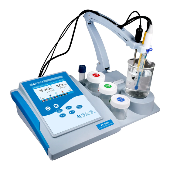
- Page 1 9500 Premium Series Benchtop pH/Conductivity Meter User Manual PH9500 Benchtop pH Meter EC9500 Benchtop Conduct ivity Meter PC9500 Benchtop pH/ Conductivity Meter APERA INSTRUMENTS, LLC aperainst.com...
-
Page 2: Table Of Contents
Introduction ................................- 1 - Parameters ............................. - 1 - Basic Features and Functions ......................- 1 - Features of pH Measurement ......................- 1 - Features of Conductivity Measurement ..................- 2 - Technical Specifications ............................- 2 - Technical Parameters ........................ - Page 3 5.1.2 5-point Calibration ..............................- 15 - 5.1.3 Calibration Frequency ............................... - 16 - 5.1.4 Check calibration record ............................- 16 - 5.1.5 pH Calibration Reminder ............................- 16 - pH Meter Calibration ........................- 16 - User-Define Calibration (take 2.00 pH and 7.30 pH as an example) ........... - 19 - Self-Diagnosis ..........................
- Page 4 Salinity Types ..........................- 32 - Back to Factory Default Settings ....................- 32 - 7.10 Conductivity Electrode Maintenance .................... - 32 - Data Processing Modes (Save, Recall, Print, Delete) ..................- 33 - Data Processing Flowchart ......................- 33 - Log Data in Meter .........................
-
Page 5: Introduction
Introduction Thank you for choosing Apera 9500 Premium Series Benchtop pH/Conductivity Meter. Before using this product, please read this manual carefully. 9500 Series Benchtop Meter is an outstanding combination of advanced electronic technology, sensor technology and intuitive software design, made for laboratory pH and conductivity measurement in scientific research and quality control, fully meeting GLP (Good Laboratory Practice) standards. -
Page 6: Features Of Conductivity Measurement
Features of Conductivity Measurement • 1 to 4 points of automatic calibration with calibration instruction and automatic checking functions. • Automatically recognize conductivity standard solutions. 2 series standard solution available: Standard Series and CH Series, as well as User-Define solution (any conductivity standard solutions). •... -
Page 7: Others
Range 0.00 to 100 ppt Resolution 0.01/0.1 ppt EC9500 Salinity Accuracy ±1.0% F.S ±1 digit PC9500 Temp. Compensation Range 0 to 50°C (auto. or manual) Salinity Type Linear / NaCl / Saltwater 0.00 Ω·cm to 100MΩ·cm Range 0.1/1 Ω·cm; 0.01/0.1/1KΩ·cm; 0.1 Resolution EC9500 MΩ·cm... -
Page 8: Measurement Interfaces
Measurement Mode Measurement Unit ① ⑪ pH Measurement Auto. Hold ② ⑫ mV value of pH electrode Stable reading ③ ⑬ Electrode ID Date and time ④ ⑭ Current stirring Saved stirring Completed calibration(s) ⑤ ⑮ speed speed Sample ID Auto. - Page 9 Conductivity Measurement Interface applicable models: EC9500/PC9500 ①-- Conductivity measurement mode ②-- Conductivity measurement ③-- Conductivity parameters (see section 7.1.2, 7.2.5, 7.2.6) ④-- Completed conductivity calibration(s) ⑤-- Temperature measurement ⑥-- Stable reading ⑦-- Date and time TDS Measurement Interface applicable models: EC9500/PC9500 ①-- TDS measurement mode ②-- TDS measurement ③-- TDS conversion factor (see section 7.7)...
-
Page 10: Keypad
Keypad Diagram-2 3.3.1 Keypad Operation Short press – Press key and hold for less than 2 seconds, buzzer makes a beep; Long press – Press key and hold for more than 2 seconds, buzzer makes a beep when short pressing the button, another beep will ring after holding the key for 2 seconds. -
Page 11: Function
• In measurement mode: press to enter parameter set-up main menu; • In calibration mode: press to perform calibration; • In main menu: press to enter submenu; Short • In submenu: press to enter parameter set-up; press • In parameter set-up mode: press to confirm parameter; •... -
Page 12: Meter Sockets
Meter Sockets Diagram-4 Table - 2 Meter Sockets Information Socket Type Information Connect pH or ORP combination electrode ① Ф2 power supply Connect magnetic stirrer ② Connect temperature sensor (for pH) ③ Connect printer ④ Connect PC ⑤ Ф4 banana Connect reference electrode ⑥... -
Page 13: Reading Mode
Reading Mode 3.5.1 Stable Reading Mode When reading is stable, shows up. If you don’t see the smiley face or it’s flashing, it means the reading is not fully stabilized and it’s not the right timing to record or calibrate. 3.5.2 Auto. -
Page 14: Meter Installment
Meter Installment 3.6.1 Connect Test-Bench Before installment After installment Test-Bench Meter Stirrer cable Connecting board Diagram-5 3.6.2 Install flexible electrode holder Align the hole and bar, then press down with force. Diagram-6 3.6.3 How to use Test-Bench (a) Use in a connected manner (b) Use in a separated manner Diagram-7 - 10 -... -
Page 15: Magnetic Stirrer Operation
Magnetic Stirrer Operation 3.7.1 Technical Specifications Speed Range 0 to 2300 RPM (no load) Working area diameter Ф100mm Max. stirring volume 1000mL 3.7.2 Operation (a) Insert the stirrer cable to the corresponding sockets in meter and stirrer. (b) Short press to power on stirrer, will show up on the top of the display. -
Page 16: Parameter Settings
Parameter Settings 4.3.1 Main Menu and Sub-menu Main Menu pH sub-menu Conductivity/TDS sub-menu Data management Sub-menu Settings Sub-menu Diagram-9 - 12 -... -
Page 17: Operation
4.3.2 Operation For detailed operation, please follow the instruction at the bottom of screen. 4.3.3 Parameter Settings Content Main Parameter Settings Content Default Info Menu Refer to pH buffer standard USA/NIST/CH/User-Define section 5.1.1 Resolution 0.001/0.01/0.1 0.01 Refer to Calibration info View/Print Check section 5.1.4... -
Page 18: Calibration Password
Refer to User ID --------- section 3.3.3- Refer to Company name --------- section 8.3.3- Refer to Calibration password --------- section 4.4 Refer to Display info Simple/Complete section 4.2 Refer to Auto. Hold On-Off section 3.5.2 Temperature unit °C - °F YYYY-MM-DD/MM-DD- Date format YYYY/DD-MM-YYYY... -
Page 19: 5-Point Calibration
Table-3 pH Standard Buffer Series pH Standard Buffer Series Calibration Icon NIST 1.679 pH 1.680 pH 1.680 pH 4.005 pH 4.003 pH 4.003 pH 5-point 7.000 pH 6.864 pH 6.864 pH Calibration 10.012 pH 9.182 pH 9.182 pH 12.454 pH 12.454 pH 12.460 pH Note: the calibration icons are examples of USA standard series. -
Page 20: Calibration Frequency
5.1.3 Calibration Frequency The frequency that you need to calibrate your meter depends on the tested samples, condition of electrodes, and the requirement of the accuracy. For High-Accuracy measurement (≤ ±0.02pH), the meter should be calibrated before test every time; For general-accuracy measurements (≥±0.1pH), once calibrated, the meter can be used for about a week or longer. - Page 21 Table-5 pH Meter 3-point Calibration 1. Long press to enter calibration mode. Rinse off the electrode with distilled or deionized water. Shake-dry or dry with filter paper. Then insert the electrode into 7.00 pH buffer. Press to continue. 2. Stir the electrode gently, let it stand in 7.00 pH buffer, and wait for to show up and stay on screen (the buzzer will make a beep).
- Page 22 5. When pH 4.00 is calibrated, the 4.00 icon will show up at the bottom left corner. The meter will automatically enter the next point of calibration. Rinse off the electrode with distilled or deionized water. Shake-dry or dry with filter paper.
-
Page 23: User-Define Calibration (Take 2.00 Ph And 7.30 Ph As An Example)
User-Define Calibration (take 2.00 pH and 7.30 pH as an example) Table-6 pH Meter User-Define Calibration 1. In parameter setting 1.1, select User, press confirm. Then press to go back to measurement mode. 2. Long press to enter calibration mode. Rinse off the electrode with distilled or deionized water. -
Page 24: Self-Diagnosis
6. After 7.30 pH is calibrated, the meter will display calibration record for a few seconds and go back to measurement mode. The calibration icons of 2.00 and 7.30 will show up at the bottom left. Note that in user- define calibration, the icons are in black. -
Page 25: Sample Measurement
Table-7 pH Self-Diagnosis Information Message Detailed information How to fix 1. Check if pH buffer is correct (1st point must be 7.00 or 6.86). 2. Check if pH buffer is in good Incorrect pH buffer, exceeding the Buffer error quality (fresh and clean). meter’s recognizable range 3. -
Page 26: About Ph Measurement
About pH Measurement 5.6.1 pH Stability Criterion pH stability criterion refers to the time it takes for pH readings to stabilize, which is related to the ion concentration (iconic strength) of test samples. Generally, the higher the ion concentration, the faster the readings get stabilized. -
Page 27: Ph Isothermal Measurement Principal
◆ Min-Max alarm If the reading is lower than the minimum value or higher than the maximum value, reading alarm goes off. For example, if minimum value is set to 6.50 pH, and maximum value is set to 7.60 pH, when measurement is lower than 6.50 pH or higher than 7.60 pH, shows up, and the buzzer makes a beep. -
Page 28: Calibration Solutions
5.7.2 Calibration Solutions To maximize the meter’s measurement accuracy, pH buffers should be fresh and clean. After multiple uses, replace pH buffers in time. 5.7.3 Cleaning pH electrodes must be thoroughly rinsed with pure water before and after each test. For tough contaminants, users can use a soft brush and warm soap water to clean off. -
Page 29: Ise Measurement
ISE Measurement Connect the ion electrode, insert it in the test sample, stir gently and let it stand. Get the reading when shows up and stays on screen, which is the potential value of the ion electrode. If the ion electrode is a combination type, simply insert it to the pH/mV socket. -
Page 30: Calibration Frequency
7.2.2 Calibration Frequency a) The meter has been calibrated before leaving factory and can be used directly by the user. b) It is recommended to calibrate once a month under normal circumstances. c) If the accuracy requirement is high or the measured temperature is significantly different to the reference temperature (25 °C), it is recommended to calibrate once a week;... -
Page 31: Temperature Compensation Coefficient
7.2.6 Temperature Compensation Coefficient The temperature compensation coefficient of the factory setting is 2.00%/°C, but the conductivity temperature compensation coefficients of different kinds and different concentration solutions are different. Users can refer to Table-11 and the data obtained from experiments. Set the setting in 2.6 (temperature compensation coefficient). -
Page 32: Conductivity Meter Calibration (Take 1413Μs/Cm As An Example)
Conductivity Meter Calibration (Take 1413μS/cm as an example) 1. Long press to enter calibration mode. Rinse off the electrode with distilled or deionized water. Shake-dry or dry with filter paper. Press to continue. 2. Insert the electrode to 1413μS/cm solution. Stir gently and let it stand still. -
Page 33: User-Define Calibration (Take 10Μs/Cm As An Example)
User-Define Calibration (Take 10μS/cm as an example) 1. In parameter 2.2, select “user”, press to confirm. Then press to return to measurement mode. 2. Long press to enter calibration mode. Rinse off the electrode with distilled or deionized water. Shake-dry or dry with filter paper. -
Page 34: Self-Diagnosis
Self-Diagnosis The meter has a self-diagnosis function for conductivity. When the electrode is not working properly, calibration solutions are incorrect, or operation is incorrect, relevant information will pop up at the bottom of the display as shown in Diagram-19. At the same time, the buzzer will make two beeps. For detailed information of self- diagnosis, refer to Table-12. -
Page 35: Sample Measurement
Sample Measurement Rinse the conductivity electrode with distilled or deionized water. Shake-dry or dry with filter paper. Insert it to sample solution, stir a few seconds and let it stand. Record the reading when shows up and stays on screen. Diagram-20 is the flowchart for conductivity calibration and measurement. Measure Insert the electrode to 84 μS solution, Long press... -
Page 36: Salinity Types
Salinity Types The salinity types are linear salinity, NaCl salinity and saltwater salinity. The linear salinity is calculated according to the measured conductivity value (0.5 conversion factor). The NaCl salinity and saltwater salinity are programmed based on 2 predetermined salt curves. The salinity type can be set in parameter setting 2.8 and the meter is factory set to “linear”... -
Page 37: Data Processing Modes (Save, Recall, Print, Delete)
Data Processing M odes (Save, Recall, P rint, Delete) Data Processing Flowchart The data storage has three modes: “memory”, “printer” and “computer”, as well as “manual” and “auto. timing” data logging modes. Diagram-22 is a flowchart explaining various storage and data logging modes. In parameter setting ●... -
Page 38: Log Data In Meter
Log Data in Meter 8.2.1 Setup Select Memory in parameter setting 3.1. displays on top of the screen. All data will be stored in the meter. 8.2.2 Data Storage The PH9500 and EC9500 models has a storage capacity of 1000 sets, and the PC9500 can store 2000 sets. -
Page 39: Print Data
(b) Auto. timing data log Select “Timer” in parameter setting 3.2 and set the data logging interval time (by every X seconds or minutes), for example, 10 seconds, press to start auto. data logger, flashes, the first set of measurement data is stored and shows up, then every 10 seconds one set of data will be stored and the storage number will be automatically increased. -
Page 40: Printer Information
8.3.3 Printer Information (a) Complete format Selecting “Complete” in parameter setting 3.3 to use the complete printing format. The printing information includes device information, calibration information, and measurement data. The device information refers to the instrument model number, serial number, electrode ID, company name, and operator ID; the calibration information refers to the last calibration record;... -
Page 41: Data Logging Via Pc
Data logging via PC 8.4.1 Install Software a) This instrument uses the PC-Link 9500 communication software, and the communication port is USB. Copy the PC-Link 9500 program files to the computer from the flash drive, connect the USB communication cable to the PC socket of the meter and the computer’s USB port. The software will be automatically open. - Page 42 8.4.3 Operation Keys of PC-Link Refresh — When the meter and the computer are not connected, press the button to connect again. Download — Upload the data in the meter’s memory to the computer. SyncTime — Sync the time and date of PC to the meter. Clear —...
- Page 43 10 Other Parts and Accessories Models Name Information Pin-type mini Printer×1, power adapter×1, data cable×1, printer ribbon×2, TH192G printer printing paper×2 TH5740 Printing paper 14 rolls per box CRC-09 Printer ribbon 5 pieces per box 3-in-1 pH For general water solutions. Built-in temp. sensor, ATC LabSen213 Electrode available.
-
Page 44: 11 Warrant Y
We warrant this instrument to be free from defects in material and workmanship and agree to repair or replace free of charge, at option of APERA INSTRUMENTS, LLC, any malfunctioned or damaged product attributable to responsibility of APERA INSTRUMENTS, LLC for a period of THREE YEARS (SIX MONTHS for the electrodes) from the delivery.
Need help?
Do you have a question about the 9500 Premium Series and is the answer not in the manual?
Questions and answers