Cisco Catalyst 3850 Hardware Installation Manual
Hide thumbs
Also See for Catalyst 3850:
- Manual (120 pages) ,
- Hardware installation manual (114 pages) ,
- Deployment manual (54 pages)
Table of Contents
Advertisement
Catalyst 3850 Switch Hardware Installation Guide
First Published: 2013-01-21
Last Modified: 2015-09-22
Americas Headquarters
Cisco Systems, Inc.
170 West Tasman Drive
San Jose, CA 95134-1706
USA
http://www.cisco.com
Tel: 408 526-4000
800 553-NETS (6387)
Fax: 408 527-0883
Text Part Number: OL-26779-05
Advertisement
Table of Contents

Subscribe to Our Youtube Channel
Related Manuals for Cisco Catalyst 3850


Summary of Contents for Cisco Catalyst 3850
- Page 1 Catalyst 3850 Switch Hardware Installation Guide First Published: 2013-01-21 Last Modified: 2015-09-22 Americas Headquarters Cisco Systems, Inc. 170 West Tasman Drive San Jose, CA 95134-1706 http://www.cisco.com Tel: 408 526-4000 800 553-NETS (6387) Fax: 408 527-0883 Text Part Number: OL-26779-05...
-
Page 2: Table Of Contents
Management Ports USB Type A Port Network Modules SFP and SFP+ Modules LEDs SYST LED XPS LED Port LEDs and Modes USB Console LED S-PWR LED ACTV LED STACK LED PoE LED UID/Beacon LED Catalyst 3850 Switch Hardware Installation Guide OL-26779-05... - Page 3 StackPower Stacking Guidelines StackPower Cabling Configurations StackPower Partitioning Examples Installing the Switch Rack-Mounting Attaching the Rack-Mount Brackets Mounting the Switch a Rack Installing the Switch on a Table or Shelf After Switch Installation Catalyst 3850 Switch Hardware Installation Guide OL-26779-05...
- Page 4 C H A P T E R 4 Power Supply Installation Power Supply Module Overview Installation Guidelines Installing or Replacing an AC Power Supply Installing a DC Power Supply Equipment That You Need Catalyst 3850 Switch Hardware Installation Guide OL-26779-05...
- Page 5 Installing the Cisco Microsoft Windows XP USB Driver Installing the Cisco Microsoft Windows 2000 USB Driver Installing the Cisco Microsoft Windows Vista and Windows 7 USB Driver Uninstalling the Cisco Microsoft Windows USB Driver Uninstalling the Cisco Microsoft Windows XP and 2000 USB Driver...
- Page 6 Contents Uninstalling the Cisco Microsoft Windows Vista and Windows 7 USB Driver C H A P T E R 7 Troubleshooting Diagnosing Problems Switch POST Results Switch LEDs Switch Connections Bad or Damaged Cable Ethernet and Fiber-Optic Cables Link Status...
- Page 7 Contents SFP Module Cables Cisco QSFP to SFP or SFP+ Adapter Cable Pinouts Console Port Adapter Pinouts Catalyst 3850 Switch Hardware Installation Guide OL-26779-05...
- Page 8 Contents Catalyst 3850 Switch Hardware Installation Guide viii OL-26779-05...
- Page 9 Any use of actual IP addresses or phone numbers in illustrative content is unintentional and coincidental. Cisco and the Cisco logo are trademarks or registered trademarks of Cisco and/or its affiliates in the U.S. and other countries. To view a list of Cisco trademarks, go to this URL: www.cisco.com trademarks.
-
Page 11: Preface
A vertical line, called a pipe, indicates a choice within a set of keywords or arguments. [x | y] Optional alternative keywords are grouped in brackets and separated by vertical bars. {x | y} Required alternative keywords are grouped in braces and separated by vertical bars. Catalyst 3850 Switch Hardware Installation Guide OL-26779-05... - Page 12 Use the statement number provided at the end of each warning to locate its translation in the translated safety warnings that accompanied this device. Statement 1071 SAVE THESE INSTRUCTIONS Catalyst 3850 Switch Hardware Installation Guide OL-26779-05...
-
Page 13: Related Documentation
Obtaining Documentation and Submitting a Service Request For information on obtaining documentation, submitting a service request, and gathering additional information, see the monthly What's New in Cisco Product Documentation, which also lists all new and revised Cisco technical documentation, at: http://www.cisco.com/c/en/us/td/docs/general/whatsnew/whatsnew.html... - Page 14 Preface Obtaining Documentation and Submitting a Service Request Catalyst 3850 Switch Hardware Installation Guide OL-26779-05...
-
Page 15: Product Overview
C H A P T E R Product Overview The Catalyst 3850 family of switches are Ethernet switches to which you can connect devices such as Cisco IP Phones, Cisco Wireless Access Points, workstations, and other network devices such as servers, routers, and other switches. - Page 16 1100 W power supply WS-C3850-48U-S IP Base Stackable 48 10/100/1000 Cisco UPOE ports, 1 network module slot, 1100 W power supply WS-C3850-24PW-S IP Base Catalyst 3850 24-port PoE IP Base with 5 access points license Catalyst 3850 Switch Hardware Installation Guide OL-26779-05...
- Page 17 Product Overview Switch Models Switch Model Supported Software Image Description WS-C3850-48PW-S IP Base Catalyst 3850 48-port PoE IP Base with 5 access points license WS-C3850-12S-S IP Base Stackable 12 SFP module slots, 1 network module slot, 350 W power supply...
- Page 18 W power supply WS-C3850-48P-E IP Services Stackable 48 10/100/1000 PoE+ ports, 1 network module slot, 715 W power supply WS-C3850-48F-E IP Services Stackable 48 10/100/1000 PoE+ ports, 1 network module slot, 1100 W power supply Catalyst 3850 Switch Hardware Installation Guide OL-26779-05...
- Page 19 Catalyst 3850 32-port SFP+ transceiver, 1 network module slot, support for up to 10 G SFP+, 715 W power supply. 32 ports are available when the C3850-NM-8-10G network module is plugged into the WS-C3850-24XS-E switch. Catalyst 3850 Switch Hardware Installation Guide OL-26779-05...
-
Page 20: Front Panel
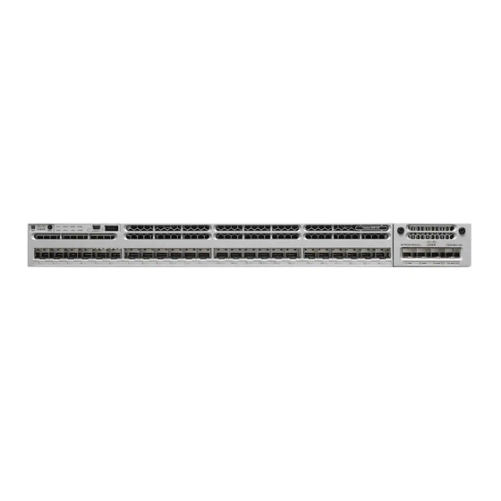
Network Modules, on page 11 PoE+ = Power over Ethernet plus (provides up to 30 W per port). UPOE = Universal Power Over Ethernet (provides up to 60 W Cisco UPOE per port) The WS-C3850-48XS switches do not support StackWise-480... - Page 21 • Mode button All of the switches have similar components. See the following illustrations for examples. Note The Catalyst 3850 switches might have slight cosmetic differences on the bezels. Figure 1: WS-C3850-48P-L Switch Front Panel Mode button USB mini-Type B...
-
Page 22: 10/100/1000 Ports
(UTP) cable. The 10BASE-T traffic can use Category 3 or Category 4 UTP cable. PoE, PoE+, and Cisco UPoE Ports The PoE+ and Cisco Universal Power Over Ethernet (Cisco UPoE) ports use the same connectors as described 10/100/1000 Port Connections, on page 49. -
Page 23: Sfp And Qsfp Module Slots
Product Overview SFP and QSFP Module Slots Depending on the installed power supply modules, each port can deliver up to 60 W of Cisco UPOE. See the Power Supply Modules, on page 25 for the power supply matrix that defines the available PoE, PoE+, and Cisco UPOE power per port. -
Page 24: Usb Type A Port
USB Type A Port If you use the USB mini-Type B console port, the Cisco Windows USB device driver must be installed on any PC connected to the console port (for operation with Microsoft Windows). Mac OS X or Linux do not require special drivers. -
Page 25: Network Modules
If you insert an SFP+ module in the 1 G network module, the SFP+ module does not operate, and the switch logs an error message. This is supported on the following switch models: Note • WS-C3850-24T/P/U • WS-C3850-48T/F/P/U • WS-C3850-12X48U • WS-C3850-24XU • WS-C3850-12S • WS-C3850-24S Catalyst 3850 Switch Hardware Installation Guide OL-26779-05... - Page 26 This is supported on the following switch models: • WS-C3850-12X48U • WS-C3850-24XU • WS-C3850-24XS C3850-NM-BLANK Insert this blank module when the switch has no uplink ports (this is required for sufficient air flow). Catalyst 3850 Switch Hardware Installation Guide OL-26779-05...
-
Page 27: Sfp And Sfp+ Modules
Catalyst WS-C3850-12XS and WS-C3850-24XS switch models support standard SFP+ modules. Use only Cisco SFP and SFP+ modules on the switch. For the latest information about supported SFP and SFP+ modules, refer to the Cisco Transceiver Modules Compatibility Information at http://www.cisco.com/en/US/products/hw/modules/ps5455/products_device_support_tables_list.html... - Page 28 This figure shows the switch LEDs and the Mode button that you use to select a port mode. STAT (status) USB mini-Type B console port LED DUPLX (duplex) SYST (system) SPEED ACTV (active) STACK S-PWR (StackPower) XPS = expandable power system. Only on switch models that support PoE. Catalyst 3850 Switch Hardware Installation Guide OL-26779-05...
- Page 29 USB mini-Type B console port LED STAT (status) SYST (system) DUPLX (duplex) ACTV (active) SPEED STACK S-PWR (StackPower) XPS = expandable power system. Figure 8: Switch Front Panel LEDs for the WS-C3850-48XS Switches Catalyst 3850 Switch Hardware Installation Guide OL-26779-05...
-
Page 30: Syst Led
The power supply in a switch has failed, and the XPS is providing power to that switch (redundancy has been allocated to this device). For information about the XPS 2200, see the Cisco eXpandable Power System 2200 Hardware Installation Guide on Cisco.com:... -
Page 31: Port Leds And Modes
Port is blocked by Spanning Tree Protocol (STP) and is not forwarding data. After a port is reconfigured, the port LED can be amber for up to 30 seconds as STP checks the switch for possible loops. Catalyst 3850 Switch Hardware Installation Guide OL-26779-05... -
Page 32: Speed
Switch is a standby member of a data stack and assumes active responsibilities if the current active switch fails. STACK (stack No stack member corresponding to that member number. member) Blinking green Stack member number. Green Member numbers of other stack member switches. Catalyst 3850 Switch Hardware Installation Guide OL-26779-05... -
Page 33: Usb Console Led
The USB is disabled. S-PWR LED Table 8: S-PWR LED Color Description StackPower cable is not connected, or the switch is in standalone mode. Green Each StackPower port is connected to another switch. Catalyst 3850 Switch Hardware Installation Guide OL-26779-05... -
Page 34: Actv Led
LEDs will be off. On switch 2, port 2 will blink green and the rest of the LEDs will be off. The same behavior will be seen with the remaining switches in the stack. Catalyst 3850 Switch Hardware Installation Guide OL-26779-05... -
Page 35: Poe Led
LED blinks green to show that this is switch 3 in the stack. PoE LED The PoE LED indicates the status of the PoE mode: either PoE, PoE+, or Cisco UPOE. Table 10: PoE LED Color Description PoE mode is not selected. None of the 10/100/1000 ports have been denied power or are in a fault condition. -
Page 36: Network Module Leds
Link is off due to a fault or because it has exceeded a limit set in the switch software. Caution Link faults occur when noncompliant cabling is connected to an SFP/SFP+ port. Use only standard-compliant cabling to connect to Cisco SFP/SFP+ ports. You must remove from the network any cable or device that causes a link fault. Amber Link for the SFP/SFP+ has been disabled. - Page 37 Product Overview Rear Panel Figure 11: Catalyst 3850 Switch Rear Panel Ground connector StackWise port connector CONSOLE (RJ-45 StackPower connector console port) MGMT (RJ-45 AC OK (input) status 10/100/1000 management port) RESET button PS OK (output) status Fan module Power supply modules...
- Page 38 AC OK (input) status 10/100/1000 management port) RESET button PS OK (output) status BEACON LED Power supply modules (AC power supply modules shown) Fan module Figure 13: WS-C3850-48XS Switches Switch Rear Panel Ground connector Fan module Catalyst 3850 Switch Hardware Installation Guide OL-26779-05...
-
Page 39: Rj-45 Console Port Led
• WS-C3850-48XS-F-S • WS-C3850-48XS-F-E Caution Use only approved cables, and connect only to similar Cisco equipment. Equipment might be damaged if connected to nonapproved Cisco cables or equipment. Power Supply Modules The switches are powered through one or two internal power supply modules. - Page 40 The switch can operate with either one or two active power supply modules or with power supplied by a stack. A Catalyst 3850 switch that is in a StackPower stack can operate with power supplied by other switches in the stack.
- Page 41 24-port Cisco UPOE switch 220 W 660 W 185 W 48-port Cisco UPOE switch 625 W Table 15: Switch Power Supply Requirements for PoE, PoE+, and Cisco UPoE PoE Option 24-Port Switch 48-Port Switch PoE (up to 15.4 per port) (1) 715 W...
-
Page 42: Fan Module
Product Overview Fan Module PoE Option 24-Port Switch 48-Port Switch Cisco UPoE (up to 60 W per port) (2) 1100 W These are the combinations of power supplies: • (1) 1100 W + (1) 715 W • (2) 1100 W... - Page 43 Figure 15: Airflow Patterns for the Catalyst 3850-24S-E and 3850-12S-E Switches Figure 16: Airflow Patterns for the Catalyst 3850-48XS Switches (using Power Supplies and Fans with Blue Handles) Catalyst 3850 Switch Hardware Installation Guide...
-
Page 44: Stackpower Connector
Product Overview StackPower Connector Figure 17: Airflow Patterns for the Catalyst 3850-48XS Switches (using Power Supplies and Fans with Red Handles) For information about installing a fan module and fan specifications, see the "Technical Specifications" chapter. StackPower Connector The switches have a StackPower connector for use with Cisco StackPower cables to configure a switch power stack that includes up to nine switches. -
Page 45: Rj-45 Console Port
Management Options • Cisco Network Assistant Cisco Network Assistant is a PC-based network management GUI application for LANs. You can use the GUI to configure and manage switch clusters or standalone switches. Cisco Network Assistant is available at no cost and can be downloaded from this URL: http://www.cisco.com/pcgi-bin/tablebuild.pl/... - Page 46 Product Overview Management Options Catalyst 3850 Switch Hardware Installation Guide OL-26779-05...
-
Page 47: Switch Installation
Before working on equipment that is connected to power lines, remove jewelry (including rings, necklaces, and watches). Metal objects will heat up when connected to power and ground and can cause serious burns or weld the metal object to the terminals. Statement 43 Catalyst 3850 Switch Hardware Installation Guide OL-26779-05... - Page 48 Only trained and qualified personnel should be allowed to install, replace, or service this equipment. Statement 1030 Warning Ultimate disposal of this product should be handled according to all national laws and regulations. Statement 1040 Catalyst 3850 Switch Hardware Installation Guide OL-26779-05...
-
Page 49: Installation Guidelines
328 feet (100 meters). • Temperature around the unit does not exceed 113°F (45°C). If the switch is installed in a closed or multirack assembly, the temperature around it might be greater than normal room temperature. Catalyst 3850 Switch Hardware Installation Guide OL-26779-05... -
Page 50: Box Contents
After a successful POST, disconnect the power cord from the switch. Install the switch in a rack, on a table, or on a shelf as described in Installing the Switch, on page Planning a Switch Data Stack Catalyst 3850 switches can share bandwidth by using data stacking. Note The following switch models do not support StackWise-480: • WS-C3850-48XS-S •... -
Page 51: Switch Stacking And Power Stacking Guidelines
4 ASIC chips, and the maximum number of ASIC chips per stack cannot exceed 32. • If you set up a stack that contains the above switches and other Catalyst 3850 switches, ensure that the maximum number of ASIC chips is 32. -
Page 52: Data Stack Cabling Configurations
Figure 20: Example of a Data Stack with Full Bandwidth Connections This figure shows an example of a stack of switches with incomplete StackWise cabling connections. This stack provides only half bandwidth and does not have redundant connections. Catalyst 3850 Switch Hardware Installation Guide OL-26779-05... -
Page 53: Power-On Sequence For Switch Stacks
After 2 minutes, power on the other switches in the stack. If you have no preference as to which switch becomes the active switch, power on all Catalyst 3850 Switch Hardware Installation Guide OL-26779-05... -
Page 54: Planning A Stackpower Stack
Following the failure of a power supply, the StackPower mode becomes power sharing. Note Power-sharing mode is the recommended configuration for Cisco Catalyst 3850 Series Switches . For general concepts and management procedures for switch power stacks, see the Software Configuration Guide on Cisco.com. -
Page 55: Stackpower Cabling Configurations
• Length of cable. Depending on the configurations that you have, you might need different-sized cables. If you do not specify the length of the StackPower cable, the 0.3 meter cable is supplied. If you need the 1.5 meter cable, you can order it from your Cisco supplier. For cable part numbers, see StackPower Connector, on page 30. -
Page 56: Stackpower Partitioning Examples
Figure 26: StackPower Star Topology StackPower Partitioning Examples These figures show StackPower stacks of switches with failover conditions. In this figure, the StackPower cable 2 is faulty. Therefore, this stack does not provide redundancy. Catalyst 3850 Switch Hardware Installation Guide OL-26779-05... -
Page 57: Installing The Switch
• When mounting this unit in a partially filled rack, load the rack from the bottom to the top with the heaviest component at the bottom of the rack. • If the rack is provided with stabilizing devices, install the stabilizers before mounting or servicing the unit in the rack. Statement 1006 Catalyst 3850 Switch Hardware Installation Guide OL-26779-05... -
Page 58: Attaching The Rack-Mount Brackets
Switch Installation Attaching the Rack-Mount Brackets Figure 29: Rack-Mounting Brackets This figure shows the standard 19-inch brackets and other optional mounting brackets. You can order the optional brackets from your Cisco sales representative. 19-inch brackets 23-inch brackets (C3850-RACK-KIT=) (C3850-RACK-KIT=) Extension rails and... - Page 59 Switch Installation Attaching the Rack-Mount Brackets Figure 30: Attaching Brackets for 19-inch Racks Rear-mounting position Front-mounting position Number-8 Phillips flat-head screws Catalyst 3850 Switch Hardware Installation Guide OL-26779-05...
-
Page 60: Mounting The Switch A Rack
Step 2 Use the black Phillips machine screw to attach the cable guide to the left or right bracket. Phillips machine screw, Front-mounting position black Cable guide Number-12 or number-10 Phillips machine screws Catalyst 3850 Switch Hardware Installation Guide OL-26779-05... -
Page 61: Installing The Switch On A Table Or Shelf
Connect the cable to the StackWise port on the switch rear panel. Align the connector and connect the StackWise cable to the StackWise port on the switch rear panel and finger-tighten the screws (clockwise direction). Make sure the Cisco logo is on the top side of the connector as shown in the figure. Step 3 Connect the other end of the cable to the port on the other switch and finger-tighten the screws. -
Page 62: Connecting To The Stackpower Ports
Planning a Switch Data Stack, on page 36. Always use a Cisco-approved StackWise cable to connect the switches. To prevent misconfiguration, the StackPower ports on the switch are keyed and have colored bands that match the keying and bands on the StackPower cable connectors. -
Page 63: Installing A Network Module In The Switch
• 10/100/1000 Port Connections, on page 49 • PoE+ and Cisco UPOE Port Connections, on page 50 10/100/1000 Port Connections The switch 10/100/1000 port configuration changes to operate at the speed of the attached device. If the attached ports do not support autonegotiation, you can manually set the speed and duplex parameters. -
Page 64: Auto-Mdix Connections
Mode button, which might cause the switch to erase its startup configuration and reboot. See this field notice for more information: http://www.cisco.com/c/en/us/support/ docs/field-notices/636/fn63697.html This issue does not occur if you are using Cisco IOS XE Release 3E or later releases. Catalyst 3850 Switch Hardware Installation Guide OL-26779-05... -
Page 65: Where To Go Next
PoE inline power supports devices compliant with the IEEE 802.3af standard, as well as prestandard Cisco IP Phones and Cisco Aironet Access Points. Each port can deliver up to 15.4 W of PoE. PoE+ inline power supports devices compliant with the IEEE 802.3at standard, by delivering up to 30 W of PoE+ power per port to all switch ports. - Page 66 Switch Installation Where to Go Next Catalyst 3850 Switch Hardware Installation Guide OL-26779-05...
-
Page 67: Installing A Network Module
If you insert an SFP+ module in the 1 G network module, the SFP+ module does not operate, and the switch logs an error message. Note This is supported on the following switch models: • WS-C3850-24T/P/U • WS-C3850-48T/F/P/U • WS-C3850-12X48U • WS-C3850-24XU • WS-C3850-12S • WS-C3850-24S Catalyst 3850 Switch Hardware Installation Guide OL-26779-05... - Page 68 This is supported on the following switch models: • WS-C3850-12X48U • WS-C3850-24XU • WS-C3850-24XS C3850-NM-BLANK Insert this blank module when the switch has no uplink ports (this is required for sufficient air flow). Catalyst 3850 Switch Hardware Installation Guide OL-26779-05...
- Page 69 Figure 34: C3850-NM-4-1G Network Module Captive screws LEDs 1 G Ethernet SFP slots Figure 35: C3850-NM-2-10G Network Module Captive screws 1 G Ethernet SFP slots 1 G or 10 G Ethernet LEDs SFP+ slots Catalyst 3850 Switch Hardware Installation Guide OL-26779-05...
- Page 70 You must fasten the screw completely to secure the module, and loosen the screw first so that the module may be removed. 10 G or 1 G SFP+ slots Catalyst 3850 Switch Hardware Installation Guide OL-26779-05...
-
Page 71: Network Module Leds
Figure 38: C3850-NM-2-40G Network Module Captive screws LEDs 40 G QSFP+ slots Figure 39: Blank Network Module Blank module Captive screws Network Module LEDs Figure 40: Network Module LEDs G1 LED G3 LED Catalyst 3850 Switch Hardware Installation Guide OL-26779-05... -
Page 72: Installing A Network Module In The Switch
Safety Warnings This section includes the installation cautions and warnings. Translations of the safety warnings appear in the Regulatory Compliance and Safety Information for the Catalyst 3850 Switches on Cisco.com: http://www.cisco.com/go/cat3850_hw Read this section before you install a network module. -
Page 73: Equipment That You Need
• Do not remove the blank module from the slot unless you are installing an SFP or SFP+ module. Either a module or a dust plug must be in the slot at all times. Catalyst 3850 Switch Hardware Installation Guide OL-26779-05... - Page 74 Position the module face up to install it in the module slot. Slide the module into the slot until the back of the module faceplate is flush with the switch faceplate. Fasten the captive screws to secure the network module in place. Figure 41: Installing the Network Module in the Switch Catalyst 3850 Switch Hardware Installation Guide OL-26779-05...
-
Page 75: Network Module Port Configurations
TenGigabitEthernet1/1/4, even when you are operating them as 1 G using SFPs. Only four interfaces are valid; the other four should not be used even though they still show up in the CLI. Table 21: C3850-NM-4-10G Module Interface Action GigabitEthernet1/1/1 Disregard GigabitEthernet1/1/2 Disregard Catalyst 3850 Switch Hardware Installation Guide OL-26779-05... -
Page 76: C3850-Nm-2-10G Module
All ports in the C3850-NM-8-10G module default to 10 G and should be configured as TenGigabitEthernet1/1/1 through TenGigabitEthernet1/1/8, even when you are operating them as 1 G using SFP. Table 23: C3850-NM-8-10G Module Interface Action TenGigabitEthernet1/1/1 Configure this interface TenGigabitEthernet1/1/2 Configure this interface Catalyst 3850 Switch Hardware Installation Guide OL-26779-05... -
Page 77: C3850-Nm-2-40G Module
Disregard TenGigabitEthernet1/1/7 Disregard TenGigabitEthernet1/1/8 Disregard If you use a 4x10G breakout cable, the ports default to 10 G interfaces. Table 25: C3850-NM-2-40G Module with 4x10G breakout cable Interface Action FortyGigabitEthernet1/1/1 Disregard FortyGigabitEthernet1/1/2 Disregard Catalyst 3850 Switch Hardware Installation Guide OL-26779-05... -
Page 78: Removing A Network Module
Step 2 Disconnect the cables from the SFP modules. Step 3 Remove the SFP modules from the network module. Step 4 Loosen the captive screws that hold the network module in place. Catalyst 3850 Switch Hardware Installation Guide OL-26779-05... -
Page 79: Installing Sfp And Sfp+ Modules
WS-C3850-24XS switch models support standard SFP+ modules. See the switch release notes on Cisco.com for the list of supported SFP and SFP+ modules. Use only supported SFP modules on the switch. For the latest information about supported SFP and SFP+ modules, refer to the Cisco Transceiver Modules Compatibility Information at http://www.cisco.com/en/US/products/hw/modules/ps5455/products_device_support_tables_list.html... -
Page 80: Removing Sfp And Sfp+ Modules
Step 5 Grasp the SFP/SFP+ module, and carefully remove it from the slot. Step 6 Place the SFP/SFP+ module in an antistatic bag or other protective environment. Catalyst 3850 Switch Hardware Installation Guide OL-26779-05... -
Page 81: Finding The Network Module Serial Number
Finding the Network Module Serial Number Finding the Network Module Serial Number If you contact Cisco Technical Assistance regarding a network module, you need to know its serial number. Figure 44: Network Module Serial Number Location Catalyst 3850 Switch Hardware Installation Guide... - Page 82 Installing a Network Module Finding the Network Module Serial Number Catalyst 3850 Switch Hardware Installation Guide OL-26779-05...
-
Page 83: Power Supply Installation
Finding the Power Supply Module Serial Number, on page 80 Power Supply Module Overview The switch operates with either one or two active power supply modules. A Catalyst 3850 switch that is part of a StackPower stack operates with power supplied by other stack switches. - Page 84 Figure 45: 1100-W AC Power Supply 1100-W AC power supply Release latch module AC OK LED Power cord retainer PS OK LED Keying feature AC power cord connector Figure 46: 715-W AC Power Supply Catalyst 3850 Switch Hardware Installation Guide OL-26779-05...
- Page 85 AC power cord connector Figure 48: 440-W DC Power Supply 440-W DC power supply Grounding terminal module AC OK LED Release latch PS OK LED Extraction handle Input power terminals Terminal block safety (positive polarity) cover Catalyst 3850 Switch Hardware Installation Guide OL-26779-05...
-
Page 86: Installation Guidelines
• The switch is in StackPower mode and sufficient power is available. • The switch is powered by other switches in a power stack, and no active backup is in progress. Catalyst 3850 Switch Hardware Installation Guide OL-26779-05... - Page 87 Only trained and qualified personnel should be allowed to install, replace, or service this equipment. Statement 1030 Warning If a Cisco external power system is not connected to the switch, install the provided connector cover on the back of the switch. Statement 386...
-
Page 88: Installing Or Replacing An Ac Power Supply
Figure 50: Inserting the AC-Power Supply in the Catalyst WS-C3850 Switch Figure 51: Inserting the AC-Power Supply in the Catalyst WS-C3850-48XS Switch Step 6 (Optional) Make a loop in the power cord and thread it through the power cord retainer. Catalyst 3850 Switch Hardware Installation Guide OL-26779-05... -
Page 89: Installing A Dc Power Supply
This product relies on the building's installation for short-circuit (overcurrent) protection. Ensure that the protective device is rated not greater than: 20 A. Statement 1005 Warning A readily accessible two-poled disconnect device must be incorporated in the fixed wiring. Statement 1022 Catalyst 3850 Switch Hardware Installation Guide OL-26779-05... -
Page 90: Equipment That You Need
Contact the appropriate electrical inspection authority or an electrician if you are uncertain that suitable grounding is available. Statement 1024 Warning When installing or replacing the unit, the ground connection must always be made first and disconnected last. Statement 1046 Catalyst 3850 Switch Hardware Installation Guide OL-26779-05... - Page 91 Figure 55: Crimping the Ground Lug Step 5 Use the ground screw to attach the single-ground lug to the switch rear panel. Use two ground screws to attach the dual-hole lug to the switch rear panel. Catalyst 3850 Switch Hardware Installation Guide OL-26779-05...
-
Page 92: Installing The Dc Power Supply In The Switch
Insert the power supply in the power-supply slot, and gently push it into the slot. When correctly installed, the DC power supply (excluding the extraction handle) is flush with the switch rear panel. Catalyst 3850 Switch Hardware Installation Guide OL-26779-05... -
Page 93: Wiring The Dc Input Power Source
Connect the ground wire to a grounded metal rack or to earth ground if the switch is not in a grounded rack. Catalyst 3850 Switch Hardware Installation Guide OL-26779-05... -
Page 94: Finding The Power Supply Module Serial Number
Finding the Power Supply Module Serial Number If you contact Cisco Technical Assistance regarding a power supply module, you need to know the serial number. See the following illustrations to find the serial number. You can also use the CLI to find out the serial number. - Page 95 Finding the Power Supply Module Serial Number Figure 62: 715-W and 350-W AC Power Supply Serial Number Figure 63: 440-W DC Power Supply Serial Number Figure 64: 750-W AC Power Supply Serial Number Catalyst 3850 Switch Hardware Installation Guide OL-26779-05...
- Page 96 Power Supply Installation Finding the Power Supply Module Serial Number Figure 65: 750-W AC Power Supply Serial Number Figure 66: 750-W DC Power Supply Serial Number Catalyst 3850 Switch Hardware Installation Guide OL-26779-05...
-
Page 97: Installing The Fan
Figure 67: Fan Module for WS-C3850 Switches Fan LED Retainer clip Exhaust vent Extraction handles Note The WS-C3850 switches require three fans for proper cooling. Catalyst 3850 Switch Hardware Installation Guide OL-26779-05... -
Page 98: Installation Guidelines
• The switch supports hot swapping of the fan module. You can remove and replace the module without interrupting normal switch operation. Warning Only trained and qualified personnel should be allowed to install, replace, or service this equipment. Statement 1030 Catalyst 3850 Switch Hardware Installation Guide OL-26779-05... -
Page 99: Installing A Fan Module
Ensure that the fans are inserted correctly to match the corresponding power supplies. Fans with blue handles correspond to power supplies with blue handles, and fans with red handles correspond to power supplies with red handles. Catalyst 3850 Switch Hardware Installation Guide OL-26779-05... -
Page 100: Finding The Fan Module Serial Number
Finding the Fan Module Serial Number Finding the Fan Module Serial Number If you contact Cisco Technical Assistance regarding a fan module, you need to know the fan module serial number. See the following illustration to find the serial number. -
Page 101: Configuring The Switch
Connect one end of an ethernet cable to one of the uplink (non-management) ports on the active supervisor and the other end of the ethernet cable to the host (PC). Step 3 Set up your PC as a DHCP client, to obtain the IP address of the switch automatically. Catalyst 3850 Switch Hardware Installation Guide OL-26779-05... -
Page 102: Creating User Accounts
Step 1 Log on using the default username and password provided with the device. The default username is cisco; the default password is the serial number of the switch chassis. Step 2 Set a password of up to 25 alphanumeric characters. The username password combination you set gives you privilege 15 access. - Page 103 Configuring the Switch Creating User Accounts Figure 72: Create Account Catalyst 3850 Switch Hardware Installation Guide OL-26779-05...
-
Page 104: Choosing Setup Options
Choose the date and time settings for your device. To synchronize your device with a valid outside timing mechanism, such as an NTP clock source, choose Automatic, or choose Manual to set it yourself. Catalyst 3850 Switch Hardware Installation Guide OL-26779-05... - Page 105 If you did not select Wired Network, in the earlier step, continue to the next screen to verify your configuration on the Day 0 Config Summary screen, and click Finish. To automatically configure your device based on a site profile, click Setup Options, and select Wired Network. Catalyst 3850 Switch Hardware Installation Guide OL-26779-05...
-
Page 106: Configuring Your Device Based On A Site Profile
To ease your configuration tasks and save time, choose a site profile based on where your device may be installed and managed in your network. Based on the site profile you choose, your device is automatically Catalyst 3850 Switch Hardware Installation Guide OL-26779-05... - Page 107 Configuring the Switch Configuring Your Device Based on a Site Profile configured according to Cisco best practices. You can easily modify this default configuration, from the corresponding detailed configuration screens. Choosing a site profile as part of Quick Setup allows you to configure your device based on the business needs of your enterprise.
- Page 108 VLANs. VLANs. Downlink Interfaces Downlink ports Downlink ports Downlink ports configured in Access configured in Access configured in Access mode mode mode Port-channel Not configured Port-channel to Port-channel to distribution created distribution created Catalyst 3850 Switch Hardware Installation Guide OL-26779-05...
- Page 109 Configuring the Switch Configuring Your Device Based on a Site Profile Figure 75: Site Profile - Access Switches Catalyst 3850 Switch Hardware Installation Guide OL-26779-05...
- Page 110 The hostname or device The hostname or device The hostname or device name you provided as part name you provided as part name you provided as part of Quick Setup of Quick Setup of Quick Setup Catalyst 3850 Switch Hardware Installation Guide OL-26779-05...
- Page 111 Trunk mode configured in Trunk mode configured in Trunk mode Port-channel Port-channel to core Port-channel to core or Port-channel to core or created access created distribution created Catalyst 3850 Switch Hardware Installation Guide OL-26779-05...
- Page 112 Configuring the Switch Configuring Your Device Based on a Site Profile Figure 77: Site Profile - Distribution Switches Catalyst 3850 Switch Hardware Installation Guide OL-26779-05...
- Page 113 (with ECMP Peer and Port Channel Downlink) Hostname The hostname or device name you The hostname or device name you provided as part of Quick Setup provided as part of Quick Setup UDLD Enabled Enabled Catalyst 3850 Switch Hardware Installation Guide OL-26779-05...
- Page 114 Selected uplink ports connect to MAN/WAN device MAN/WAN device Downlink Interfaces Downlink connections to access Downlink connections to switches distribution switches Cross-connect Interfaces Selected ports connect to other core Selected ports connect to other core switches switches Catalyst 3850 Switch Hardware Installation Guide OL-26779-05...
-
Page 115: Configuring Switch Wide Settings
Figure 79: Site Profile - Core Switches Configuring Switch Wide Settings Configuring VLAN Settings Procedure Step 1 In the VLAN Configuration section, you can configure both data and voice VLANs. Type a name for your data VLAN. Catalyst 3850 Switch Hardware Installation Guide OL-26779-05... -
Page 116: Configure Stp Settings
RPVST is the default STP mode configured on your device. You can change it to PVST from the STP Mode drop-down list. Step 2 To change a bridge priority number from the default value 32748, change Bridge Priority to Yes and choose a priority number from the drop-down list. Catalyst 3850 Switch Hardware Installation Guide OL-26779-05... -
Page 117: Configuring Dhcp, Ntp, Dns And Snmp Settings
In the Domain Details section, enter a domain name that the software uses to complete unqualified hostnames. Step 2 Type an IP address to identify the DNS server. This server is used for name and address resolution on your device. Catalyst 3850 Switch Hardware Installation Guide OL-26779-05... - Page 118 In the Management Details section, type an IP address to identify the SNMP server. SNMPv1, SNMPv2, and SNMPv3 are supported on your device. Step 7 Specify the SNMP community string to permit access to the SNMP protocol. Figure 81: DHCP, NTP, DNS and SNMP Settings Catalyst 3850 Switch Hardware Installation Guide OL-26779-05...
-
Page 119: Configuring Port Settings
Choose an option from the Select Switch drop-down list. Step 3 Make selections from the Available list of interfaces based on how you want to enable them and move them to the Enabled list. Catalyst 3850 Switch Hardware Installation Guide OL-26779-05... - Page 120 Configuring the Switch Configuring Port Settings Figure 82: Port Settings What to do next • Click Day 0 Config Summary to verify your setup. • Click Finish. Catalyst 3850 Switch Hardware Installation Guide OL-26779-05...
-
Page 121: Configuring The Switch Using The Cli
You can access the CLI on a configured or unconfigured switch by connecting the RJ-45 console port or USB console port of the switch to your PC or workstation and accessing the switch through a terminal emulation program. Catalyst 3850 Switch Hardware Installation Guide OL-26779-05... -
Page 122: Connecting The Rj-45 Console Port
Step 1 If you are connecting the switch USB console port to a Windows-based PC for the first time, install the USB driver. See Installing the Cisco Microsoft Windows USB Device Driver, on page 111. Note USB Type A port on the switch provides file system support and is NOT a console port. See USB Type A Port section. - Page 123 Configuring the Switch Connecting the USB Console Port Figure 84: Connecting the USB Console Cable to the Switch Figure 85: Connecting the USB Console Cable to the Switch Catalyst 3850 Switch Hardware Installation Guide OL-26779-05...
- Page 124 Power on the switch as described in the switch getting started guide. Step 6 The PC or terminal displays the bootloader sequence. Press Enter to display the setup prompt. Follow the steps in the Setup program. Catalyst 3850 Switch Hardware Installation Guide OL-26779-05...
-
Page 125: Installing The Cisco Microsoft Windows Usb Device Driver
Installing the Cisco Microsoft Windows XP USB Driver Procedure Step 1 Obtain the Cisco USB console driver file from the Cisco.com web site and unzip it. You can download the driver file from the Cisco.com site for downloading the switch software. Note Step 2 If using 32-bit Windows XP, double-click the setup.exe file in the Windows_32 folder. -
Page 126: Installing The Cisco Microsoft Windows Vista And Windows 7 Usb Driver
Installing the Cisco Microsoft Windows Vista and Windows 7 USB Driver Procedure Step 1 Obtain the Cisco USB console driver file from the Cisco.com web site and unzip it. You can download the driver file from the Cisco.com site for downloading the switch software. Note Step 2 If using 32-bit Windows Vista or Windows 7, double-click the setup.exe file in the Windows_32 folder. -
Page 127: Uninstalling The Cisco Microsoft Windows Vista And Windows 7 Usb Driver
Configuring the Switch Uninstalling the Cisco Microsoft Windows Vista and Windows 7 USB Driver Procedure Step 1 Click Start > Control Panel > Add or Remove Programs. Step 2 Scroll to Cisco Virtual Com and click Remove. Step 3 When the Program Maintenance window appears, select the Remove radio button. Click Next. - Page 128 Configuring the Switch Uninstalling the Cisco Microsoft Windows Vista and Windows 7 USB Driver Catalyst 3850 Switch Hardware Installation Guide OL-26779-05...
-
Page 129: Troubleshooting
You can also get statistics from Device Manager, from the CLI, or from an SNMP workstation. Switch POST Results POST failures are usually fatal. Contact your Cisco technical support representative if your switch does not pass POST. Switch LEDs If you have physical access to the switch, look at the port LEDs for troubleshooting information about the switch. -
Page 130: Ethernet And Fiber-Optic Cables
• Use the show interfaces privileged EXEC command to see if the port is in error-disabled, disabled, or shutdown. Reenable the port if necessary. • Verify that the power supply installed in the switch meets the power requirements of your connected devices. Catalyst 3850 Switch Hardware Installation Guide OL-26779-05... -
Page 131: Sfp And Sfp+ Module
SFP and SFP+ Module Use only Cisco SFP or SFP+ modules in the switch. Each Cisco module has an internal serial EEPROM that is encoded with security information. This encoding provides a way for Cisco to identify and validate that the module meets the requirements for the switch. -
Page 132: Switch Performance
Express Setup mode, you can clear the configured IP address. The switch returns to the factory default settings. Note This procedure clears the IP address and all configuration information stored on the switch. Do not follow this procedure unless you want to completely reconfigure the switch. Catalyst 3850 Switch Hardware Installation Guide OL-26779-05... -
Page 133: Replacing A Failed Data Stack Member
Replacing a Failed Data Stack Member Procedure Step 1 If you are using Cisco IOS XE Release 3E or later releases, enter the erase startup-config privileged EXEC command to clear the contents of your startup configuration. Step 2 Press and hold the Mode button. The switch LEDs blink after about 2 seconds. If the switch is not configured, the LEDs above the Mode button turn green. - Page 134 Troubleshooting Replacing a Failed Data Stack Member Catalyst 3850 Switch Hardware Installation Guide OL-26779-05...
-
Page 135: Appendix A Technical Specifications
Operating temperature AC power supply: 23 to 113°F (–5 to 45°C) DC power supply: 23 to 131°F (–5 to 55°C) Storage temperature –40 to 158°F (–40 to 70°C) Relative humidity 10 to 95% (noncondensing) Catalyst 3850 Switch Hardware Installation Guide OL-26779-05... - Page 136 2.8 lb (1.3 kg) PWR-C1-350WAC 2.4 lb (1.1 kg) PWR-C1-440WDC= 2.6 lb (1.2 kg) PWR-C3-750WAC-R 3.7 lb (1.68 kg) PWR-C3-750WAC-F 3.7 lb (1.68 kg) PWR-C3-750WDC-R 3.7 lb (1.68 kg) PWR-C3-750WDC-F 3.7 lb (1.68 kg) Catalyst 3850 Switch Hardware Installation Guide OL-26779-05...
-
Page 137: Specifications For The Power Supplies, Switches, And Fan
VAC(autoranging) 50-60 Hz • PWR-C1-350WAC: 350 W, 100 to 240 VAC(autoranging) 50-60 Hz • PWR-C3-750WAC-F: 750 W, 90 to 264 VAC(autoranging) 50-60 Hz • PWR-C3-750WAC-F: 750 W, 90 to 264 VAC(autoranging) 50-60 Hz Catalyst 3850 Switch Hardware Installation Guide OL-26779-05... - Page 138 The BTU ratings are based on 100 VAC for the 350-W and 715-W power supplies and 115 VAC for the 1100-W power supply. Table 36: Power Specifications for DC-Power Power Requirements • PWR-C1-440WDC: 440 W Maximum output power • PWR-C3-750WDC-R: 750 W • PWR-C3-750WDC-F: 750 W Catalyst 3850 Switch Hardware Installation Guide OL-26779-05...
- Page 139 The BTU ratings are based on –36 VDC. Table 37: Fan Module Environmental and Physical Specifications for Catalyst WS-C3850 Switch Models Environmental Ranges 23 to 176°F (–5 to 80°C) Operating temperature Catalyst 3850 Switch Hardware Installation Guide OL-26779-05...
- Page 140 –50 to 6500 feet (–16 to 1981 meters) Physical Specification 2.25 x 7.00 x 8.50 in (5.72 x 17.78 x 21.59 cm) Dimensions (H x D x W) Weight 0.7 lb (0.32 kg) Catalyst 3850 Switch Hardware Installation Guide OL-26779-05...
-
Page 141: Appendix B Connector And Cable Specifications
Cables and Adapters, on page 129 Connector Specifications 10/100/1000 Ports (Including PoE) All 10/100/1000 ports use standard RJ-45 connectors and Ethernet pinouts. Figure 86: 10/100/1000 Port Pinouts SFP Module Connectors Figure 87: Duplex LC Cable Connector Catalyst 3850 Switch Hardware Installation Guide OL-26779-05... -
Page 142: Console Port
The USB console port uses a USB Type A to 5-pin mini-Type B cable. The USB Type A-to-USB mini-Type B cable is not supplied. You can order an accessory kit (part number 800-33434) that contains this cable. Catalyst 3850 Switch Hardware Installation Guide OL-26779-05... -
Page 143: Cables And Adapters
Cables and Adapters StackWise Cables You can order these StackWise cables (nonhalogen) from your Cisco sales representative: • STACK-T1-50CM= (0.5-meter cable) • STACK-T1-1M= (1-meter cable) • STACK-T1-3M= (3-meter cable) - Page 144 Cisco QSFP to SFP or SFP+ Adapter Cisco QSFP to SFP or SFP+ Adapter (QSA) is a pluggable adapter that converts a QSFP port in to an SFP or SFP+ port. You can connect one of the following SFP+ or SFP module or an SFP+ copper.
- Page 145 The RS-232 console port uses an 8-pin RJ-45 connector. Use an RJ-45-to-DB-9 adapter cable to connect the switch console port to a console PC. You need to provide a RJ-45-to-DB-25 female DTE adapter to connect the switch console port to a terminal. Catalyst 3850 Switch Hardware Installation Guide OL-26779-05...
- Page 146 Switch Console Port (DTE) RJ-45-to-DB-9 Terminal Adapter Console Device Signal DB-9 Pin Signal Table 41: Console Port Signaling with a DB-25 Adapter Switch Console Port (DTE) RJ-45-to-DB-25 Terminal Adapter Console Device Signal DB-25 Pin Signal Catalyst 3850 Switch Hardware Installation Guide OL-26779-05...
Need help?
Do you have a question about the Catalyst 3850 and is the answer not in the manual?
Questions and answers