Table of Contents
Advertisement
Questo manuale d'istruzione è fornito da trovaprezzi.it. Scopri tutte le offerte per
NM-2-10G
o cerca il tuo prodotto tra le
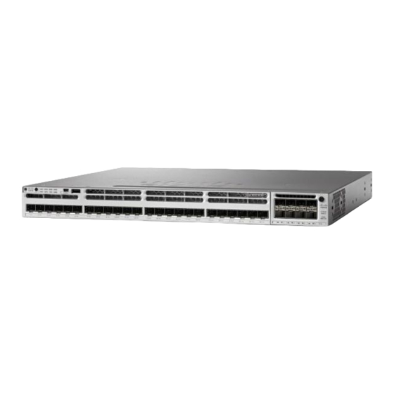
Catalyst 3850 Switch Hardware Installation Guide
First Published: 2013-01-21
Last Modified: 2015-09-22
Americas Headquarters
Cisco Systems, Inc.
170 West Tasman Drive
San Jose, CA 95134-1706
USA
http://www.cisco.com
Tel: 408 526-4000
800 553-NETS (6387)
Fax: 408 527-0883
Text Part Number: OL-26779-05
migliori offerte di Modem e Router
Cisco C3850-
Advertisement
Table of Contents

Related Manuals for Cisco Catalyst C3850 Series


Summary of Contents for Cisco Catalyst C3850 Series
- Page 1 Modem e Router Catalyst 3850 Switch Hardware Installation Guide First Published: 2013-01-21 Last Modified: 2015-09-22 Americas Headquarters Cisco Systems, Inc. 170 West Tasman Drive San Jose, CA 95134-1706 http://www.cisco.com Tel: 408 526-4000 800 553-NETS (6387)
-
Page 2: Table Of Contents
C H A P T E R 1 Product Overview Switch Models Front Panel 10/100/1000 Ports PoE, PoE+, and Cisco UPoE Ports SFP and QSFP Module Slots Management Ports USB Type A Port Network Modules SFP and SFP+ Modules... - Page 3 Contents Network Module LEDs Rear Panel RJ-45 Console Port LED StackWise Ports Power Supply Modules Fan Module StackPower Connector Ethernet Management Port RJ-45 Console Port Management Options C H A P T E R 2 Switch Installation Preparing for Installation Safety Warnings Installation Guidelines Box Contents...
- Page 4 Contents Connecting to the StackWise Ports Connecting to the StackPower Ports Installing a Network Module in the Switch Installing and Removing Cisco Pluggable Transceiver Modules Connecting Devices to the Ethernet Ports 10/100/1000/Multigigabit Ethernet Port Connections Auto-MDIX Connections PoE+ and Cisco UPOE Port Connections...
- Page 5 Accessing the CLI Through the Console Port Connecting the RJ-45 Console Port Connecting the USB Console Port Installing the Cisco Microsoft Windows USB Device Driver Installing the Cisco Microsoft Windows 7 USB Driver Uninstalling the Cisco Microsoft Windows USB Driver...
- Page 6 Contents C H A P T E R 7 Troubleshooting Diagnosing Problems Switch POST Results Switch LEDs Switch Connections Bad or Damaged Cable Ethernet and Fiber-Optic Cables Link Status 10/100/1000 Port Connections 10/100/1000 PoE+ Port Connections SFP and SFP+ Module Interface Settings Ping End Device Spanning Tree Loops...
- Page 7 Contents Cisco QSFP to SFP or SFP+ Adapter Cable Pinouts Console Port Adapter Pinouts Catalyst 3850 Switch Hardware Installation Guide OL-26779-05...
- Page 8 Contents Catalyst 3850 Switch Hardware Installation Guide viii OL-26779-05...
- Page 9 Cisco has more than 200 offices worldwide. Addresses and phone numbers are listed on the Cisco website at www.cisco.com/go/offices. Cisco and the Cisco logo are trademarks or registered trademarks of Cisco and/or its affiliates in the U.S. and other countries. To view a list of Cisco trademarks, go to this URL: www.cisco.com...
-
Page 11: Preface
Preface • Document Conventions , on page xi • Related Documentation, on page xiii • Obtaining Documentation and Submitting a Service Request, on page xiii Document Conventions This document uses the following conventions: Convention Description ^ or Ctrl Both the ^ symbol and Ctrl represent the Control (Ctrl) key on a keyboard. For example, the key combination ^D or Ctrl-D means that you hold down the Control key while you press the D key. - Page 12 Preface Preface Convention Description [x {y | z}] Nested set of square brackets or braces indicate optional or required choices within optional or required elements. Braces and a vertical bar within square brackets indicate a required choice within an optional element. string A nonquoted set of characters.
-
Page 13: Related Documentation
Obtaining Documentation and Submitting a Service Request For information on obtaining documentation, submitting a service request, and gathering additional information, see the monthly What's New in Cisco Product Documentation, which also lists all new and revised Cisco technical documentation, at: http://www.cisco.com/c/en/us/td/docs/general/whatsnew/whatsnew.html... - Page 14 Preface Obtaining Documentation and Submitting a Service Request Catalyst 3850 Switch Hardware Installation Guide OL-26779-05...
-
Page 15: Product Overview
C H A P T E R Product Overview The Catalyst 3850 family of switches are Ethernet switches to which you can connect devices such as Cisco IP Phones, Cisco Wireless Access Points, workstations, and other network devices such as servers, routers, and other switches. - Page 16 WS-C3850-48F-L LAN Base Stackable 48 10/100/1000 PoE+ ports, 1 network module slot, 1100 W power supply WS-C3850-24U-L LAN Base Stackable 24 10/100/1000 Cisco UPOE ports, 1 network module slot, 1100 W power supply WS-C3850-48U-L LAN Base Stackable 48 10/100/1000 Cisco...
- Page 17 Product Overview Switch Models Switch Model Supported Software Image Description WS-C3850-48PW-S IP Base Catalyst 3850 48-port PoE IP Base with 5 access points license WS-C3850-12S-S IP Base Stackable 12 SFP module slots, 1 network module slot, 350 W power supply WS-C3850-24S-S IP Base Stackable 24 SFP module slots, 1...
- Page 18 Product Overview Switch Models Switch Model Supported Software Image Description WS-C3850-48XS-F-S IP Base Catalyst 3850 switch with SFP+ transceivers, 48 ports that support up to 10 G, and 4 QSFP ports that support up to 40 G. 750 W power supply.
- Page 19 Product Overview Switch Models Switch Model Supported Software Image Description WS-C3850-24U-E IP Services Stackable 24 10/100/1000 Cisco UPOE ports, 1 network module slot, 1100 W power supply WS-C3850-48U-E IP Services Stackable 48 10/100/1000 Cisco UPOE ports, 1 network module slot, 1100 W power supply...
-
Page 20: Front Panel
Network Modules, on page 11 PoE+ = Power over Ethernet plus (provides up to 30 W per port). UPOE = Universal Power Over Ethernet (provides up to 60 W Cisco UPOE per port) The WS-C3850-48XS switches do not support StackWise-480... - Page 21 Product Overview Front Panel • LEDs • Mode button All of the switches have similar components. See the following illustrations for examples. Note The Catalyst 3850 switches might have slight cosmetic differences on the bezels. Figure 1: WS-C3850-48P-L Switch Front Panel Mode button USB mini-Type B (console) port...
-
Page 22: 10/100/1000 Ports
Category 3 or Category 4 UTP cable. PoE, PoE+, and Cisco UPoE Ports The PoE+ and Cisco Universal Power Over Ethernet (Cisco UPoE) ports use the same connectors as described 10/100/1000/Multigigabit Ethernet Port Connections, on page 49. They provide: •... -
Page 23: Sfp And Qsfp Module Slots
Product Overview SFP and QSFP Module Slots Depending on the installed power supply modules, each port can deliver up to 60 W of Cisco UPOE. See the Power Supply Modules, on page 25 for the power supply matrix that defines the available PoE, PoE+, and Cisco UPOE power per port. -
Page 24: Usb Type A Port
USB Type A Port If you use the USB mini-Type B console port, the Cisco Windows USB device driver must be installed on any PC connected to the console port (for operation with Microsoft Windows). Mac OS X or Linux do not require special drivers. -
Page 25: Network Modules
Product Overview Network Modules Figure 5: Cisco USB Bluetooth Network Modules The switch supports one hot-swappable network module that provides uplink ports to connect to other devices. The switch should only be operated with either a network module or a blank module installed. - Page 26 Product Overview Network Modules Network Module Description C3850-NM-2-10G This module has four slots: Two slots (left side) support only 1 G SFP modules and two slots (right side) support either 1 G SFP or 10 G SFP modules. Note This is supported on the following switch models: •...
-
Page 27: Sfp And Sfp+ Modules
Catalyst WS-C3850-12XS and WS-C3850-24XS switch models support standard SFP+ modules. Use only Cisco SFP and SFP+ modules on the switch. For the latest information about supported SFP and SFP+ modules, refer to the Cisco Transceiver Modules Compatibility Information at http://www.cisco.com/en/US/products/hw/modules/ps5455/products_device_support_tables_list.html... - Page 28 Product Overview LEDs Figure 6: Switch Front Panel LEDs This figure shows the switch LEDs and the Mode button that you use to select a port mode. STAT (status) USB mini-Type B console port LED DUPLX (duplex) SYST (system) SPEED ACTV (active) STACK S-PWR (StackPower)
- Page 29 Product Overview LEDs Figure 7: Switch Front Panel LEDs for the WS-C3850-12S, WS-C3850-24S, WS-C3850-12XS, and WS-C3850-24XS Switches UID (blue beacon) USB mini-Type B console port LED STAT (status) SYST (system) DUPLX (duplex) ACTV (active) SPEED STACK S-PWR (StackPower) XPS = expandable power system. Figure 8: Switch Front Panel LEDs for the WS-C3850-48XS Switches Catalyst 3850 Switch Hardware Installation Guide OL-26779-05...
-
Page 30: Syst Led
The power supply in a switch has failed, and the XPS is providing power to that switch (redundancy has been allocated to this device). For information about the XPS 2200, see the Cisco eXpandable Power System 2200 Hardware Installation Guide on Cisco.com:... -
Page 31: Port Leds And Modes
Product Overview Port LEDs and Modes http://www.cisco.com/go/xps2200_hw Port LEDs and Modes Each Ethernet port, 1-Gigabit Ethernet module slot, and 10-Gigabit Ethernet module slot has a port LED. These port LEDs, as a group or individually, display information about the switch and about the individual ports. -
Page 32: Speed
Product Overview Port LEDs and Modes Port Mode Port LED Color Meaning SPEED 10/100/1000/SFP ports Port is operating at 10 Mb/s. Green Port is operating at 100 Mb/s. Single green flash (on for Port is operating at 1000 Mb/s. 100 ms, off for 1900 ms) Blinking twice Port is operating at 2500, 5000 or 10000 Mb/s Network module slots... -
Page 33: Usb Console Led
Caution or powered devices are connected to a PoE+ port. Use only standard-compliant cabling to connect Cisco prestandard IP Phones and wireless access points or IEEE 802.3af-compliant devices to PoE+ ports. You must remove from the network any cable or device that causes a PoE+ fault. -
Page 34: Actv Led
Product Overview ACTV LED Color Description Blinking green This appears on the switch in a StackPower ring configuration that detects an open ring or has only one StackPower cable connected. Amber There is a fault: load shedding is occurring, a StackPower cable is defective, or an administrative action is required. -
Page 35: Poe Led
LED blinks green to show that this is switch 3 in the stack. PoE LED The PoE LED indicates the status of the PoE mode: either PoE, PoE+, or Cisco UPOE. Table 10: PoE LED Color Description PoE mode is not selected. None of the 10/100/1000 ports have been denied power or are in a fault condition. -
Page 36: Network Module Leds
Link is off due to a fault or because it has exceeded a limit set in the switch software. Caution Link faults occur when noncompliant cabling is connected to an SFP/SFP+ port. Use only standard-compliant cabling to connect to Cisco SFP/SFP+ ports. You must remove from the network any cable or device that causes a link fault. Amber Link for the SFP/SFP+ has been disabled. - Page 37 Product Overview Rear Panel Figure 11: Catalyst 3850 Switch Rear Panel Ground connector StackWise port connector CONSOLE (RJ-45 StackPower connector console port) MGMT (RJ-45 AC OK (input) status 10/100/1000 management port) RESET button PS OK (output) status Fan module Power supply modules (AC power supply modules shown) Figure 12: WS-C3850-12S and WS-C3850-24S Switches Switch Rear Panel...
- Page 38 Product Overview Rear Panel MGMT (RJ-45 AC OK (input) status 10/100/1000 management port) RESET button PS OK (output) status BEACON LED Power supply modules (AC power supply modules shown) Fan module Figure 13: WS-C3850-48XS Switches Switch Rear Panel Ground connector Fan module Catalyst 3850 Switch Hardware Installation Guide OL-26779-05...
-
Page 39: Rj-45 Console Port Led
• WS-C3850-48XS-F-S • WS-C3850-48XS-F-E Caution Use only approved cables, and connect only to similar Cisco equipment. Equipment might be damaged if connected to nonapproved Cisco cables or equipment. Power Supply Modules The switches are powered through one or two internal power supply modules. - Page 40 Product Overview Power Supply Modules • PWR-C1-715WAC • PWR-C1-1100WAC • PWR-C1-440WDC The following power supply modules are applicable to only the WS-C3850-48XS switches: • PWR-C3-750WAC-R: This module has red handles to match fans with red handles. Airflow is from the front panel to the rear panel (warm air is ‘pulled out of’...
- Page 41 24-port Cisco UPOE switch 220 W 660 W 185 W 48-port Cisco UPOE switch 625 W Table 15: Switch Power Supply Requirements for PoE, PoE+, and Cisco UPoE PoE Option 24-Port Switch 48-Port Switch PoE (up to 15.4 per port) (1) 715 W...
-
Page 42: Fan Module
Product Overview Fan Module PoE Option 24-Port Switch 48-Port Switch Cisco UPoE (up to 60 W per port) (2) 1100 W These are the combinations of power supplies: • (1) 1100 W + (1) 715 W • (2) 1100 W... - Page 43 Product Overview Fan Module Note The WS-C3850 switches require three fans for proper cooling. The WS-C3850-48XS switches require five fans for proper cooling. Figure 14: 24- and 48-Port Switch Airflow Patterns The following illustrations show the airflow patterns for the 24- and 48-port switches. The blue arrow shows cool airflow, and the red arrow shows warm airflow.
-
Page 44: Stackpower Connector
StackPower Connector The C9300 switches have a StackPower connector for use with Cisco StackPower cables to configure a switch power stack that includes up to nine switches. A switch power stack can be configured in redundant or power-sharing mode. -
Page 45: Rj-45 Console Port
Management Options • Cisco Network Assistant Cisco Network Assistant is a PC-based network management GUI application for LANs. You can use the GUI to configure and manage switch clusters or standalone switches. Cisco Network Assistant is available at no cost and can be downloaded from this URL: http://www.cisco.com/pcgi-bin/tablebuild.pl/... - Page 46 Product Overview Management Options Catalyst 3850 Switch Hardware Installation Guide OL-26779-05...
-
Page 47: Switch Installation
Connecting to the StackPower Ports, on page 48 • Installing a Network Module in the Switch, on page 49 • Installing and Removing Cisco Pluggable Transceiver Modules, on page 49 • Connecting Devices to the Ethernet Ports, on page 49 •... - Page 48 Switch Installation Safety Warnings Warning Do not stack the chassis on any other equipment. If the chassis falls, it can cause severe bodily injury and equipment damage. Statement 48 Warning Ethernet cables must be shielded when used in a central office environment. Statement 171 Warning Do not work on the system or connect or disconnect cables during periods of lightning activity.
-
Page 49: Installation Guidelines
• AC power cord can reach from the AC power outlet to the connector on the switch rear panel. • The pluggable transceiver module minimum bend radius and connector length is met. See the Cisco pluggable transceiver module documentation for more information. -
Page 50: Box Contents
Box Contents The switch getting started guide describes the box contents. If any item is missing or damaged, contact your Cisco representative or reseller for support. Tools and Equipment Obtain these necessary tools: • A Number-2 Phillips screwdriver. -
Page 51: Switch Stacking And Power Stacking Guidelines
If you do not specify the length of the StackWise cable, the 0.5-meter cable is supplied. If you need the 1-meter cable or the 3-meter cable, you can order it from your Cisco supplier. For cable part numbers, StackWise Ports, on page 25. -
Page 52: Data Stack Cabling Configurations
Switch Installation Data Stack Cabling Configurations Data Stack Cabling Configurations This is an example of a recommended configuration that uses the supplied 0.5-meter StackWise cable. In this example, the switches are stacked in a vertical rack or on a table. This configuration provides redundant connections. -
Page 53: Power-On Sequence For Switch Stacks
Switch Installation Power-On Sequence for Switch Stacks Figure 21: Example of a Data Stack with Half Bandwidth Connections The figures below show data stacks of switches with failover conditions. In this figure, the StackWise cable is bad in link 2. Therefore, this stack provides only half bandwidth and does not have redundant connections. Figure 22: Example of a Data Stack with a Failover Condition In this figure, link 2 is bad. -
Page 54: Planning A Stackpower Stack
Following the failure of a power supply, the StackPower mode becomes power sharing. Note Power-sharing mode is the recommended configuration for Cisco Catalyst 3850 Series Switches . For general concepts and management procedures for switch power stacks, see the Software Configuration Guide on Cisco.com. -
Page 55: Stackpower Cabling Configurations
• Length of cable. Depending on the configurations that you have, you might need different-sized cables. If you do not specify the length of the StackPower cable, the 0.3 meter cable is supplied. If you need the 1.5 meter cable, you can order it from your Cisco supplier. For cable part numbers, see StackPower Connector, on page 30. -
Page 56: Stackpower Partitioning Examples
Switch Installation StackPower Partitioning Examples Figure 25: StackPower Ring Topology This figure shows 9 switches connected in a star topology. Figure 26: StackPower Star Topology StackPower Partitioning Examples These figures show StackPower stacks of switches with failover conditions. In the following figure, the StackPower cable 2 is faulty. Therefore, this stack does not provide redundancy. Catalyst 3850 Switch Hardware Installation Guide OL-26779-05... -
Page 57: Installing The Switch
Switch Installation Installing the Switch Figure 27: Example of a StackPower Stack with a Failover Condition In the following figure, StackPower port B on the center switch has failed and this stack partitions into two stacks. The top two switches share power, and the bottom switch is now a separate stack. Figure 28: Example of a Partitioned StackPower Stack with a Failover Condition Installing the Switch Rack-Mounting... -
Page 58: Attaching The Rack-Mount Brackets
Switch Installation Attaching the Rack-Mount Brackets Figure 29: Rack-Mounting Brackets This figure shows the standard 19-inch brackets and other optional mounting brackets. You can order the optional brackets from your Cisco sales representative. 19-inch brackets 23-inch brackets (C3850-RACK-KIT=) (C3850-RACK-KIT=) Extension rails and... - Page 59 Switch Installation Attaching the Rack-Mount Brackets Figure 30: Attaching Brackets for 19-inch Racks Rear-mounting position Front-mounting position Number-8 Phillips flat-head screws Catalyst 3850 Switch Hardware Installation Guide OL-26779-05...
-
Page 60: Mounting The Switch A Rack
Switch Installation Mounting the Switch a Rack Figure 31: Attaching Brackets for Catalyst WS-C3850-48XS Switches Mounting the Switch a Rack Procedure Step 1 Use the four supplied Phillips machine screws to attach the brackets to the rack. Step 2 Use the black Phillips machine screw to attach the cable guide to the left or right bracket. Phillips machine screw, Front-mounting position black... -
Page 61: Installing The Switch On A Table Or Shelf
After Switch Installation • If you are running Cisco IOS XE Denali 16.1.1 and later releases, see the "Configuring the Switch" chapter in this guide, for information about configuring the switch using the Web User Interface. If you are running earlier Cisco IOS XE 3.x.xE releases, see the "Running Express Setup" section of the Catalyst 3850 Switch Getting Started Guide on cisco.com. -
Page 62: Connecting To The Stackpower Ports
Planning a Switch Data Stack, on page 36. Always use a Cisco-approved StackPower cable to connect the switches. To prevent misconfiguration, the StackPower ports on the switch are keyed and have colored bands that match the keying and bands on the StackPower cable connectors. -
Page 63: Installing A Network Module In The Switch
Installing a Network Module in the Switch For information on network modules, see: • Installing and Removing Cisco Pluggable Transceiver Modules See these sections for information on Cisco pluggable transceiver modules (SFP, SFP and QSFP+ modules): • Installing SFP and SFP+ Modules, on page 65 •... -
Page 64: Auto-Mdix Connections
Mode button, which might cause the switch to erase its startup configuration and reboot. See this field notice for more information: http://www.cisco.com/c/en/us/support/ docs/field-notices/636/fn63697.html This issue does not occur if you are using Cisco IOS XE Release 3E or later releases. Catalyst 3850 Switch Hardware Installation Guide OL-26779-05... -
Page 65: Where To Go Next
PoE inline power supports devices compliant with the IEEE 802.3af standard, as well as prestandard Cisco IP Phones and Cisco Aironet Access Points. Each port can deliver up to 15.4 W of PoE. PoE+ inline power supports devices compliant with the IEEE 802.3at standard, by delivering up to 30 W of PoE+ power per port to all switch ports. - Page 66 Switch Installation Where to Go Next Catalyst 3850 Switch Hardware Installation Guide OL-26779-05...
-
Page 67: Installing A Network Module
Removing a Network Module, on page 64 • Installing SFP and SFP+ Modules, on page 65 • Removing Cisco Pluggable Transceiver Modules, on page 66 • Finding the Network Module Serial Number, on page 67 Network Module Overview Network Module... - Page 68 Installing a Network Module Network Module Overview Network Module Description C3850-NM-2-10G This module has four slots: Two slots (left side) support only 1 G SFP modules and two slots (right side) support either 1 G SFP or 10 G SFP modules. Note This is supported on the following switch models: •...
- Page 69 Installing a Network Module Network Module Overview All network modules are hot-swappable. Figure 34: C3850-NM-4-1G Network Module Captive screws LEDs 1 G Ethernet SFP slots Figure 35: C3850-NM-2-10G Network Module Captive screws 1 G Ethernet SFP slots 1 G or 10 G Ethernet LEDs SFP+ slots Catalyst 3850 Switch Hardware Installation Guide...
- Page 70 Installing a Network Module Network Module Overview Figure 36: C3850-NM-4-10G Network Module Captive screws LEDs 10 G slots or 1 G Ethernet SFP slots Figure 37: C3850-NM-8-10G Network Module Captive screw LEDs This network Note module has only one screw. You must fasten the screw completely to...
-
Page 71: Network Module Leds
Installing a Network Module Network Module LEDs Figure 38: C3850-NM-2-40G Network Module Captive screws LEDs 40 G QSFP+ slots Figure 39: Blank Network Module Blank module Captive screws Network Module LEDs Figure 40: Network Module LEDs G1 LED G3 LED Catalyst 3850 Switch Hardware Installation Guide OL-26779-05... -
Page 72: Installing A Network Module In The Switch
Safety Warnings This section includes the installation cautions and warnings. Translations of the safety warnings appear in the Regulatory Compliance and Safety Information for the Catalyst 3850 Switches on Cisco.com: http://www.cisco.com/go/cat3850_hw Read this section before you install a network module. -
Page 73: Equipment That You Need
Installing a Network Module Equipment That You Need Equipment That You Need • Ratcheting torque screwdriver with a number-2 Phillips head that exerts up to 15 pound-force inches (lbf-in.) of pressure. • Panduit crimping tool with optional controlled-cycle mechanism (model CT-720, CT-920, CT-920CH, CT-930, or CT-940CH). - Page 74 Installing a Network Module Installing Network Modules • Do not remove the dust plugs from the fiber-optic SFP modules or the rubber caps from the fiber-optic cable until you connect the cable. The plugs and caps protect the module ports and cables from contamination and ambient light.
-
Page 75: Network Module Port Configurations
Installing a Network Module Network Module Port Configurations Unlike other network modules, the C3850-NM-8-10G cannot be fully inserted and secured until Note the jackscrew is properly tightened. a. Push the module into the uplink slot until the jackscrew connects with the rightmost tab. b. -
Page 76: C3850-Nm-2-10G Module
Installing a Network Module C3850-NM-2-10G Module Interface Action GigabitEthernet1/1/3 Disregard GigabitEthernet1/1/4 Disregard TenGigabitEthernet1/1/1 Configure this interface TenGigabitEthernet1/1/2 Configure this interface TenGigabitEthernet1/1/3 Configure this interface TenGigabitEthernet1/1/4 Configure this interface C3850-NM-2-10G Module In the C3850-NM-2-10G module, the first two parts are natively 1-G ports and the last two ports are natively 10-G ports. -
Page 77: C3850-Nm-2-40G Module
Installing a Network Module C3850-NM-2-40G Module Interface Action TenGigabitEthernet1/1/3 Configure this interface TenGigabitEthernet1/1/4 Configure this interface TenGigabitEthernet1/1/5 Configure this interface TenGigabitEthernet1/1/6 Configure this interface TenGigabitEthernet1/1/7 Configure this interface TenGigabitEthernet1/1/8 Configure this interface C3850-NM-2-40G Module The default port connections for the C3850-NM-2-40G module depends on whether you use a 40 G QSFP module or a 4x10G breakout cable. -
Page 78: Removing A Network Module
Installing a Network Module Removing a Network Module Interface Action TenGigabitEthernet1/1/1 Configure this interface TenGigabitEthernet1/1/2 Configure this interface TenGigabitEthernet1/1/3 Configure this interface TenGigabitEthernet1/1/4 Configure this interface TenGigabitEthernet1/1/5 Configure this interface TenGigabitEthernet1/1/6 Configure this interface TenGigabitEthernet1/1/7 Configure this interface TenGigabitEthernet1/1/8 Configure this interface Removing a Network Module Note The switch complies with EMC, safety, and thermal specifications when a network module is present. -
Page 79: Installing Sfp And Sfp+ Modules
WS-C3850-24XS switch models support standard SFP+ modules. See the switch release notes on Cisco.com for the list of supported SFP and SFP+ modules. Use only supported SFP modules on the switch. For the latest information about supported SFP and SFP+ modules, refer to the Cisco Transceiver Modules Compatibility Information at http://www.cisco.com/en/US/products/hw/modules/ps5455/products_device_support_tables_list.html... -
Page 80: Removing Cisco Pluggable Transceiver Modules
Installing a Network Module Removing Cisco Pluggable Transceiver Modules Step 2 Find the send (TX) and receive (RX) markings that identify the top of the SFP module. On some SFP modules, the send and receive (TX and RX) markings might be shown by arrows that show the direction of the connection. -
Page 81: Finding The Network Module Serial Number
Finding the Network Module Serial Number Finding the Network Module Serial Number If you contact Cisco Technical Assistance regarding a network module, you need to know its serial number. Figure 44: Network Module Serial Number Location Catalyst 3850 Switch Hardware Installation Guide... - Page 82 Installing a Network Module Finding the Network Module Serial Number Catalyst 3850 Switch Hardware Installation Guide OL-26779-05...
-
Page 83: Power Supply Installation
C H A P T E R Power Supply Installation • Power Supply Module Overview, on page 69 • Installation Guidelines, on page 72 • Installing or Replacing an AC Power Supply, on page 74 • Installing a DC Power Supply, on page 75 •... - Page 84 Power Supply Installation Power Supply Module Overview Part Number Description PWR-C3-750WDC-R 750-W DC power supply module PWR-C3-750WDC-F 750-W DC power supply module PWR-C1-BLANK Blank cover For information on available PoE, PoE+, and UPOE and PoE requirements, see these sections the Power Supply Modules, on page The 350-W and 715-W AC power supply modules are autoranging units that support input voltages between...
- Page 85 Power Supply Installation Power Supply Module Overview 715-W AC power supply Release latch module AC OK LED Power cord retainer PS OK LED Keying feature AC power cord connector Figure 47: 350-W AC Power Supply 350-W AC power supply Release latch module AC OK LED Power cord retainer...
-
Page 86: Installation Guidelines
Power Supply Installation Installation Guidelines Input power terminals Keying feature (negative polarity) If no power supply is installed in a power supply slot, install a power supply slot cover. Figure 49: Power Supply Slot Cover Release handles Retainer clips Table 27: Switch Power Supply Module LEDs AC OK Description PS OK... - Page 87 Only trained and qualified personnel should be allowed to install, replace, or service this equipment. Statement 1030 Warning If a Cisco external power system is not connected to the switch, install the provided connector cover on the back of the switch. Statement 386...
-
Page 88: Installing Or Replacing An Ac Power Supply
Power Supply Installation Installing or Replacing an AC Power Supply Installing or Replacing an AC Power Supply Procedure Step 1 Turn off the power at its source. Step 2 Remove the power cord from the power cord retainer. Step 3 Remove the power cord from the power connector. -
Page 89: Installing A Dc Power Supply
Power Supply Installation Installing a DC Power Supply Figure 52: AC-Power Supply with Power Cord Retainer Figure 53: AC-Power Supply with Velcro Strap Velcro strap Step 7 Connect the power cord to the power supply and to an AC power outlet. Turn on the power at the power source. -
Page 90: Equipment That You Need
Power Supply Installation Equipment That You Need Warning Hazardous voltage or energy may be present on power terminals. Always replace cover when terminals are not in service. Be sure uninsulated conductors are not accessible when cover is in place. Statement 1086 Note The grounding architecture of this product is DC-isolated (DC-I). - Page 91 Power Supply Installation Grounding the Switch Caution Follow the grounding procedure instructions, and use a UL-listed lug (included in the accessory kit). Caution To comply with the Telcordia GR-1089 NEBS standard for electromagnetic compatibility and safety, connect the (Management Ethernet) ports only to intra-building or unexposed wiring or cable. The intrabuilding cable must be shielded and the shield must be grounded at both ends.
-
Page 92: Installing The Dc Power Supply In The Switch
Power Supply Installation Installing the DC Power Supply in the Switch Figure 56: Attaching the Ground Lug and Wire Assembly Single-hole ground screw Dual-hole ground adapter and lug ring and dual-hole lug Step 6 Using a ratcheting torque screwdriver, torque the ground-lug screws to 60 lbf-in. (960 ozf-in.). Step 7 Connect the other end of the grounding wire to an appropriate grounding point at your site or to the rack. -
Page 93: Wiring The Dc Input Power Source
Power Supply Installation Wiring the DC Input Power Source Figure 57: Inserting the DC-Power Supplyin the Catalyst WS-C3850 Switch Figure 58: Inserting the DC-Power Supply in the Catalyst WS-C3850-48XS Switch Step 6 Connect the input power as described in Wiring the DC Input Power Source, on page Wiring the DC Input Power Source Procedure Step 1... -
Page 94: Finding The Power Supply Module Serial Number
Finding the Power Supply Module Serial Number If you contact Cisco Technical Assistance regarding a power supply module, you need to know the serial number. See the following illustrations to find the serial number. You can also use the CLI to find out the serial number. - Page 95 Power Supply Installation Finding the Power Supply Module Serial Number Figure 62: 715-W and 350-W AC Power Supply Serial Number Figure 63: 440-W DC Power Supply Serial Number Figure 64: 750-W AC Power Supply Serial Number Catalyst 3850 Switch Hardware Installation Guide OL-26779-05...
- Page 96 Power Supply Installation Finding the Power Supply Module Serial Number Figure 65: 750-W AC Power Supply Serial Number Figure 66: 750-W DC Power Supply Serial Number Catalyst 3850 Switch Hardware Installation Guide OL-26779-05...
-
Page 97: Installing The Fan
C H A P T E R Installing the Fan • Fan Module Overview , on page 83 • Installation Guidelines, on page 84 • Installing a Fan Module, on page 85 • Finding the Fan Module Serial Number, on page 86 Fan Module Overview Depending on the switch model, three or five internal hot-swappable are available. -
Page 98: Installation Guidelines
Installing the Fan Installation Guidelines Figure 68: Fan Module for Catalyst WS-C3850-48XS Switch Models Fan assembly levers Fan status LED (red/green) Fans Fan assembly retention latch Note Ensure that the power supplies are inserted correctly to match the corresponding fans. Power supplies with blue handles correspond to fans with blue handles, and power supplies with red handles correspond to fans with red handles. -
Page 99: Installing A Fan Module
Installing the Fan Installing a Fan Module Installing a Fan Module Procedure Step 1 Pinch the fan module release handle, and slide the module out. You should replace the fan module within 5 minutes to avoid overheating the switch. Caution Step 2 Install the fan module in the fan slot, and firmly push it into the slot, applying pressure to the end of the module, not the extraction handles. -
Page 100: Finding The Fan Module Serial Number
Finding the Fan Module Serial Number Finding the Fan Module Serial Number If you contact Cisco Technical Assistance regarding a fan module, you need to know the fan module serial number. See the following illustration to find the serial number. -
Page 101: Configuring The Switch
C H A P T E R Configuring the Switch • Configuring the Switch Using the Web User Interface, on page 87 • Configuring the Switch Using the CLI, on page 102 Configuring the Switch Using the Web User Interface Setting up the Switch After you complete the hardware installation, you need to setup the switch with configuration required to enable traffic to pass through the network. - Page 102 Configuring the Switch Connecting to the Switch Figure 72: Setting up DHCP Client Identifier on Windows 5. Restart the PC for the configuration to take effect. Setting up the DHCP Client Identifier on the client for MAC 1. Go to System Preferences >Network >Advanced >TCP >DHCP Client ID: and enter webui. Catalyst 3850 Switch Hardware Installation Guide OL-26779-05...
- Page 103 Configuring the Switch Connecting to the Switch Figure 73: Setting up DHCP Client Identifier on MAC 2. Click OK to save the changes. The bootup script runs the configuration wizard, which prompts you for basic configuration input: (Would you like to enter the initial configuration dialog? [yes/no]: ). To configure Day 0 settings using the web UI, do not enter a response.
- Page 104 The Day 0 username and password depends on the software version of your switch. For Cisco Catalyst switches running software versions earlier than Cisco IOS XE Fuji 16.9.x, the default username is webui; the default password is the serial number of the switch chassis.
-
Page 105: Creating User Accounts
Log on using the default username and password provided with the device. These details differ based on the software version of your switch. The default username is cisco; the default password is the serial number of the switch chassis. For Cisco Catalyst switches running software versions earlier than Cisco IOS XE Fuji 16.9.x, the default username is webui;... - Page 106 Configuring the Switch Configuring Basic Device Settings Procedure Step 1 In the Device ID and Location Settings section, type a unique name to identify your device in the network. Step 2 Choose the date and time settings for your device. To synchronize your device with a valid outside timing mechanism, such as an NTP clock source, choose Automatic, or choose Manual to set it yourself.
-
Page 107: Configuring Your Device Based On A Site Profile
To ease your configuration tasks and save time, choose a site profile based on where your device may be installed and managed in your network. Based on the site profile you choose, your device is automatically configured according to Cisco best practices. You can easily modify this default configuration, from the corresponding detailed configuration screens. - Page 108 Configuring the Switch Configuring Your Device Based on a Site Profile Setting Single Access Switch Single Access Switch Single Access Switch (Single Uplink) (Single Port Channel (Redundant Port Channel Uplink) Uplink) Version 2 Version 2 Version 2 Enabled Enabled Enabled VTY Access to Switch Enabled Enabled...
- Page 109 Configuring the Switch Configuring Your Device Based on a Site Profile Figure 78: Site Profile - Access Switches Figure 79: Site Profile - Access Switches (with Routed Access) Table 29: Default Configuration Loaded with Each Site Profile (Distribution Switches) Setting Single Distribution Single Distribution Redundant Distribution...
- Page 110 Configuring the Switch Configuring Your Device Based on a Site Profile Setting Single Distribution Single Distribution Redundant Distribution Switch (Single Downlink) Switch (Single Port Switch (Port Channel Channel Downlink) Peer and Downlink) Port Channel Load Source Destination IP Source Destination IP Source Destination IP Balance Version 2...
- Page 111 Configuring the Switch Configuring Your Device Based on a Site Profile Figure 80: Site Profile - Distribution Switches Figure 81: Site Profile - Distribution Switches (with Routed Access) Table 30: Default Configuration Loaded with Each Site Profile (Core Switches) Setting Standalone Core Switch (with Standalone Collapsed Core Switch ECMP Peers)
-
Page 112: Configuring Switch Wide Settings
Configuring the Switch Configuring Switch Wide Settings Setting Standalone Core Switch (with Standalone Collapsed Core Switch ECMP Peers) (with ECMP Peer and Port Channel Downlink) Mitigate Address Spoofing Unicast RPF (uRPF) in strict mode Unicast RPF (uRPF) in strict mode Service Timestamp Enabled Enabled... -
Page 113: Configure Stp Settings
Configuring the Switch Configure STP Settings Step 2 To configure a data VLAN, ensure that the Data VLAN check box is checked, type a name for your VLAN, and assign a VLAN ID to it. If you are creating several VLANs, indicate only a VLAN range. Step 3 To configure a voice VLAN, ensure that the Voice VLAN check box is checked, type a name for your VLAN, and assign a VLAN ID to it. -
Page 114: Configuring Port Settings
Configuring the Switch Configuring Port Settings Step 6 In the Management Details section, type an IP address to identify the SNMP server. SNMPv1, SNMPv2, and SNMPv3 are supported on your device. Step 7 Specify the SNMP community string to permit access to the SNMP protocol. Figure 84: DHCP, NTP, DNS and SNMP Settings What to do next Configure port settings. -
Page 115: Configuring Vty Lines
Configuring the Switch Configuring VTY Lines Figure 85: Port Settings What to do next • Click Day 0 Config Summary to verify your setup. • Click Finish. Figure 86: Day 0 Config Summary Configuring VTY Lines For connecting to the device through Telnet or SSH, the Virtual Terminal Lines or Virtual TeleType (VTY) is used. -
Page 116: Configuring The Switch Using The Cli
Configuring the Switch Configuring the Switch Using the CLI Procedure Step 1 From the WebUI, navigate through Administration > Device and select the General page. Step 2 In the VTY Line field, enter 0-30. Figure 87: Configuring VTY Line Configuring the Switch Using the CLI Accessing the CLI Through the Console Port You can access the CLI on a configured or unconfigured switch by connecting the RJ-45 console port or USB console port of the switch to your PC or workstation and accessing the switch through a terminal emulation... -
Page 117: Connecting The Usb Console Port
If you are connecting the switch USB console port to a Windows-based PC for the first time, install the USB driver. See Installing the Cisco Microsoft Windows USB Device Driver, on page 105. USB Type A port on the switch provides file system support and is NOT a console port. See USB Note Type A Port section. - Page 118 Configuring the Switch Connecting the USB Console Port Figure 89: Connecting the USB Console Cable to the Switch USB console port (5-pin USB Type A connection mini-Type B) on the laptop USB Type A to 5-pin mini-Type B cable Catalyst 3850 Switch Hardware Installation Guide OL-26779-05...
-
Page 119: Installing The Cisco Microsoft Windows Usb Device Driver
Installing the Cisco Microsoft Windows 7 USB Driver Procedure Step 1 Obtain the Cisco USB console driver file from the Cisco.com web site and unzip it. You can download the driver file from the Cisco.com site for downloading the switch software. Note Step 2 If using 32-bit Windows 7, double-click the setup.exe file in the Windows_32 folder. -
Page 120: Uninstalling The Cisco Microsoft Windows Usb Driver
Step 1 Run setup.exe for Windows 32-bit or setup(x64).exe for Windows-64bit. Click Next. Step 2 The InstallShield Wizard for Cisco Virtual Com appears. Click Next. Step 3 When the Program Maintenance window appears, select the Remove radio button. Click Next. -
Page 121: Troubleshooting
You can also get statistics from Device Manager, from the CLI, or from an SNMP workstation. Switch POST Results POST failures are usually fatal. Contact your Cisco technical support representative if your switch does not pass POST. Switch LEDs If you have physical access to the switch, look at the port LEDs for troubleshooting information about the switch. -
Page 122: Ethernet And Fiber-Optic Cables
Troubleshooting Ethernet and Fiber-Optic Cables • Remove and inspect the stack cable and stack port for bent pins or damaged connectors. If the cable is bad, replace it with a known good cable. Ethernet and Fiber-Optic Cables Make sure that you have the correct cable for the connection. •... -
Page 123: Sfp And Sfp+ Module
SFP and SFP+ Module Use only Cisco SFP or SFP+ modules in the switch. Each Cisco module has an internal serial EEPROM that is encoded with security information. This encoding provides a way for Cisco to identify and validate that the module meets the requirements for the switch. -
Page 124: Switch Performance
Troubleshooting Switch Performance You can enable UniDirectional Link Detection (UDLD) on the switch to help identify unidirectional link problems. Switch Performance Speed, Duplex, and Autonegotiation If the port statistics show a large amount of alignment errors, frame check sequence (FCS), or late-collisions errors, this might mean a speed or duplex mismatch. -
Page 125: Replacing A Failed Data Stack Member
Replacing a Failed Data Stack Member Procedure Step 1 If you are using Cisco IOS XE Release 3E or later releases, enter the erase startup-config privileged EXEC command to clear the contents of your startup configuration. Step 2 Press and hold the Mode button. The switch LEDs blink after about 2 seconds. If the switch is not configured, the LEDs above the Mode button turn green. - Page 126 Troubleshooting Replacing a Failed Data Stack Member Catalyst 3850 Switch Hardware Installation Guide OL-26779-05...
-
Page 127: Technical Specifications
A P P E N D I X Technical Specifications • Environmental and Physical Specifications, on page 113 • Specifications for the Power Supplies, Switches, and Fan, on page 115 Environmental and Physical Specifications This table describes the environmental specifications. Table 31: Environmental Specifications for the Switch Environmental Ranges Operating temperature... - Page 128 Technical Specifications Technical Specifications Environmental Ranges Altitude AC power supply: up to 10,000 ft (3,000 m) DC power supply: up to 13,000 ft (4,000 m) This table describes the physical specifications. Table 33: Physical Specifications for the Switch Physical Specifications Dimensions (H x W x D) 1.73 x 17.5 x 17.5 in.
-
Page 129: Specifications For The Power Supplies, Switches, And Fan
Technical Specifications Specifications for the Power Supplies, Switches, and Fan Dimensions (H x D x W) The dimensions shown include the extraction handle and the keying feature. PWR-C1-1100WAC 1.58 X 3.25 X 13.71 in. (40.1 X 82.55 X 348.2 mm) PWR-C1-715WAC 1.58 X 3.25 X 12.21 in. - Page 130 Technical Specifications Technical Specifications Input current • PWR-C1-1100WAC: 12–6 A • PWR-C1-715WAC: 10–5 A • PWR-C1-350WAC: 4–2 A • PWR-C3-750WAC-R: 11 A @ 100 VAC (max), 6 A @ 200 VAC (max) • PWR-C3-750WAC-F: 11 A @ 100 VAC (max), 6 A @ 200 VAC (max) Output ratings •...
- Page 131 Technical Specifications Technical Specifications Input current • PWR-C1-440WDC: 16 –8 A • PWR-C3-750WDC-R: 25 A • PWR-C3-750WDC-F: 25 A DC input voltage • PWR-C1-440WDC: –36 to –72 VDC • PWR-C3-750WDC-R: –36 to –72 VDC • PWR-C3-750WDC-F: –36 to –72 VDC Output ratings •...
- Page 132 Technical Specifications Technical Specifications Storage temperature –40 to 185°F (–40 to 85°C) up to 15,000 ft (4500 m) Relative humidity 5 to 95% (noncondensing) Altitude Up to 13,000 ft (4000 m) Physical Specification Dimensions (H x D x W) 1.62 x 1.73 x 4.24 in. (4.11 x 4.39 x 10.76 cm) Weight (for three fans) 0.48 lb (0.21 kg) Operating Specification...
-
Page 133: Connector And Cable Specifications
A P P E N D I X Connector and Cable Specifications • Connector Specifications, on page 119 • Console Port, on page 120 • Cables and Adapters, on page 121 Connector Specifications 10/100/1000 Ports (Including PoE) All 10/100/1000 ports use standard RJ-45 connectors and Ethernet pinouts. Figure 90: 10/100/1000 Port Pinouts SFP Module Connectors Figure 91: Duplex LC Cable Connector... -
Page 134: Console Port
Connector and Cable Specifications Console Port Figure 92: Simplex LC Cable Connector Figure 93: Copper SFP Module LC Connector Figure 94: SFP Module Patch Cable Console Port The switch has two console ports: a USB 5-pin mini-Type B port on the front panel and an RJ-45 console port on the rear panel. -
Page 135: Cables And Adapters
Cables and Adapters StackWise Cables You can order these StackWise cables (nonhalogen) from your Cisco sales representative: • STACK-T1-50CM= (0.5-meter cable) • STACK-T1-1M= (1-meter cable) • STACK-T1-3M= (3-meter cable) - Page 136 Cisco QSFP to SFP or SFP+ Adapter Cisco QSFP to SFP or SFP+ Adapter (QSA) is a pluggable adapter that converts a QSFP port in to an SFP or SFP+ port. You can connect one of the following SFP+ or SFP module or an SFP+ copper.
- Page 137 Connector and Cable Specifications Console Port Adapter Pinouts Figure 98: Four Twisted-Pair Semi-Cross Cable Schematic Figure 99: Two Twisted-Pair Straight-Through Cable Schematic Figure 100: Two Twisted-Pair Crossover Cable Schematic Identifying a Crossover Cable To identify a crossover cable, compare the two modular ends of the cable. Hold the cable ends side-by-side, with the tab at the back.
- Page 138 Connector and Cable Specifications Connector and Cable Specifications Table 40: Console Port Signaling with a DB-9 Adapter Switch Console Port (DTE) RJ-45-to-DB-9 Terminal Adapter Console Device Signal DB-9 Pin Signal Table 41: Console Port Signaling with a DB-25 Adapter Switch Console Port (DTE) RJ-45-to-DB-25 Terminal Adapter Console Device Signal...
Need help?
Do you have a question about the Catalyst C3850 Series and is the answer not in the manual?
Questions and answers