Table of Contents
Advertisement
Quick Links
Advertisement
Table of Contents

Related Manuals for Ricoh Hadar-PJ1


Summary of Contents for Ricoh Hadar-PJ1
- Page 1 Model Hadar-PJ1 Machine Codes: Y088/089/090/091 Field Service Manual July, 2015...
-
Page 3: Important Safety Notices
Important Safety Notices Important Safety Notices Prevention of physical injury 1. Before disassembling or assembling parts of the main machine and peripherals, make sure that the power cord of the main machine is unplugged. 2. The wall outlet should be near the machine and easily accessible. 3. -
Page 4: Symbols, Abbreviations And Trademarks
Symbols, Abbreviations and Trademarks This manual uses several symbols and abbreviations. The meaning of those symbols and abbreviations are as follows: Screw Shoulder screw Black screw (TCRU) Connector FFC (Flat Film Connector) Harness clamp Clip E-ring C-ring Timing belt Spring Trademarks •... - Page 5 • Other product and company names mentioned in this manual may be the trademarks or registered trademarks of their respective holders.
-
Page 6: Table Of Contents
TABLE OF CONTENTS Important Safety Notices........................... 1 Important Safety Notices..........................1 Prevention of physical injury......................... 1 Health safety conditions........................1 Observance of electrical safety standards..................1 Safety and Ecological Notes for Disposal....................1 Symbols, Abbreviations and Trademarks......................2 Trademarks..............................2 1. Product Information Overview................................9 Main Unit................................ - Page 7 Replaceable Part Hierarchy..........................35 Part Replacement..............................36 Lens Cap............................... 36 Adjustable Foot............................36 Lamp Cover / Lamp Module........................37 Top Cover Unit............................. 37 Top cover unit............................37 LED board............................39 Keypad board.............................40 Control panel / Top cover......................... 42 Front Cover..............................42 Left Cover..............................44 Blower Fan..............................
- Page 8 AC Inlet................................. 65 DMD Fan..............................67 Bottom Cover............................... 67 Required Action After Replacing Parts......................70 4. Troubleshooting LED Display...............................71 Main Procedures.............................. 72 Rod Adjustment..............................75 5. Test & Inspection Service Mode..............................77 How to Enter the Service Mode........................77 Service Mode Settings..........................77 Test Equipment and Conditions........................82 Test Equipment Needed..........................
- Page 9 Equipment Needed........................... 103 Network Firmware Update Procedure....................104 Confirm the projector IP........................104 PC network setting..........................105 Network firmware update procedure ....................106...
-
Page 11: Product Information
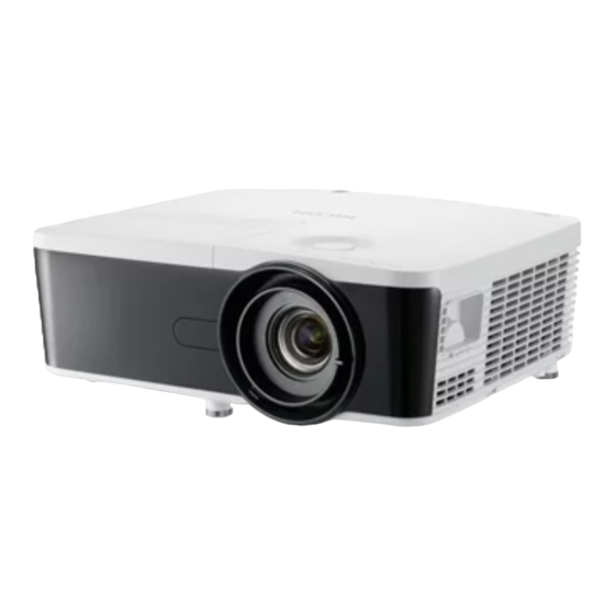
1. Product Information Overview Main Unit 1. LED indicators 2. Remote receiver... -
Page 12: Control Panel
1. Product Information 3. Control panel 4. Ventilation (inlet) 5. Lens shift lever (left/right) 6. Zoom lever 7. Focus ring 8. Adjustable feet 9. Connection ports 10. Lens shift lever (up/down) 11. Lens cap 12. Lens 13. Ventilation (outlet) Control Panel 1. -
Page 13: Led Indicators
Overview LED Indicators 1. Temp indicator 2. Lamp indicator 3. Power indicator Connection Ports 1. LAN terminal 2. Service terminal 3. HDMI 1/MHL In terminal 4. HDMI 2 In terminal 5. DisplayPort terminal 6. Computer 1 In terminal 7. Monitor Out terminal 8. - Page 14 1. Product Information 9. Composite Audio Input (left) terminal 10. Audio 2 In terminal 11. Audio Out terminal 12. 3D Sync terminal 13. Trigger Out (+12v) terminal 14. Microphone jack 15. Audio 3 In terminal 16. Composite Audio Input (right) terminal 17.
-
Page 15: Specifications
Specifications Specifications General Specifications Item Description • 424.0 x 351.8 x 145.0 mm (without feet) Dimensions (W x D x H) • 424.0 x 351.8 x 155.5 mm (with feet) Weight 6.0 ±0.5 kg Power supply Universal AC: 100V - 240V ±10%, 50 - 60Hz •... - Page 16 1. Product Information Item Description • For XGA: 0.7”, DMD 1 chip 2xLVDS (FTP), DDP4421, S600 HB type Number of active dots: 1024x768 DMD chip & Number of active dots • For WUXGA: 0.67”, DMD 1 chip 2xLVDS (FTP), DDP4421, S600 HB type Number of active dots: 1920x1200 •...
-
Page 17: Compatible Mode
Specifications Item Description • D-Sub 15-pin female connector (VGA/Component video) x2 • Mini DIN 4-pin (S-Video) x1 • RCA Jack (Composite Video) x1 • D-SUB 9-pin RS-232 port x1 • RJ45 x1 • D-Sub 15-pin female connector (VGA output) x1 •... - Page 18 1. Product Information Compatibility Resolution Refresh Rate [Hz] 640 x 480 SVGA 800 x 600 1024 x 768 1152 x 864 SXGA 1280 x 1024 Quad VGA 1280 x 960 SXGA+ 1400 x 1050 UXGA 1600 x 1200 WUXGA (RB) 1920 x 1200...
- Page 19 Specifications Compatibility Resolution Refresh Rate [Hz] 640 x 480 66.6 (67) 800 x 600 PowerBook G4 1024 x 768 1152 x 870 1280 x 960 i Mac DV (G3) 1024 x 768 Extended Wide Timing WSVGA 1024 x 600 1280 x 768 WXGA 1280 x 720 1280 x 800...
-
Page 20: Hdmi
1. Product Information Compatibility Resolution Refresh Rate [Hz] 720p 1280 x 720 60 (30) 1080i 1920 x 1080 50 (25) 1080p 1920 x 1080 HDMI Compatibility Resolution Refresh Rate [Hz] PC Signal 640 x 480 SVGA 800 x 600 1024 x 768... - Page 21 Specifications Compatibility Resolution Refresh Rate [Hz] 1152 x 864 SXGA 1280 x 1024 Quad VGA 1280 x 960 SXGA+ 1400 x 1050 UXGA 1600 x 1200 WUXGA (RB) 1920 x 1200 640 x 480 66.6 (67) 800 x 600 PowerBook G4 1024 x 768 1152 x 870 1280 x 960...
- Page 22 1. Product Information Compatibility Resolution Refresh Rate [Hz] 1280 x 768 WXGA 1280 x 720 1280 x 800 1366 x 768 WXGA+ 1440 x 900 WSXGA 1680 x 1050 1920 x 1080-RB WUXGA 1920 x 1080-EIA 1920 x 1200-RB 59.95 Video Signal 480i 720 x 480...
- Page 23 Specifications • If the computer compatibility supportive signal is different from the User’s Manual, refer to the User’s Manual.
- Page 24 1. Product Information...
-
Page 25: Installation
2. Installation Installation Requirements Environment/Power Requirements Operating temperature 5°C to 40°C / 41°F to 104°F Power supply 100 - 240VAC ± 10%, 50 - 60Hz (Auto-ranging and power factor correction) Machine Dimensions • With feet: 424.0 x 351.8 x 155.5 mm (W x D x H) •... -
Page 26: Main Machine Installation
2. Installation Main Machine Installation The user must set this projector up. Accessory Check Description Q’ty Projector Lens Cap... -
Page 27: Precautions
Main Machine Installation Description Q’ty Remote Control (with batteries) Power Cord Carrying Bag CD-ROM (*) RGB Cable Read This First (*) This supplied CD-ROM contains a user’s manual in PDF format. • Due to different applications in each country, some regions may have different accessories. Precautions Please follow all warnings, precautions and maintenance as recommended in this manual to maximize the life of your unit. - Page 28 2. Installation • When the lamp reaches the end of its life, it will burn out and may make a loud popping sound. If this happens, the projector will not turn back on until the lamp module has been replaced. To replace the lamp, follow the procedures listed under “Lamp Cover / Lamp Module”...
- Page 29 Main Machine Installation 4. If a machine is incorrectly installed on a wall or ceiling, it may fall down and cause an injury. Contact your sales or service representative if you want to install a machine on a wall or ceiling.
- Page 30 2. Installation • Do not use attachments not recommended by RICOH. Use of incompatible attachments could cause hazards or damage to the product. • Do not place this product on an unstable cart, stand, tripod, bracket, or table. The product may fall, causing serious injury to a child or adult and serious damage to the product.
-
Page 31: Do Not
Main Machine Installation • The heat from the unit could erase the information on the thermal paper, or cause deformation or warping. • Do not use the product in a closed installation location. Do not place the product in a box or in any other closed installation location. - Page 32 2. Installation...
-
Page 33: Replacement And Adjustment
3. Replacement and Adjustment Special Tools Make sure that engineers are equipped with the following tools, which will be necessary in order to update the firmware, and to perform adjustments that are necessary after replacing the main board (page 49 "Main board assembly"). 1. -
Page 34: Equipment Needed
3. Replacement and Adjustment Equipment Needed 1. Screw bit (+): +No.2 or +No.1 2. Screw bit (+): +No.0 3. Hex sleeves 5 mm 4. Projector... -
Page 35: Parts List
Parts List Parts List Service Parts List • Lens cap • Adjustable foot x3 • Lamp cover • Lamp module • Top cover • LED board • FFC cable (Main board to LED board) • Keypad board • FFC cable (Main board to Keypad board) •... - Page 36 3. Replacement and Adjustment • Lens shift lever (up/down) • Lens shift lever (left/right) • Interlock switch • Color wheel module • Photo sensor board • Thermistor • Harness clamp (for Thermistor) • Harness (Main board to Motor sensor board) •...
-
Page 37: Replaceable Part Hierarchy
Replaceable Part Hierarchy Replaceable Part Hierarchy The flow chart below shows what parts must be removed to access each replaceable part in the projector. The parts on the first level (e.g., Lens cap) are accessible without removing any other parts. The more levels down that a part is, the more parts you need to remove in order to access it. -
Page 38: Part Replacement
3. Replacement and Adjustment Part Replacement • This process is protective level II. Operators should wear electrostatic chains. Lens Cap Untie the string of the lens cap from the bottom cover. Adjustable Foot Remove the 3 adjustable feet [A] from the bottom cover [B]. -
Page 39: Lamp Cover / Lamp Module
Part Replacement Lamp Cover / Lamp Module Loosen the screw and remove the lamp cover [A]. ( ×1) Loosen the screws, and then lift up the lamp handle and remove the lamp module [A]. ( ×2) Top Cover Unit Top cover unit Lamp cover and lamp module (page 37 "Lamp Cover / Lamp Module") - Page 40 3. Replacement and Adjustment Remove the screws from the bottom cover. ( ×5) Remove the filter cover [A] from the right cover. Release the hook at the inside of the top cover.
-
Page 41: Led Board
Part Replacement Disconnect the FFC cables and remove the top cover unit [A]. ( ×2) LED board Top cover unit (page 37 "Top cover unit") Remove the tape [A] on the connector. Remove the FFC cable [A]. ( ×1) -
Page 42: Keypad Board
3. Replacement and Adjustment Remove the LED board [A] from the top cover. ( ×2) • There are two washers attached to the screw at the side of the FFC cable. Keypad board Top cover unit (page 37 "Top cover unit") - Page 43 Part Replacement Remove the tape [A] on the connector. Remove the FFC cable [A]. ( ×1) Remove the keypad board [A] from the top cover. ( ×4)
-
Page 44: Control Panel / Top Cover
3. Replacement and Adjustment Control panel / Top cover Keypad board (page 40 "Keypad board") Separate the control panel [A] and the top cover [B]. Front Cover Top cover unit (page 37 "Top cover unit") Bracket [A] ( ×7) - Page 45 Part Replacement Front cover [A] ( ×3, ×1) • The IR sensor board [A] is attached at the inside of the front cover. Replace the front cover including the IR sensor board.
-
Page 46: Left Cover
3. Replacement and Adjustment Left Cover Front cover (page 42 "Front Cover") Left cover [A] ( ×3) -
Page 47: Blower Fan
Part Replacement Blower Fan Front cover (page 42 "Front Cover") Cut the band [A] and release the fixing wire [B] to separate the blower fan harness [C] and the system fan harnesses [D]. Remove the harness clamp [A] from the bracket and separate it from the blower fan harness [B]. - Page 48 3. Replacement and Adjustment Remove the top blower duct [A]. ( ×2) Blower fan [A] ( ×2, ×1)
-
Page 49: Main Board Assembly
Part Replacement Separate the rubber pad [A] from the bracket. Main Board Assembly • If you need to replace the main board assembly, you have to get into service mode and record the lamp usage hour. (page 84 "Re-write Lamp Hours") Connector list Refer to the table as below for details of each connector. - Page 50 3. Replacement and Adjustment Item Connector on Main Board Key Feature Figure DMD fan Red/Blue/Black wire (3 pin) Speaker Red/Black wire (2 pin) Red/Black/Red/Yellow/White wire, with Motor sensor board black wire tube (5 pin) Red/Black/Yellow wire, with white wire tube IR sensor board (3 pin) Red/Black/White wire, red connector and...
-
Page 51: Main Board Assembly
Part Replacement Item Connector on Main Board Key Feature Figure System fan Red/Blue/Black wire (3 pin) Red/White/Black wire, with black wire tube Blower fan (3 pin) * Be careful not to connect the connectors A, D, E, I and J to the wrong position because they are the same in the pin shape which is 3-pin. -
Page 52: Sub Board
3. Replacement and Adjustment Remove the 4 screws (red circles) and 8 hex screws (yellow circles) from the rear cover. ×12) Main board assembly [A] ( ×6, ×12) Sub board Main board assembly (page 49 "Main board assembly") -
Page 53: Lvps
Part Replacement Sub board [A] ( ×2) • Make sure that the orientation of the connector is correct when attaching the sub board. LVPS Main board assembly (page 49 "Main board assembly") - Page 54 3. Replacement and Adjustment Remove the 2 screws (red circles) and 2 hex screws (yellow circles) from the bracket. ( ×4) Bracket [A] ( ×2) The LVPS is attached to the bottom side of the bracket.
-
Page 55: Psu
Part Replacement Open the black cover, and then remove the LVPS [A] from the holder. ( ×4) Separate the LVPS harness [A] from the LVPS. ( ×1) Remove the bracket including the LVPS. (page 51 "LVPS") -
Page 56: System Fan
3. Replacement and Adjustment PSU [A] ( ×4, ×3) Separate the PSU harness [A] and the LVPS connection harness [B] from the PSU. ( ×2) System Fan Remove the bracket including the LVPS. (page 51 "LVPS") - Page 57 Part Replacement Cut the band [A] and release the fixing wire [B] to separate the blower fan harness [C] and the system fan harnesses [D]. Lift up the system fans [A] to remove them. • Hold the fan module in the correct way.
-
Page 58: Lamp Cable / Lamp Cable Holder
3. Replacement and Adjustment • The two system fans are the same part, so you do not have to worry about connecting the wrong connector. Lamp Cable / Lamp Cable Holder Remove the bracket including the LVPS. (page 51 "LVPS") Lamp cable [A] ( ×1, tape×1) Lamp cable holder [A] (... -
Page 59: Optical System Unit
Part Replacement Optical System Unit Optical system unit Front cover (page 42 "Front Cover") Remove the bracket including the LVPS. (page 51 "LVPS") Optical system unit [A] ( ×4, ×2) -
Page 60: Lens Shift Lever
3. Replacement and Adjustment • When removing the optical system unit, pull out the right cover [A] to pull out the lens shift lever (left/right) [B] from the hole in the cover. Lens shift lever Optical system unit (page 57 "Optical system unit") Lens shift lever (up/down) [A] ( ×2) -
Page 61: Interlock Switch
Part Replacement • The shapes of the two lens shift levers are different: the one for up/down [A] and the one for left/ right [B]. Interlock switch Optical system unit (page 57 "Optical system unit") Interlock switch [A] ( ×2) Color wheel module Interlock switch (page 59 "Interlock... -
Page 62: Photo Sensor Board
3. Replacement and Adjustment Bracket [A] ( ×2) Color wheel module [A] ( ×4) • Do not touch the color wheel [A] when removing the color wheel module. Photo sensor board Color wheel module (page 59 "Color wheel module") -
Page 63: Thermistor
Part Replacement Photo sensor board [A] ( ×1) Thermistor Optical system unit (page 57 "Optical system unit") Thermistor [A] ( ×1) -
Page 64: Motor Sensor Board Harness
3. Replacement and Adjustment Separate the harness clamp [A] from the thermistor. Motor sensor board harness Optical system unit (page 57 "Optical system unit") Motor sensor board harness [A] ( ×1) Right Cover Optical system unit (page 57 "Optical system unit") - Page 65 Part Replacement Release the fixing wire [A] to separate the speaker harness [B] from the DMD fan harness [C]. Right cover [A] ( ×2)
-
Page 66: Speaker (Inside The Right Cover)
3. Replacement and Adjustment Speaker (inside the right cover) Right cover (page 62 "Right Cover") Speaker [A] ( ×2) Rear Cover Left cover (page 44 "Left Cover") Right cover (page 62 "Right Cover") Rear cover [A] ( ×2) -
Page 67: Speaker (Inside The Rear Cover)
Part Replacement Speaker (inside the rear cover) Rear cover (page 64 "Rear Cover") Speaker [A] ( ×2) AC Inlet (page 53 "PSU") Rear cover (page 64 "Rear Cover") - Page 68 3. Replacement and Adjustment AC inlet [A] ( ×3) • Push the bottom cover downward, and then pull out the AC inlet.
-
Page 69: Dmd Fan
Part Replacement DMD Fan Right cover (page 62 "Right Cover") DMD fan [A] and rubber pad [B] ( ×2) Bottom Cover (page 53 "PSU") Blower fan (page 45 "Blower Fan") • Remove the bottom blower duct [A] and plate [B] after removing the blower fan. The plate is inserted into a groove and the front and rear surfaces are different. - Page 70 3. Replacement and Adjustment System fans (page 54 "System Fan") DMD fan (page 67 "DMD Fan") Rear cover (page 64 "Rear Cover") AC inlet (page 65 "AC Inlet") Lamp cable and lamp cable holder (page 56 "Lamp Cable / Lamp Cable Holder") Remove the blower fan bracket [A].
- Page 71 Part Replacement Remove the PSU holder [A]. ( ×3) Adjustable feet (page 36 "Adjustable Foot")
-
Page 72: Required Action After Replacing Parts
3. Replacement and Adjustment Required Action After Replacing Parts After replacing parts, please execute the related items shown in the table below. Changed parts Software Action after Description After Lamp Blower Color repair page Main board LVPS firmware module wheel update Chapter 6. -
Page 73: Troubleshooting
4. Troubleshooting LED Display LED status and meanings Power LED Lamp LED Temp LED Message Blue Standby state Steady light (Input power cord) Power on Flashing (Warming up) Power on & lamp Steady light lighting Power off Flashing (Cooling down) Programming Steady light Steady light... -
Page 74: Main Procedures
4. Troubleshooting Main Procedures Symptom Procedure • Ensure the power cord and AC power outlet are securely connected • Ensure all connectors are securely connected and aren’t No power broken • Check LVPS • Check Main board • Ensure the projector is not put on a soft pad and the air vent is not blocked a. - Page 75 Main Procedures Symptom Procedure • Ensure the signal cables and source work (If you connect multiple sources at the same time, use the "Source" button switch) • Ensure all connectors are securely connected and aren’t No image broken • Check Main board •...
- Page 76 4. Troubleshooting Symptom Procedure • Ensure that the signal cables and source work as well Garbage image • Check Main board • Remote controller a. Check Battery Remote controller b. Check Remote controller failed c. Check IR sensor board d. Check Main board •...
-
Page 77: Rod Adjustment
Rod Adjustment Rod Adjustment If either of the defects ringed in red appears when projecting an image, perform the adjustment described below. Environment • The size of screen is 60. • This process should be done in a dark environment (under 2 lux). Procedure 1. - Page 78 4. Troubleshooting...
-
Page 79: Test & Inspection
5. Test & Inspection Service Mode How to Enter the Service Mode Turn on the projector. Press the "Power [1]", "Left [2]", "Left [2]" and "Menu [3]" keys sequentially. • You can use the remote controller to enter the service mode in the same way. •... - Page 80 5. Test & Inspection Setting Item Description Read only MCU ver. Shows the present MCU firmware version of the projector. Waveform ID Read only System Hours (total) Read only Lamp Hours (DD+ED) Read only Lamp Hours (full) Read only Lamp Hours (eco) Read only Factory Reset Burn In Test...
- Page 81 Service Mode Setting Item Description PC Green Offset PC Blue Offset Red Gain Green Gain Blue Gain Video Red Offset Video Blue Offset Reset Calibration Data Optical Settings Setting Item Description Waveform ID Read only Use this to adjust the R/G/B value to improve the Color Wheel Index image when the color reproduction is not correct.
- Page 82 5. Test & Inspection Setting Item Description Use this to change the working hours of the Lamp Hours (DD+ED) projector in DD + ED. (page 84 "Re-write Lamp Hours") Use this to change the working hours of the Lamp Hours (full) projector in full mode.
- Page 83 Service Mode Setting Item Description Current Lamp Voltage Read only Fan Zeta Value (1/100) High Altitude Lamp Power Mode EQ Settings Setting Item Description Set EQ Value Get EQ Value Read only EQ_Red Read only EQ_Green Read only EQ_Blue Read only...
-
Page 84: Test Equipment And Conditions
5. Test & Inspection Test Equipment and Conditions Test Equipment Needed • PC support HDTV resolution & Independent graphic card • Blue- ray DVD player support “S-Video”, “3D source files”, ”HDMI” and “Video” • Illuminance meter • Video generator Recommended Test Condition •... -
Page 85: Calibration
Calibration Calibration Waveform Download and Fan Calibration After replacing LVPS, the main board, the blower fan, or updating the firmware, do the following steps. While pressing the "Power" key, plug in the power cord. When the "Power LED" flashes blue, release the "Power" key. When the "Power LED"... -
Page 86: Re-Write Lamp Hours
5. Test & Inspection Re-write Lamp Hours After replacing the main board, you must rewrite the lamp hours. Write down the lamp hours before the replacement and put back the same value after replacing the board. Get into service mode. (page 77 "How to Enter the Service Mode") Select "Other Settings", and then press the "Enter"... - Page 87 Re-write Lamp Hours Select “System Hours (total)”, then use the “Left” or “Right” keys to re-write the System Hours. Select “Lamp Hours (DD+ED)”, then use the “Left” or “Right” keys to re-write the Lamp Hours.
- Page 88 5. Test & Inspection Select “Lamp Hours (full)”, then use the “Left” or “Right” keys to re-write the Lamp Hours. Select “Lamp Hours (eco)”, then use the “Left” or “Right” keys to re-write the Lamp Hours. • “Left” key = decrease lamp hours •...
-
Page 89: Color Wheel Index
Color Wheel Index Color Wheel Index After replacing the main board or color wheel, "Color Wheel Index" should be done. Get into service mode. (page 77 "How to Enter the Service Mode") Select "Color Wheel Index", and then use the "Left" or "Right" keys to adjust the color balance of the projected image. - Page 90 5. Test & Inspection • By pressing the "Enter" key, the test pattern can be projected. • This adjustment procedure can be executed as well in the following steps: Optical Settings > Color wheel Index...
-
Page 91: Test Inspection Procedure
Test Inspection Procedure Test Inspection Procedure Check points Check item Check point Firmware version All firmware version must be the latest version TB implementation Related TB must be implemented Exterior The exterior must be undamaged. Missing logo, missing prints and blurred prints are Logo unacceptable Lamp cover... - Page 92 5. Test & Inspection...
-
Page 93: Update
6. Update Firmware Update Equipment Needed Software • DLP Composer Lite • Firmware (*.img) • HD26FlashDeviceParameters • Download "DLP Composer Lite" and "HD26FlashDeviceParameters" from website to update FW procedure. Hardware 1. Projector 2. Power cord 3. USB Cable mini USB to USB (A) 4. -
Page 94: Firmware Update Procedure
6. Update Firmware Update Procedure DLP composer lite setup procedure Execute “DLP Composer Lite v** Setup” Program. Click “Next”. Read “License Agreement”, and then choose “I accept and agree to be bound by all the terms and conditions of this License Agreement” and click “Next”. - Page 95 Firmware Update Click “Next”. Click “Next”. Click “Next”.
-
Page 96: Get Into Firmware Download Mode
6. Update The program is executing “installing” status. Click “Finish”. Get into firmware download mode Set up the following procedure. While holding down the “Power” key, plug in the power cord. -
Page 97: Usb Driver Update Procedure
Firmware Update After the Power LED lights pink, and the Lamp and Temp LEDs light red, then release the “Power” key as shown in the photo below. USB driver update procedure Execute “Install DLP Device Drivers” in the start menu. - Page 98 6. Update Select “Jungo WinDriver (WinVista/Win7)”, then click “install”. • If OS is 64bit, select “Microsoft WinUSB”. Click “Next”.
-
Page 99: Connect The Projector To The Pc
Firmware Update Click “Finish”. Connect the projector to the PC Get into firmware download mode. (page 94 "Get into firmware download mode") Connect the Projector and PC with a mini USB cable. The Found New Hardware Wizard appears. Select "No, not this time", then click "Next". -
Page 100: Firmware Update Procedure
6. Update Select "Install the software automatically (Recommended)”, then click "Next". Click "Finish". Firmware update procedure Execute the “DLP Composer Lite **” file. Select the file “V1FlashDeviceParameters”. - Page 101 Firmware Update Put “V1FlashDeviceParameters” file into the folder where you setup “DLP Composer Lite **”. Click “Edit” and “Preferences”.
- Page 102 6. Update Click “Communications” and select “USB” then click “OK”. Choose “Flash Loader” and click “Browse” to search the firmware file (*.img) and click “Open”.
- Page 103 Firmware Update Select the item “Skip Boot Loader Area” and select “64KB” then click “Reset Bus” to erase the flash memory. If the firmware is ready, click “Start Download” to execute the firmware update. Click “Yes” to erase the flash memory. . It takes about several minutes, the firmware update process is finished, “Download completed”...
-
Page 104: Check System Firmware Version
6. Update Unplug the USB cable and power cord. Check system firmware version Re-plug in the power cord, and then restart the projector. Get into the Service Mode. (page 77 "How to Enter the Service Mode") Check the system firmware version. -
Page 105: Network Firmware Update
Network Firmware Update Network Firmware Update Equipment Needed Software • ***_Network firmware_***.bin (*.bin) • For updating Network firmware, use IE7.0 or a later version. Hardware 1. Projector 2. Power cord 3. LAN Cable 4. PC / Laptop... -
Page 106: Network Firmware Update Procedure
6. Update Network Firmware Update Procedure Confirm the projector IP Plug the power cord and LAN cable into the projector. Turn on the projector, then press the "Menu" key to get into the OSD menu. Use the down key to select "Setting". Select "Network", and then press the "Enter"... -
Page 107: Pc Network Setting
Network Firmware Update Make sure that “DHCP” is “Off”. Write down the IP address and subnet mask: 192.168.0.100 and 255.255.255.0, in this example. PC network setting Double click “Local area connection”, then choose “Properties”. -
Page 108: Network Firmware Update Procedure
6. Update Select “Internet protocol (TCP/IP)”, and then click “Properties”. Modify the IP address to 192.168.0.101, and modify the subnet mask to 255.255.255.0. The subnet mask of the PC must be the same as the projector. The HOST ID or IP address (192.168.0.XXX) of the PC must be different from the projector IP address written down earlier. - Page 109 Network Firmware Update Click "Update". Click "Browse". Select the network firmware file (*.bin) which you saved, and then click “Open”.
- Page 110 6. Update Click “Update” to start updating. The following appears when the firmware update procedure is complete. Click "Re Login". Enter "admin" for password. The projector network firmware version will appear.
- Page 111 Network Firmware Update...
- Page 112 MEMO...
- Page 113 MEMO...
- Page 114 MEMO...
Need help?
Do you have a question about the Hadar-PJ1 and is the answer not in the manual?
Questions and answers