
Related Manuals for Ricoh Polaris-PJ1


Summary of Contents for Ricoh Polaris-PJ1
- Page 1 Polaris-PJ1 Machine Codes: Y042/Y043/Y044/Y048/Y049 /Y062/Y063/Y064/Y065/Y066 Field Service Manual 1 July, 2014...
-
Page 3: Important Safety Notices
Important Safety Notices Important Safety Notices Prevention of physical injury 1. Before disassembling or assembling parts of the main machine and peripherals, make sure that the power cord of the main machine is unplugged. 2. The wall outlet should be near the machine and easily accessible. 3. -
Page 4: Table Of Contents
TABLE OF CONTENTS Important Safety Notices........................... 1 Important Safety Notices..........................1 Prevention of physical injury......................... 1 Health safety conditions........................1 Observance of electrical safety standards..................1 Safety and Ecological Notes for Disposal....................1 1. Product Information Overview................................5 Main Unit................................ 5 Control Panel.............................. - Page 5 Keypad board / IR sensor board......................27 Zoom ring............................28 Control panel / Top cover......................... 29 Speaker................................ 30 Lamp Housing.............................. 31 Lamp housing............................31 System fan / Interlock switch......................32 LVPS................................33 Optical System Unit............................. 35 Connector list............................36 Optical system unit..........................37 IO cover / IO seal..........................38 Photo sensor board..........................
- Page 6 ADC Calibration............................60 PC calibration............................60 Re-write Lamp Hours............................62 Color Wheel Index............................65 Test Inspection Procedure..........................66 Check points..............................66 OSD Reset..............................66 6. Update Firmware Update............................. 67 Equipment Needed............................67 Firmware Update Procedure........................68 DLP composer lite setup procedure ....................68 Get into firmware download mode....................70 USB driver update procedure ......................
-
Page 7: Product Information
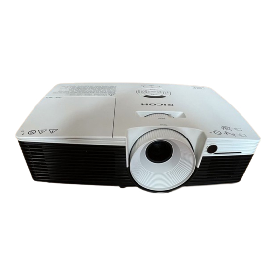
1. Product Information Overview Main Unit 1. Zoom lever 2. Control panel 3. Connection ports... -
Page 8: Control Panel
1. Product Information 4. Ventilation (inlet) 5. Security chain opening 6. Speaker 7. Remote Receiver 8. Adjustable feet 9. Anti-theft lock hole (Kensington lock) 10. Lens cap 11. Lens 12. Ventilation (outlet) 13. Focus ring Control Panel 1. Keystone 2. Auto set 3. -
Page 9: Connection Ports
Overview 5. Temp indicator 6. Power indicator 7. Lamp indicator 8. Power 9. Menu 10. Input 11. Enter Connection Ports 1. S-Video In terminal 2. Monitor Out terminal 3. Computer 1 In terminal 4. Computer 2 In terminal 5. AC In socket 6. - Page 10 1. Product Information • The interface is subject to model’s specifications.
-
Page 11: Specifications
Specifications Specifications General Specifications Item Description • 314.3 x 223.6 x 88.2 mm (without feet) Dimension (W x D x H) • 314.3 x 223.6 x 101.7 mm (with feet) Weight 2.5±0.5Kg Power supply Universal AC: 100V - 240V ± 10%, 50 - 60Hz •... -
Page 12: Compatible Mode
1. Product Information Item Description Aspect ratio • 4:3, 16:9, Native, Auto • VGA-in x2 • Composite Video x1 • S-Video x1 Input signal spec • Audio In(stereo), 3.5mm x1 • RS232 x1 • USB, Type B x1 • HDMI V1.4 x 1 •... - Page 13 Specifications Signal Resolution V. Frequency [KHz] H. Frequency [KHz] 800 x 600 35.1 800 x 600 37.9 800 x 600 48.1 SVGA 800 x 600 46.9 800 x 600 53.7 800 x 600 77.4 1024 x 768 48.4 1024 x 768 56.5 1024 x 768 60.0...
- Page 14 1. Product Information Signal Resolution V. Frequency [KHz] H. Frequency [KHz] 640 x 480 31.4 640 x 480 66.6(67) 34.9 800 x 600 37.9 PowerBook G4 1024 x 768 48.4 1152 x 870 68.7 1280 x 960 75.0 iMac DV (G3) 1024 x 768 60.0 1280 x 768...
-
Page 15: Installation
2. Installation Installation Requirements Environment/Power Requirements Operating temperature 5ºC to 40ºC / 41°F to 104°F Power supply 100 - 240VAC ± 10%, 50 - 60Hz (Auto-ranging and power factor correction) Machine Dimensions • With feet: 314.3 x 223.6 x 101.7 mm (W x D x H) •... -
Page 16: Main Machine Installation
2. Installation Main Machine Installation The user must set this projector up. Accessory Check Description Q’ty Projector Lens Cap Remote Control Power Cord Carrying Bag... -
Page 17: Precautions
Main Machine Installation Description Q’ty CD (*) RGB Cable Read This First (*) This supplied CD-ROM contains a user’s manual in PDF format. • Due to different applications in each country, some regions may have different accessories. Precautions Please follow all warnings, precautions and maintenance as recommended in this manual to maximize the life of your unit. - Page 18 2. Installation • Do not remove the cabinet cover, or you may be exposed to dangerous voltage. Refer servicing to qualified service personnel only. • This product should be operated only from the type of power source which does not exceed the voltage range specified on the rating label and the power cord.
- Page 19 The top and bottom surface of this product increase in temperature during normal use and may damage the other unit. • Do not use attachments not recommended by RICOH. Use of incompatible attachments could cause hazards or damage to the product.
- Page 20 2. Installation • Do not place this product on an unstable cart, stand, tripod, bracket, or table. The product may fall, causing serious injury to a child or adult and serious damage to the product. • Unplug this product from the wall outlet and take the product to qualified service personnel if you encounter any of the following conditions: 1.
-
Page 21: Do Not
Main Machine Installation • Do not use the product in a closed installation location. Do not place the product in a box or in any other closed installation location. Otherwise it may overheat, which could result in a risk of fire. •... - Page 22 2. Installation...
-
Page 23: Replacement And Adjustment
3. Replacement and Adjustment Special Tools Make sure that engineers are equipped with the following tools, which will be necessary in order to update the firmware, and to perform adjustments that are necessary after replacing the optical engine / main board assembly (page 42 "Optical engine / Main board assembly"). 1. -
Page 24: Equipment Needed
3. Replacement and Adjustment Equipment Needed 1. Screw bit (+): +No.2 or +No.1 2. Screw bit (+): +No.0 3. Jeweler's Screwdriver (+) 4. Hex sleeves 5 mm 5. Long nose nipper 6. Tweezers 7. Projector... -
Page 25: Parts List
Parts List Parts List Service Parts List • Lens cap • Lamp cover • Lamp module • Keypad board • IR sensor board • FFC cable • Zoom ring • Control panel • Control panel (Enter key) • Top cover •... -
Page 26: Replaceable Part Hierarchy
3. Replacement and Adjustment Replaceable Part Hierarchy The flow chart below shows what parts must be removed to access each replaceable part in the projector. The parts on the first level (e.g., Lens cap) are accessible without removing any other parts. The more levels down that a part is, the more parts you need to remove in order to access it. -
Page 27: Part Replacement
Part Replacement Part Replacement • This process is protective level II. Operators should wear electrostatic chains. Lamp Cover / Lamp Module Loosen the 1 screw, and then remove the lamp cover [A]. -
Page 28: Top Cover Unit
3. Replacement and Adjustment Loosen the 1 screw and unplug the 1 connector, then take off the lamp module [A]. Top Cover Unit Top cover unit Remove the 6 screws from the bottom cover. -
Page 29: Keypad Board / Ir Sensor Board
Part Replacement Unplug FFC cable and remove the top cover [A]. • Align the dent part of the zoom ring with the tab part on the optical engine side when attaching the top cover. Keypad board / IR sensor board Top cover unit (page 26 "Top cover unit") -
Page 30: Zoom Ring
3. Replacement and Adjustment Remove the 4 screws and 3 connectors and separate the keypad board [B] and IR sensor board [C] and FFC cable [D] from the top cover [A]. • When removing the IR sensor board, unfasten the 3 tenons. Zoom ring Top cover unit (page 26 "Top cover... -
Page 31: Control Panel / Top Cover
Part Replacement Remove the 1 screw, and then remove the zoom ring [A] from the top cover [B]. Separate the bracket [A] and zoom ring [B]. Control panel / Top cover Keypad board / IR sensor board (page 27 "Keypad board / IR sensor board") -
Page 32: Speaker
3. Replacement and Adjustment Separate the control panel [A] and the top cover [B]. Speaker Top cover unit (page 26 "Top cover unit") Unplug the 1 connector to remove the speaker [A]. -
Page 33: Lamp Housing
Part Replacement Separate the rubber [A] and speaker [B]. Lamp Housing Lamp housing Lamp Cover / Lamp Module (page 25 "Lamp Cover / Lamp Module") Top cover unit (page 26 "Top cover unit") Remove the 3 screws and the 3 connectors, and then take out the lamp housing [A]. •... -
Page 34: System Fan / Interlock Switch
3. Replacement and Adjustment System fan / Interlock switch Lamp housing (page 31 "Lamp housing") Remove the 1 screw to separate the lamp cable [A]. Remove the 4 screws to separate the system fan [A]. -
Page 35: Lvps
Part Replacement • Take the fan module as the right gesture. Remove the 1 screw to separate the interlock switch [A]. LVPS Lamp housing (page 31 "Lamp housing") - Page 36 3. Replacement and Adjustment Remove the 5 screws and 3 connectors to remove the LVPS and holder [A]. Remove the 2 screws. Remove the 5 screws and 2 connectors to separate the LVPS [A].
-
Page 37: Optical System Unit
Part Replacement Optical System Unit • If you need to replace the optical engine / main board assembly, you have to get into service mode and record the lamp usage hour. (page 62 "Re-write Lamp Hours") -
Page 38: Connector List
3. Replacement and Adjustment Connector list Refer to the table as below for details of each connector. Male Connector on Item Key Feature Figure Main Board Speaker Red/Black wire (2 pin) Red/Black/White wire, red Photo sensor connector (3 pin) System fan Red/Blue/Black wire (3 pin) LVPS A Red wire tube (10 pin) -
Page 39: Optical System Unit
Part Replacement Male Connector on Item Key Feature Figure Main Board LVPS B Black wire tube (5 pin) Red/White/Black wire, with blue Blower fan wire tube (3 pin) Optical system unit Speaker (page 30 "Speaker") LVPS (page 33 "LVPS") Remove the 4 screws. Remove the 4 screws and 1 connector to remove the optical system unit [A]. -
Page 40: Io Cover / Io Seal
3. Replacement and Adjustment IO cover / IO seal Optical system unit (page 37 "Optical system unit") Remove the 8 hex screws to remove IO cover (with IO seal) [A]. Photo sensor board Optical system unit (page 37 "Optical system unit") -
Page 41: Focus Ring
Part Replacement Remove the 1 screw and 1 connector to remove the photo sensor board [A]. Focus ring Optical system unit (page 37 "Optical system unit") Remove the 1 screw and unfasten the 2 tenons, then push out the focus ring [A]. Thermistor Optical system unit (page 37 "Optical system... -
Page 42: Color Wheel
3. Replacement and Adjustment Remove the 1 screw to remove the thermistor [A]. Color wheel Photo sensor board (page 38 "Photo sensor board") Thermistor (page 39 "Thermistor") Remove the 2 screws to remove the color wheel module and color wheel holder [A]. - Page 43 Part Replacement Remove the 2 screws to remove the color wheel [A]. • Make sure that the color wheel [A] does not touch the color wheel holder when removing the color wheel [A]. • It is recommended to slide and remove the color wheel as shown by arrows in the following figure.
-
Page 44: Optical Engine / Main Board Assembly
3. Replacement and Adjustment Optical engine / Main board assembly IO cover / IO seal (page 38 "IO cover / IO seal") Focus ring (page 39 "Focus ring") Color wheel (page 40 "Color wheel") Remove the 2 screws to remove the heat sink [A] from the optical engine / main board assembly [B]. -
Page 45: Base / Adjustable Foot
Part Replacement Remove 2 points (as shown by red circles in the following figure) from the blower holder to remove the blower fan [A]. Base / Adjustable Foot Blower Fan (page 42 "Blower Fan") Remove the 2 screws to remove the blower holder [A]. - Page 46 3. Replacement and Adjustment Remove the 3 adjustable feet [A] from the base unit [B]. • The front adjustable foot is different in size from the rear adjustable feet.
-
Page 47: Required Action After Replacing Parts
Required Action After Replacing Parts Required Action After Replacing Parts After replacing parts, please execute the related items shown in the table below. Changed parts Software Main board Action after After (Optical Description page Lamp Blower Color repair firmware engine / Main module wheel update... - Page 48 3. Replacement and Adjustment • If color appears abnormal after changing the main board, do the color wheel index adjustment. (page 65 "Color Wheel Index")
-
Page 49: Troubleshooting
4. Troubleshooting LED Display LED status and meanings Power LED Lamp LED Temp LED Message Blue Standby state Steady light (Input power cord) Flashing Power on 0.5 sec off (Warming up) 0.5 sec light Power on Steady light & lamp lighting Flashing Power off 0.5 sec off... - Page 50 4. Troubleshooting Power LED Lamp LED Temp LED Message Blue Lamp error Steady light Steady light (Lamp failed on standby) Fan error Steady light Flashing (Fan failed on event) Fan error Steady light Flashing (Fan failed on standby) Error (Color wheel fail / Striking lamp fail on Steady light Flashing...
-
Page 51: Main Procedures
Main Procedures Main Procedures Symptom Procedure • Ensure the power cord and AC power outlet are securely connected • Ensure all connectors are securely connected and aren’t No power broken • Check LVPS • Check Main board • Ensure the projector is not put on a soft pad and the air vent is not blocked a. - Page 52 4. Troubleshooting Symptom Procedure • Ensure the signal cable and source work (If you connect multiple sources at the same time, use the "Source" button switch) • Ensure all connectors are securely connected and aren’t broken No image • Check Main board •...
- Page 53 Main Procedures Symptom Procedure • Ensure the projection screen without dirt • Ensure the projection lens is clean Dead pixel/Dust • Clean DMD chip and Optical engine (Out of spec.) • Check DMD chip • Check Optical engine • Ensure that the signal cables and source work as well Garbage image •...
-
Page 54: Rod Adjustment
4. Troubleshooting Rod Adjustment If either of the defects ringed in red appears when projecting an image, perform the adjustment described below. Environment • The size of screen is 60. • This process should be done in a dark environment (under 2 lux). Procedure 1. -
Page 55: Test & Inspection
5. Test & Inspection Service Mode How to Enter the Service Mode Turn on the projector. Press the "Power [1]", "Left [2]", "Left [2]" and "Menu [3]" keys sequentially. • You can use the remote controller to enter the service mode in the same way. •... - Page 56 5. Test & Inspection Service Menu Setting Item Description Read only Model Name Shows the name of the projector. Read only DDP ver. Shows the present DDP version of the projector. Read only MCU ver. Shows the present MCU firmware version of the projector. Waveform ID Read only System Hours (total)
- Page 57 Service Mode Analog Settings Setting Item Description Use this to adjust the R/G/B value to improve the PC Calibration image when the color reproduction is not correct. (page 60 "ADC Calibration") Video Calibration PC Red Offset PC Green Offset PC Blue Offset Red Gain Green Gain Blue Gain...
- Page 58 5. Test & Inspection Setting Item Description Lamp Power Mode Other Settings Setting Item Description Use this to change operating hours of the System Hours (total) projector. (page 62 "Re-write Lamp Hours") Use this to change the working hours of the Lamp Hours (DD+ED) projector in DD + ED.
- Page 59 Service Mode Setting Item Description Factory Blower RPM Read only Lamp Blower Fan Volt (1/10) Read only Lamp Blower Fan RPM Read only Temperature Degree Read only Current Lamp Voltage Read only Fan Zeta Value (1/100) High Altitude Lamp Power Mode...
-
Page 60: Test Equipment And Conditions
5. Test & Inspection Test Equipment and Conditions Test Equipment Needed • PC support HDTV resolution & Independent graphic card • Blue- ray DVD player support “S-Video”, “3D source files”, ”HDMI” and “Video” • Illuminance meter • Video generator Recommended Test Condition •... -
Page 61: Calibration
Calibration Calibration Fan Calibration After replacing the optical engine / main board assembly, the blower fan, or updating the firmware, do the following steps. While pressing the "Power" key, plug in the power cord. When the "Power LED" flashes red, release the "Power" key. After 3 to 5 seconds, the projector will power on. -
Page 62: Adc Calibration
5. Test & Inspection ADC Calibration PC calibration • After replacing the optical engine / main board assembly, do the following steps. • If you do not have professional equipment such as Quantum Data 802B or CHROMA2327, use a PC that supports HDTV resolution & has an independent graphics card to output the corresponding PC pattern. - Page 63 Calibration Select "Analog Settings". Execute “PC Calibration”. Select "Return to Service Menu" to confirm the setting.
-
Page 64: Re-Write Lamp Hours
5. Test & Inspection Re-write Lamp Hours After replacing the optical engine/main board assembly, you must rewrite the lamp hours. Write down the lamp hours before the replacement and put back the same value after replacing the board. Get into service mode. (page 53 "How to Enter the Service Mode") Select "Other Settings", and then press the "Enter"... - Page 65 Re-write Lamp Hours Select “System Hours (total)”, then use the “Left” or “Right” keys to re-write the System Hours. Select “Lamp Hours (DD+ED)”, then use the “Left” or “Right” keys to re-write the Lamp Hours.
- Page 66 5. Test & Inspection Select “Lamp Hours (full)”, then use the “Left” or “Right” keys to re-write the Lamp Hours. Select “Lamp Hours (eco)”, then use the “Left” or “Right” keys to re-write the Lamp Hours. • “Left” key = decrease lamp hours •...
-
Page 67: Color Wheel Index
Color Wheel Index Color Wheel Index After replacing the optical engine/main board assembly or color wheel, "Color Wheel Index" should be done. Get into service mode. (page 53 "How to Enter the Service Mode") Select "Color Wheel Index", and then use the "Left" or "Right" keys to adjust the color balance of the projected image. -
Page 68: Test Inspection Procedure
5. Test & Inspection Test Inspection Procedure Check points Check item Check point Firmware version All firmware version must be the latest version TB implementation Related TB must be implemented Exterior The exterior must be undamaged. Missing logo, missing prints and blurred prints are Logo unacceptable Lamp cover... -
Page 69: Update
6. Update Firmware Update Equipment Needed Software • DLP Composer Lite 11.2 • Firmware (*.img) • 11.2 FlashDeviceParameters • Download "DLP Composer Lite 11.2" and "11.2 FlashDeviceParameters" from website to update FW procedure. Hardware 1. Projector 2. Power cord 3. USB Cable mini USB to USB (A) 4. -
Page 70: Firmware Update Procedure
6. Update Firmware Update Procedure DLP composer lite setup procedure Execute “DLP Composer Lite v** Setup” Program. Click “Next”. Read “License Agreement”, and then choose “I accept and agree to be bound by all the terms and conditions of this License Agreement” and click “Next”. - Page 71 Firmware Update Click “Next”. Click “Next”. Click “Next”.
-
Page 72: Get Into Firmware Download Mode
6. Update The program is executing “installing” status. Click “Finish”. Get into firmware download mode Set up the following procedure. Hold on “Power” button and plug in the power cord. -
Page 73: Usb Driver Update Procedure
Firmware Update After the power LED lights pink, lamp and temp LED light red, then release “Power” button as shown in the photo below. USB driver update procedure Execute “Install DLP Device Drivers” in start menu. - Page 74 6. Update Select “Jungo WinDriver (WinVista/Win7), then click “install”. • If OS is 64bit, select “Microsoft WinUSB”. Click “Next”.
-
Page 75: Connect The Projector To The Pc
Firmware Update Click “Finish”. Connect the projector to the PC Get into firmware download mode.(page 70 "Get into firmware download mode") Connect the Projector and PC with a mini USB cable. The Found New Hardware Wizard appears. Select "No, not this time", then click "Next". -
Page 76: Firmware Update Procedure
6. Update Select "Install the software automatically (Recommended)”, then click "Next". Click "Finish". Firmware update procedure Execute the “DLP Composer Lite **” file. Select the file “FlashDeviceParameters”. - Page 77 Firmware Update Put “FlashDeviceParameters” file into the folder where you setup “DLP Composer Lite **”. Click “Edit” and “Preferences”.
- Page 78 6. Update Click “Communications” and select “USB” then click “OK”. Choose “Flash Loader” and click “Browse” to search the firmware file (*.img) and click “Open”.
- Page 79 Firmware Update Select the item “Skip Boot Loader Area” and select “32KB” then click “Reset Bus” to erase the flash memory. If the firmware is ready, click “Start Download” to execute the firmware update. Click “Yes” to erase the flash memory. . It takes about several minutes, the firmware update process is finished, “Download completed”...
-
Page 80: Check System Firmware Version
6. Update Unplug USB cable and power cord. Check system firmware version Re-plug in power cord, and then restart the projector. Get into the Service Mode. (page 53 "How to Enter the Service Mode") Check the system firmware version. - Page 81 MEMO...
- Page 82 MEMO...
Need help?
Do you have a question about the Polaris-PJ1 and is the answer not in the manual?
Questions and answers