
Related Manuals for Ricoh Antares-PJ1 Series


Summary of Contents for Ricoh Antares-PJ1 Series
- Page 1 Model Antares-PJ1 Machine Codes: Y020/Y021/Y022 Field Service Manual 26 August, 2011...
-
Page 3: Regulation & Safety Notices
Regulation & Safety Notices Safety Labels of This Machine 1. Do not block the air intake or exhaust. Doing so could cause a fire due to internal overheating. Do not place your hands, face, or other objects near the air exhaust, the lamp cover or the bottom of the unit. - Page 4 • Connect the device into an outlet on a circuit different from that to which the receiver is connected. • Consult the dealer or an experienced radio/television technician for help. RESPONSIBLE PARTY: Ricoh Americas Corporation 5 Dedrick Place, West Caldwell, NJ 07006...
-
Page 5: Notice: Canadian Users
Notice: Shielded cables All connections to other computing devices must be made using shielded cables to maintain compliance with FCC regulations. Caution Changes or modifications not expressly approved by the manufacturer could void the user's authority, which is granted by the Federal Communications Commission, to operate this projector. USA Only LAMP(S) INSIDE THIS PRODUCT CONTAIN MERCURY AND MUST BE RECYCLED OR DISPOSED OF ACCORDING TO LOCAL, STATE OR FEDERAL LAWS. -
Page 6: Remote Control Batteries
The following information is only for EU-member states: The use of the symbol indicates that this product may not be treated as household waste. By ensuring this product is disposed of correctly, you will help prevent potential negative consequences for the environment and human health, which could otherwise be caused by inappropriate waste handling of this product. -
Page 7: Other Information
The crossed out wheeled dust bin symbol indicates that batteries and/or accumulators must be collected and disposed of separately from household waste. If the battery or accumulator contains more than the specified values of lead (Pb), mercury (Hg), and/or cadmium (Cd) defined in the Battery Directive (2006/66/EC), then the chemical symbols for lead (Pb), mercury (Hg) and/or cadmium (Cd) will appear below the crossed out wheeled dust bin symbol. -
Page 8: Table Of Contents
TABLE OF CONTENTS Regulation & Safety Notices..........................1 Safety Labels of This Machine........................1 Notice: Users in the United States of America.....................1 Notice: Canadian users..........................3 Notice: Users in Turkey..........................3 Declaration of Conformity for EU countries....................3 Disposal................................3 Remote Control Batteries..........................4 Other Information............................5 1. Product Information Specifications..............................9 Overview................................10 Names of the Terminals on the Rear Panel....................11... - Page 9 Blower................................31 LVPS................................32 Interlock Switch............................35 Lamp Driver..............................35 Bottom Shielding............................37 Speaker................................38 Bottom Cover...............................38 Electrical Adjustment............................39 Adjustment Points vs Part Replaced......................39 Verifying the Operation after Parts Replacement..................39 4. System Maintenance Service Mode..............................45 How to enter the Service Mode........................45 Service Mode Settings..........................45 Functional Tests..............................49 Equipment Needed............................49 Video Performance............................49 Others................................51...
-
Page 11: Product Information
1. Product Information Specifications See "Appendices" for the following information: • General Specifications... -
Page 12: Overview
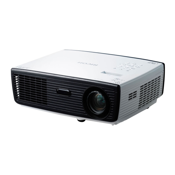
1. Product Information Overview 1. Control panel 2. Zoom ring 3. Ventilation (inlet) 4. Speaker 5. Focus ring 6. Ventilation (outlet) 7. Infrared remote sensor 8. Lens 9. Lens cap 10. Connection ports 11. Adjustable feet... -
Page 13: Names Of The Terminals On The Rear Panel
Overview Names of the Terminals on the Rear Panel 1. HDMI terminal Input for digital signals from a HDMI (High-Definition Multimedia Interface) compatible digital source. 2. COMPUTER IN/COMPONENT IN terminal Input for analog RGB signals from a computer or a component video signal (Y/PB/PR) from video equipment. 3. - Page 14 1. Product Information...
-
Page 15: Installation
2. Installation Precautions Follow all warnings, precautions and maintenance as recommended in this user's guide to maximize the life of your unit. • This apparatus must be earthed. • Do not look into the projector's lens when the lamp is on. The bright light may hurt your eyes. •... - Page 16 2. Installation • Do not place or keep the projector within the reach of the children. It may fall or tip over, possibly causing serious injury. • Do not stack other equipment on this product and do not place this product on other equipment. The top and bottom surface of this product increase in temperature during normal use and may damage the other unit.
-
Page 17: Do Not
Precautions • After unpacking this product, read the manual carefully, and follow all the operating and other instructions. • Turn off the product before cleaning. • Use a soft cloth moistened with mild detergent to clean the display housing. • Disconnect the power plug from AC outlet if the product is not being used for a long period of time. Do not •... - Page 18 2. Installation...
-
Page 19: Replacement And Adjustment
3. Replacement and Adjustment Equipment Needed & Product Overview • Screw driver (+): 105 • Screw driver (+): 107 • Screw driver (-): 107 • Hex Sleeves 5 mm • Tweezers • Projector • Before you start: This process requires protection level II. Operators should wear antistatic clothing. •... -
Page 20: Part Replacement
3. Replacement and Adjustment Part Replacement Lamp Cover Loosen 2 screws (red circles) on the Lamp Cover. Remove the Lamp Cover and tear off the aluminum foil. Lamp Module... -
Page 21: Top Cover
Part Replacement Loosen 2 screws (red circles) on the Lamp Module. Take off the Lamp Module. Top Cover Unscrew 2 screws (red circles) from the Bottom Cover. -
Page 22: Keypad Board
3. Replacement and Adjustment Unscrew 2 screws (green circles) from the IO Cover. Pressing the Top Cover's sides as shown, unhook the catches and remove the Top Cover. Unplug the connector (purple square) of the Keypad Board. Keypad Board... -
Page 23: Zoom Ring Module
Part Replacement Unscrew 4 screws (red circles) from the Top Cover. Remove the Keypad Board. Zoom Ring Module Unscrew 3 screws (red circles) from the Top Cover. Remove the Zoom Ring Module. -
Page 24: Top Shielding
3. Replacement and Adjustment Top Shielding Unscrew 9 screws (red circles). Remove the Top Shielding. IO Cover... -
Page 25: Main Board
Part Replacement Unscrew 4 hex screws (red circles). Unfasten 2 tenons (yellow squares) and open the IO Cover. Unscrew 2 screws (green circles). Remove the IO cover. • Take care of the tenons when you remove the unit. Main Board Before you remove the main board, make a note of the lamp usage hours. - Page 26 3. Replacement and Adjustment Unscrew 3 screws (red circles). Unplug the connector (green square) of the Color Wheel. Unplug 6 connectors (yellow squares). Please refer to the table below for details of each connector.
- Page 27 Part Replacement Male Connector on Main Item Key feature Figure Board Lamp Driver (J8) Black wire tube (5 pin) Red/Yellow/Black wire and Fan (J5) green wire tube (3 pin) Red/Black/White wire, white Blower (J6) connector and blue wire tube (3 pin) Red/Black/White wire, red Photosensor (J17) connector and black wire tube...
-
Page 28: Main Board Shielding
3. Replacement and Adjustment Unplug 1 connector (yellow square). Remove the Main Board. Main Board Shielding Unscrew 2 screws (red circles). Remove the Main Board Shielding. -
Page 29: Front Cover And Ir Sensor Board
Part Replacement Front Cover and IR Sensor Board Unscrew 1 screw (red circle). Unfasten 2 tenons (yellow squares). Remove the Front Cover. Unfasten 2 tenons (green squares) to remove the IR Sensor Board and IR Cover. • Take care of the tenons when you remove the unit. -
Page 30: Optical Engine
3. Replacement and Adjustment Optical Engine Unscrew 4 screws (yellow circles) to remove the Optical Engine. Color Wheel Module... -
Page 31: Fan And Thermal Switch
Part Replacement Unscrew 2 screws (red circles) to remove the Color Wheel Module. • Avoid touching the glass parts of the color wheel. Fan and Thermal Switch Unscrew 3 screws (red circles). Unplug the connector (green square) of the Thermal Switch. - Page 32 3. Replacement and Adjustment Unscrew 1 screw (red circle). Remove the sponge and aluminum stickers. Take off the Fan.
-
Page 33: Blower
Part Replacement Unscrew 4 screws (purple circles) to remove the Fan Shielding and Fan. Unscrew 1 screw (green circle) to remove the Thermal Switch. When you hold the fan, do so as shown in the figure on the left, not the one on the right. Blower... -
Page 34: Lvps
3. Replacement and Adjustment Unscrew 3 screws (red circles) to remove the Blower. Separate the Blower and Blower Rubber. LVPS... - Page 35 Part Replacement Unscrew 6 screws (red circles). Unplug 3 connectors (green squares). Remove the black sticker from the LVPS holder.
- Page 36 3. Replacement and Adjustment Take off the LVPS and LVPS holder. 1. LVPS [A] 2. LVPS holder [B] 3. AC inlet bracket [C] 4. LVPS to MB cable [D] Remove the LVPS, AC inlet bracket and LVPS to MB cable. When you assemble the unit, you must do the actions as shown below: Use a clamp to fix the Lamp Driver to the LVPS cable (red square).
-
Page 37: Interlock Switch
Part Replacement Interlock Switch Unscrew 1 screw (red circle) to remove the Interlock Switch. Make sure the interlock switch cable can be wedged as shown. Lamp Driver... - Page 38 3. Replacement and Adjustment Unscrew 1 screw (red circle) to remove the Lamp Driver Module. Unscrew 4 screws (yellow circles). Unplug 3 connectors (green squares). Remove the Lamp Driver and Lamp Driver holder.
-
Page 39: Bottom Shielding
Part Replacement Bottom Shielding Unscrew 3 screws (red circles). Remove the aluminum sticker. Remove the Bottom Shielding. -
Page 40: Speaker
3. Replacement and Adjustment Speaker Unscrew 2 screws (yellow circles) to remove the Speaker. Bottom Cover Unscrew 3 nuts (red circles) to remove the Adjustment Feet. -
Page 41: Electrical Adjustment
Electrical Adjustment Electrical Adjustment Adjustment Points vs Part Replaced After replacing parts, please execute the related items shown in the table below. Parts Adjustment Main Firmwar Color Lamp Optical Lamp Blower Board Wheel Module Engine Driver Version Update Color Wheel Index PC Calibration Reset Lamp Hours Re-write Lamp Hours... - Page 42 3. Replacement and Adjustment PC Calibration After replacing the main board or upgrading firmware, "PC Calibration" should be done. Equipment Needed • Test signal: 800 × 600@60Hz • Test Pattern: White/Black • The calibration pattern should be in full screen mode. Procedure Get into Service Mode.
- Page 43 Electrical Adjustment Select "Lamp Hours Adjust", and then use the "Left" or "Right" buttons to re-write the lamp hours (Full Mode) back to the value that you noted before you removed the old main board . Select "Lamp Hours(low)", and then use the "Left" or "Right" buttons to re-write the lamp hours (Eco Mode) back to the value that you noted before you removed the old main board.
- Page 44 3. Replacement and Adjustment Fan RPM calibration After replacing the main board, blower, or updating the firmware, "Fan RPM Calibration" should be done. While pressing the "Power" button, plug in the power cord. When the "Power LED" flashes red, release the "Power" button. After 3 to 5 seconds, the projector will power on.
- Page 45 Electrical Adjustment OSD reset After replacing the main board or updating firmware, "OSD reset" should be done. Press the "Menu" button to open the OSD menu. Select "Advanced Settings". Execute "Reset all". Select "OK". Returns the OSD adjustments and settings to the factory default values. Color wheel index After replacing the main board or color wheel, "Color Wheel Index"...
- Page 46 3. Replacement and Adjustment Select " Whiteboard " in "Wall Color Correction". Adjust the screws to readjust the image. (Screw [A] should be adjusted first, and then screw [B]. Adjust until the yellowish or bluish parts disappear.) Image inspection • There should be no abnormal color visible to the naked eye at the edges of the image. •...
-
Page 47: System Maintenance
4. System Maintenance Service Mode How to enter the Service Mode Turn on the projector. Press the "Power", "Left", "Left" and "Menu" buttons sequentially. • You can use the remote controller for this. Service Mode Settings • Here is a summary of common terms. Term What It Means Denotes "Design/Factory Use". - Page 48 4. System Maintenance Main Menu Setting Item Description Model name Shows the name of the projector. SYS FW version Shows the present system firmware version of the projector. MCU FW version Shows the present MCU firmware version of the projector. Waveform ID System hours (full) Shows the operating hours of the projector.
- Page 49 Service Mode Setting Item Description Reset Calibration Data Optical Settings Setting Item Description Use this to adjust the R/G/B value to improve the image when Color Wheel Index the color reproduction is not correct. Spoke On Test Pattern Waveform Index Sequence Group Degamma Lamp Power Gain...
- Page 50 4. System Maintenance Setting Item Description Temperature Degree Dust Chamber Test Read SNID Use this to adjust the R/G/B value to improve the image when Color wheel index the color reproduction is not correct. Factory blower RPM Extended model name...
-
Page 51: Functional Tests
Functional Tests Functional Tests Equipment Needed • IBM PC with HDTV resolution • DVD player with Multi-system, equipped with "Component", "Composite", "S-Video" and "HDMI". • HDTV Source (720P,1080P,1080i) Video Performance CVBS Procedure • Test equipment: DVD player • Test signal: CVBS Inspection item •... - Page 52 4. System Maintenance Inspection item • HDTV performance test Inspection Distance • 1.8M - 2.8M Criteria • Check for abnormal color, line distortion, or noise on the screen. Audio test Procedure • Test equipment: DVD Player • Test signal: CVBS Inspection item •...
-
Page 53: Others
Functional Tests Others Functional inspection Power Key The power key must operate smoothly. Remote Controller Check whether the remote controller can work normally, and that the "Menu", "Left" and "Right" buttons work smoothly. General All OSD functions must be checked for functionality. When the OSD menu is displayed, there shall be no visible peaking, ringing, streaking, or smearing artifacts on the screen. - Page 54 4. System Maintenance Check item Check point Connector All interface connectors should be complete and workable. Adjustable foot Should be able to adjust this smoothly.
-
Page 55: Firmware Update
Firmware Update Firmware Update System Firmware Update Equipment needed Software • DLP Composer Lite (Use DLP Composer Lite 10.3 for example) • Firmware (*.img) • Library file Hardware • Projector Power Cord • USB Cable mini USB to USB (A) •... - Page 56 4. System Maintenance Double-click "DLP Composer Lite V10.3 Setup". Click "Next". Read "License Agreement". Select "I accept and agree to be bound by all the terms and conditions of this License Agreement". Click "Next".
- Page 57 Firmware Update Click "Next". Click "Next". Click "Next". The program is being installed.
- Page 58 4. System Maintenance Click "Finish". Click "Yes" to reboot the PC. Install DLP device USB driver procedure Plug in the power cord. Connect the Projector and PC with a mini USB cable. From the "Start" menu, point to "All Programs", point to "DLP Composer(TM) Lite", and then click "Install DLP Device USB Driver".
- Page 59 Firmware Update Press any key to continue. The window closes. Enter the Firmware Update Mode Press the "Power" button, and plug in the power cord. The Power/Lamp/Temp LEDs will light red after around 10 seconds, then release the "Power" button. In the FW mode, all LEDs light up.
- Page 60 4. System Maintenance Connect the Projector to the PC Get into firmware update mode. Connect the Projector and PC with a mini USB cable. The Found New Hardware Wizard appears. Select "No, not this time". Click "Next". Select "Install the software automatically (Recommended)".
- Page 61 Firmware Update Click "Next". Click "Finish". Firmware Update procedure Get into firmware update mode.
- Page 62 4. System Maintenance Double-click "DLP ComposerTM Lite 10.3". Click "Edit", and then click "Preferences". Click "Library". Click "Browse" and navigate to the directory where you put the DLP Composer installation files in. Select "XXX Library" folder, and then click "OK".
- Page 63 Firmware Update Click "Communications". Select "USB" for USB update model. Click "OK". Click "Flash Loader". Click "Browse" to search for the firmware file (*.img).
- Page 64 4. System Maintenance Click "Open". Select "Complete Image Download". Select "Skip Boot Loader Area" and then select "32 KB". Click "Reset Bus" to erase the flash memory. If the firmware is ready, click "Start Download" to execute the firmware update.
- Page 65 Firmware Update Click "Yes". After several minutes, the firmware upgrade process is completed and "Download completed" appears on the screen. Unplug the mini USB cable and power cord. Plug in the power cord, then restart the projector and get into Service Mode to check the system firmware version.
- Page 66 4. System Maintenance...
-
Page 67: Troubleshooting
5. Troubleshooting LED Display Message Power LED Lamp LED Temp LED Flash Red Flash Red Flash Red Plug-in Power Cord (100ms) (100ms) (100ms) Standby Mode Power button ON Blue F/W Download Mode Flash Blue 0.5 second Lamp Ignited H(On), 0.5 second L(Off) Flash Red 0.5 second... - Page 68 5. Troubleshooting Message Power LED Lamp LED Temp LED Flash Red 0.5 second Error for Fan Fail(On Standby) H(On),0.5 second L(Off) Flash Red Error for Color Wheel fail / Striking Lamp 0.5 second Blue Fail(On Event) H(ON), 0.5 second L(OFF) Flash Red Error for Color Wheel fail/ Striking Lamp 0.5 second...
-
Page 69: Main Procedures
Main Procedures Main Procedures... -
Page 70: No Power Troubleshooting
5. Troubleshooting A. No Power Troubleshooting... -
Page 71: Power Troubleshooting
Main Procedures B. Power Troubleshooting Mark sure all connectors are connected properly. Check LED indicator. If temp LED lights... - Page 72 5. Troubleshooting If temp LED flashes...
- Page 73 Main Procedures If lamp LED lights...
- Page 74 5. Troubleshooting If lamp LED flashes...
- Page 75 Main Procedures Only power LED light red...
-
Page 76: Image Troubleshooting
5. Troubleshooting C. Image Troubleshooting 1-1 (Does the PC image show on the screen?) - Page 77 Main Procedures 1-2 (Does video image show on the screen?)
- Page 78 5. Troubleshooting 1-3 (Does HDMI image show on the screen?)
- Page 79 Main Procedures 1-4 (Is audio output normal?)
- Page 80 5. Troubleshooting 1-5 (Is focus ok?)
- Page 81 Main Procedures 1-6 (Is color ok?)
- Page 82 5. Troubleshooting 1-7 (Have line bar?)
- Page 83 Main Procedures 1-8 (Is there noise in the image?)
- Page 84 5. Troubleshooting 1-9 (Is uniformity ok?)
-
Page 85: Remote Control Troubleshooting
Main Procedures D. Remote Control Troubleshooting... - Page 86 5. Troubleshooting...
- Page 87 Model Antares-PJ1 Machine Codes: Y0020/Y021/Y022 Appendices 24 October, 2011...
-
Page 89: Index
TABLE OF CONTENTS 1. Appendix: Specifications General Specifications............................3 List of General Specifications........................3 Separately sold product..........................4 List of Supported Signals..........................4 Configurations of Terminals...........................9 INDEX ................................11... -
Page 91: Appendix: Specifications
1. Appendix: Specifications General Specifications List of General Specifications Item Specification Consumption Power 203W (ECO mode) / 258W (Full mode) Weight 5.5 lbs (2.5 Kg) Dimensions (WxHxD) 286x100x208 mm (include protruding parts) Operational Temperatures : 41° to 95°F (5° to 35°C), 20% to 80% humidity (non-condensing) Environmental Considerations Storage Temperatures : -4°... -
Page 92: Separately Sold Product
1. Appendix: Specifications Item Specification COMPUTER1 IN Mini D sub 15 pin RGB / Y/PB / PR (dual use) terminal MONITOR OUT Mini D sub 15 pin terminal Connectio HDMI terminal HDMI terminal n terminal S-VIDEO terminal Mini DIN 4 pin VIDEO terminal RCA Pin Jack, 1 V (p-p), 75 ohm 3.5 mm diameter mini-jack for COMPUTER IN/VIDEO/S-VIDEO... - Page 93 General Specifications H-frequency Modes Resolution Refresh rate (Hz) Clock (MHz) (kHz) 640 × 480 119.51 61.61 SVGA 800 × 600 35.20 36.00 800 × 600 37.88 40.00 800 × 600 48.08 50.00 800 × 600 46.88 49.50 800 × 600 53.67 56.25 1024 ×...
- Page 94 1. Appendix: Specifications H-frequency Modes Resolution Refresh rate (Hz) Clock (MHz) (kHz) PowerBook G4 800 x 600 66.6(67) 35.00 30.24 PowerBook G4 1024 x 768 37.88 40.00 PowerBook G4 1152 x 870 48.36 65.00 PowerBook G4 1280 x 960 68.68 100.00 PowerBook G4 1024 x 768...
- Page 95 General Specifications H-frequency Modes Resolution Refresh rate (Hz) Clock (MHz) (kHz) 1080i 1920 x 1080 60 (30) 33.75 1080i 1920 x 1080 50 (25) 33.75 1080i 1920 x 1080 67.50 1080i 1920 x1080 56.25 HDMI Digital H-frequency Modes Resolution Refresh rate (Hz) Clock (MHz) (kHz) (1) HDMI - PC Signal (Same as DVI)
- Page 96 1. Appendix: Specifications H-frequency Modes Resolution Refresh rate (Hz) Clock (MHz) (kHz) 1152 x 864 77.10 121.50 1280 x 1024 63.98 108.00 1280 x 1024 77.90 134.60 1280 x 1024 79.98 135.00 1280 x 1024 91.15 157.50 QuadVGA 1280 x 960 75.00 126.00 PowerBook G4...
-
Page 97: Configurations Of Terminals
General Specifications H-frequency Modes Resolution Refresh rate (Hz) Clock (MHz) (kHz) 1366 x 768 47.74 85.50 1920 x 1080-RB 66.60 138.50 1920 x 1080-EIA 66.60 148.50 1024 x 600 37.30 50.40 (3) HDMI Analog - Video Signal 720 x 480 480i 59.94 (29.97) 27.00... - Page 98 1. Appendix: Specifications Mini D sub 15 Pin connector Pin No. Pin description Red (R/Cr) Input/R Output Green (G/Y) Input/G Output Blue (B/Cb) Input/B Output ICP download / NC Ground (Horiz.sync.) Ground (Red) Ground (Green) Ground (Blue) DDC 5V / NC Ground (Ver.
Need help?
Do you have a question about the Antares-PJ1 Series and is the answer not in the manual?
Questions and answers