Table of Contents
Advertisement
Quick Links
USER MANUAL
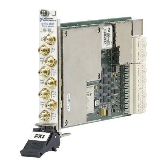
PXIe-6674T
PXI Express Timing and Synchronization Module
The PXIe-6674T enables you to pass PXI timing and trigger signals between PXI Express
chassis. The PXIe-6674T can generate and route clock signals between devices in multiple
chassis, providing a method to synchronize multiple devices in a multichassis PXI Express
system.
This manual describes the electrical and mechanical aspects of the PXIe-6674T and contains
information concerning its operation and programming.
National Instruments Documentation
The PXIe-6674T User Manual is one piece of the documentation set for your measurement
system. You could have any of several other documents describing your hardware and
software. Use the documentation you have as follows:
•
Measurement hardware documentation—This documentation contains detailed
information about the measurement hardware that plugs into or is connected to the
computer. Use this documentation for hardware installation and configuration
instructions, specifications about the measurement hardware, and application hints.
•
Software documentation—Refer to the NI-Sync Help, available at
You can download NI documentation from
Related Documentation
The following documents contain information that you might find helpful as you read this
manual:
•
PICMG 2.0 R3.0, CompactPCI Core Specification, available from PICMG at
www.picmg.org
•
PXI Specification, Revision 2.1, available from
•
NI-VISA User Manual, available from
•
NI-VISA Help, included with the NI-VISA software.
•
NI-Sync User Manual, available from
•
PXIe-6674T Calibration Procedure, available from
.
ni.com/manuals
www.pxisa.org
ni.com/manuals
.
ni.com/manuals
ni.com/manuals
ni.com/manuals
.
.
.
.
.
Advertisement
Table of Contents

Related Manuals for National Instruments PXIe-6674T


Summary of Contents for National Instruments PXIe-6674T
- Page 1 PXIe-6674T PXI Express Timing and Synchronization Module The PXIe-6674T enables you to pass PXI timing and trigger signals between PXI Express chassis. The PXIe-6674T can generate and route clock signals between devices in multiple chassis, providing a method to synchronize multiple devices in a multichassis PXI Express system.
-
Page 2: Table Of Contents
OCXO for improving the stability and accuracy of the PXI Express backplane reference clocks. Unpacking The PXIe-6674T is shipped in an antistatic package to prevent electrostatic damage to the module. Electrostatic discharge (ESD) can damage the module. 2 | ni.com | PXIe-6674T User Manual... -
Page 3: Software Programming Choices
Do not operate the product in a manner not specified in this document. Misuse of the product can result in a hazard. You can compromise the safety protection built into the product if the product is damaged in any way. If the product is damaged, return it to National Instruments for repair. - Page 4 Working voltage is the highest rms value of an AC or DC voltage that can occur across any particular insulation. MAINS is defined as a hazardous live electrical supply system that powers hardware. Suitably rated measuring circuits may be connected to the MAINS for measuring purposes. 4 | ni.com | PXIe-6674T User Manual...
-
Page 5: What You Need To Get Started
The NI-Sync User Manual offers more detailed information on the software used to program the PXIe-6674T. You can find this manual at ni.com/manuals Installing and Configuring This chapter describes how to install the PXIe-6674T hardware and software and how to configure the device. Installing the Software Refer to the file tha accompanies the NI-Sync driver for software installation readme.htm... -
Page 6: Installing The Hardware
ESD protection precautions described in the Unpacking section of the Introduction. Carefully insert the PXIe-6674T into the system timing slot, making sure to not scrape the module on any adjacent modules. Use the injector/ejector handle to fully insert the module into the chassis. -
Page 7: Hardware Overview
Hardware Overview This chapter presents an overview of the hardware functions of the PXIe-6674T. Refer to Figure 2. on page 8 for a functional overview of the PXIe-6674T hardware. PXIe-6674T User Manual | © National Instruments | 7... - Page 8 PFI 2 Driver/ Comparator PCI Express Interface PFI 2 Threshold PFI 3 Driver/ Comparator PFI 3 Threshold LVDS Driver/ Receiver PFI 4 Driver/ Comparator PFI 4 Threshold PFI 5 Driver/ Comparator PFI 5 Threshold 8 | ni.com | PXIe-6674T User Manual...
-
Page 9: Pxie-6674T Front Panel
2. Active LED 5. CLKIN Connector 3. CLKOUT Connector Access LED The Access LED indicates the communication status of the PXIe-6674T. Refer to Figure 3. page 9 for the location of the Access LED. Table 1. on page 10 summarizes what the Access LED colors represent:... -
Page 10: Active Led
Caution If the Access LED is observed to be blinking red, the module has detected an over-temperature condition. Continued use of the PXIe-6674T in this condition is not recommended as product reliability has been compromised. Since several common problems can cause an over-temperature condition, please investigate the following: •... -
Page 11: Connectors
PXIe-6674T front panel. Caution Connections that exceed any of the maximum ratings of input or output signals on the PXIe-6674T can damage the module and the computer. NI is not liable for any damage resulting from such signal connections. Hardware Features The PXIe-6674T performs two broad functions: •... - Page 12 In/Out (to/ The single ended Programmable Function Interface pins from front on the PXIe-6674T route timing and triggering signals panel) between multiple PXI Express chassis. A wide variety of input and output signals can be routed to or from the PFI lines.
- Page 13 The PXI trigger bus consists of eight digital lines shared from among all slots in the PXI Express chassis. The chassis) PXIe-6674T can route a wide variety of signals to and from these lines. Note PXI_TRIG<0..5> are also known as RTSI<0..5>...
-
Page 14: Generating And Routing Clocks
LVDS signaling. Generating and Routing Clocks The PXIe-6674T can generate two types of clock signals. The first clock is generated using the onboard clock generation circuitry, and the second is generated with a precise 10 MHz oscillator. The following sections describe the two types of clock generation and explain the considerations for choosing either type. - Page 15 PXIe_CLK100, its frequency accuracy is inherited from PXIe_CLK100. To give the best frequency accuracy, the OCXO of the PXIe-6674T can be routed to PXI_CLK10_IN, which the chassis can then use to lock PXIe_CLK100 and PXI_CLK10. In addition, using the OCXO will also lower the phase noise of the generated clock frequency.
- Page 16 The OCXO used by the PXIe-6674T features electronic frequency control. This allows the OCXO to be fine-tuned by varying the control voltage to the OCXO. The PXIe-6674T uses a 16-bit digital analog converter to give precise control of the tuning voltage. While the tuning voltage can be varied by the user, it is normally controlled automatically by software, which sets it to the calibration tuning voltage.
- Page 17 OCXO as needed, the 10 MHz PLL of the PXIe-6674T is able to match the OCXO frequency to the reference clock supplied by the user from CLKIN. Use of the 10 MHz PLL of the PXIe-6674T has advantages over using just CLKIN to drive PXI_CLK10_IN: •...
- Page 18 PFI_LVDS cross point switch for routing out the front panel using PFI lines in LVDS mode. Refer to the PFI_LVDS<0..2> section for more information. Note Only clock signals should be routed through the PXIe_DSTARA lines. PXIe_DSTARA lines may exhibit unexpected behavior when routing conventional triggers. 18 | ni.com | PXIe-6674T User Manual...
- Page 19 Table 7. PFI_LVDS Inputs and Outputs Inputs Outputs PXIe_DSTARA Network Bank 0 PFI_LVDS 0 PXIe_DSTARA Network Bank 1 PFI_LVDS 1 PXIe_DSTARA Network Bank 2 PFI_LVDS 2 Clock Generation High Speed CLKOUT PXIe-6674T User Manual | © National Instruments | 19...
-
Page 20: Routing Signals
NI-Sync software will select the low speed or high speed driver automatically based on the source connected to CLKOUT. Routing Signals The PXIe-6674T has versatile trigger routing capabilities. It can route signals to and from the front panel, the PXI star triggers, PXIe_DSTARB, and PXIe_DSTARC. Figure 5. - Page 21 Figure 5. High-Level Schematic of PXIe-6674T Signal Routing Architecture Selection PFI_LVDS 0 Circuitry Selection PXIe_DSTARB 0 PXI_STAR<0..16>, PXI_TRIG<0..7>, Circuitry Selection PFI_LVDS 1 PFI<0..5>, PFI_LVDS<0..2>, Circuitry PXIe_DSTARC<0..16>, Steady Selection PXIe_DSTARB 1 Logic, and Software Trigger are Selection Circuitry PFI_LVDS 2 routed to SOURCE of each Selection Circuitry Circuitry block.
- Page 22 Figure 7. on page 23 summarizes the sources and destinations of the PXIe-6674T. The destinations are listed in the horizontal heading row, and the sources are listed in the column at the far left. A check in a cell indicates that the source and destination combination defined by that cell is a valid routing combination.
- Page 23 Note Terminating the signals with a 50 Ω resistance is recommended when the source is another PXIe-6674T or any other source with a 50 Ω output. The voltage thresholds for the front-panel PFI inputs are programmable. The input signal is generated by comparing the input voltage on the PFI connectors to the voltage output of software-programmable DACs.
- Page 24 When used for trigger routing, the PFI_LVDS signals are routed to and from the FPGA. You can independently select the output signal source for each PFI_LVDS line from one of the following sources: • Another PFI<0..5> • Another PFI pair in LVDS mode. • PXI triggers <0..7> (PXI_TRIG<0..7>) 24 | ni.com | PXIe-6674T User Manual...
- Page 25 You can independently select the output signal source for each PXI trigger line from one of the following sources. • PFI<0..5> • PFI_LVDS<0..2> • Another PXI trigger <0..7> (PXI_TRIG<0..7>) • PXI_STAR<0..16> • Global software trigger • Backplane synchronization clock • PXIe_DSTARC • Steady logic high or low PXIe-6674T User Manual | © National Instruments | 25...
- Page 26 To improve beyond the performance the PXI Star triggers offer in low skew trigger routing, PXI Express implements PXIe_DSTARB and PXIe_DSTARC triggers. Each PXI Express peripheral slot in a PXI Express chassis has independent PXIe_DSTARB and PXIe_DSTARC 26 | ni.com | PXIe-6674T User Manual...
- Page 27 Choosing the Type of Routing The PXIe-6674T routes signals in one of two ways: asynchronously or synchronously. The following sections describe the two routing types and the considerations for choosing each type.
- Page 28 Propagation delay of the signal through the PXIe-6674T. • Time for the receiver to recognize the signal. Both the source and the destination of an asynchronous routing operation on the PXIe-6674T can be any of the following lines: • Any front panel PFI pin (PFI<0..5>) as single ended.
- Page 29 CtoQ Trigger Output The PXIe-6674T board supports synchronous routing to either the rising or falling edge of the synchronization clock. In addition, the polarity of the destination signal can be inverted, which is useful when handling active-low digital signals. Synchronous routing can be useful for eliminating skew when sending triggers to several destinations.
- Page 30 OCXO • CLKIN • One of two "divided copies" of any of the previously listed five signals. The PXIe-6674T includes two clock-divider circuits that can divide the synchronization clock signals by any power of 2 up to 512. Refer to Figure 5.
-
Page 31: Calibration
Calibration consists of verifying the measurement accuracy of a device and correcting for any measurement error. The PXIe-6674T is factory calibrated before shipment at approximately 25 °C to the levels indicated in the PXIe-6674T Specifications. The associated calibration constants—the corrections that were needed to meet specifications—are stored in the onboard nonvolatile memory (EEPROM). -
Page 32: Legal Information
Changes or modifications not expressly approved by National Instruments could void the user's right to operate the hardware under the local regulatory rules. Legal Information... -
Page 33: Limited Warranty
IMPLIED WARRANTIES OF MERCHANTABILITY, FITNESS FOR A PARTICULAR PURPOSE, TITLE OR NON-INFRINGEMENT, AND ANY WARRANTIES THAT MAY ARISE FROM USAGE OF TRADE OR COURSE OF DEALING. NI DOES NOT WARRANT, GUARANTEE, OR MAKE ANY REPRESENTATIONS REGARDING THE PXIe-6674T User Manual | © National Instruments | 33... -
Page 34: Copyright
National Instruments Corporation. National Instruments respects the intellectual property of others, and we ask our users to do the same. NI software is protected by copyright and other intellectual property laws. Where NI... -
Page 35: Trademarks
The mark LabWindows is used under a license from Microsoft Corporation. Windows is a registered trademark of Microsoft Corporation in the United States and other countries. Other product and company names mentioned herein are trademarks or trade names of their respective companies. PXIe-6674T User Manual | © National Instruments | 35... -
Page 36: Patents
Instruments Patent Notice at ni.com/patents. Export Compliance Information Refer to the Export Compliance Information at ni.com/legal/export-compliance the National Instruments global trade compliance policy and how to obtain relevant HTS codes, ECCNs, and other import/export data. WARNING REGARDING USE OF NATIONAL INSTRUMENTS PRODUCTS...
Need help?
Do you have a question about the PXIe-6674T and is the answer not in the manual?
Questions and answers