
Related Manuals for Balluff BTL7-C/E508-M Series


Summary of Contents for Balluff BTL7-C/E508-M Series
- Page 1 BTL7-C/E508-M _ _ _ _ -P-S32/KA _ _ BTL7-C/E509-M _ _ _ _ -P-S32/KA _ _ BTL7-C/E512-M _ _ _ _ -P-S32/KA _ _ BTL7-C/E513-M _ _ _ _ -P-S32/KA _ _ Betriebsanleitung deutsch...
- Page 2 www.balluff.com...
-
Page 3: Table Of Contents
Anschluss der USB-Kommunikationsbox Konfigurationsmöglichkeiten Technische Daten Genauigkeit Umgebungsbedingungen Spannungsversorgung (extern) Ausgang Kommunikationsleitungen La, Lb Maße, Gewichte Zubehör Geführte Positionsgeber Gelenkstange BTL2-GS10-_ _ _ _-A Freie Positionsgeber Steckverbinder und Kabel 8.4.1 BKS-S32/S33M-00, frei konfektionierbar 8.4.2 BKS-S232/S233-PU-_ _, konfektioniert USB-Kommunikationsbox www.balluff.com deutsch... - Page 4 BTL7-C/E5_ _-M _ _ _ _ -P-S32/KA _ _ Micropulse Wegaufnehmer im Profilgehäuse Typenschlüssel Anhang 10.1 Umrechnung Längeneinheiten 10.2 Typenschild deutsch...
-
Page 5: Verwendete Symbole Und Konventionen
Bauformen lieferbar und deshalb gesondert zu – Stoßspannungen (Surge) bestellen. EN 61000-4-5 Schärfegrad 2 – Leitungsgeführte Störgrößen, induziert durch hochfrequente Felder Schärfegrad 3 EN 61000-4-6 – Magnetfelder EN 61000-4-8 Schärfegrad 4 Nähere Informationen zu Richtlinien, Zulassungen und Normen sind in der Konformitätserklärung aufgeführt. www.balluff.com deutsch... -
Page 6: Sicherheit
Die einwandfreie Funktion gemäß den Die verwendeten Warnhinweise enthalten verschiedene Angaben in den technischen Daten wird nur mit original Signalwörter und sind nach folgendem Schema aufgebaut: BALLUFF-Zubehör zugesichert, die Verwendung anderer SIGNALWORT Komponenten bewirkt Haftungsausschluss. Art und Quelle der Gefahr Das Öffnen des Wegaufnehmers oder eine nicht bestim-... -
Page 7: Aufbau Und Funktion
Positionsgeber: Definiert die zu messende Position auf dem Wellenleiter. Positionsgeber sind in unterschiedlichen Bauformen lieferbar und gesondert zu bestellen (siehe Zubehör auf Seite 18). Nennlänge: Um den Wegaufnehmer optimal an die Anwendung anzupassen, sind Nennlängen von 50 mm bis 7620 mm lieferbar. www.balluff.com deutsch... -
Page 8: Funktion
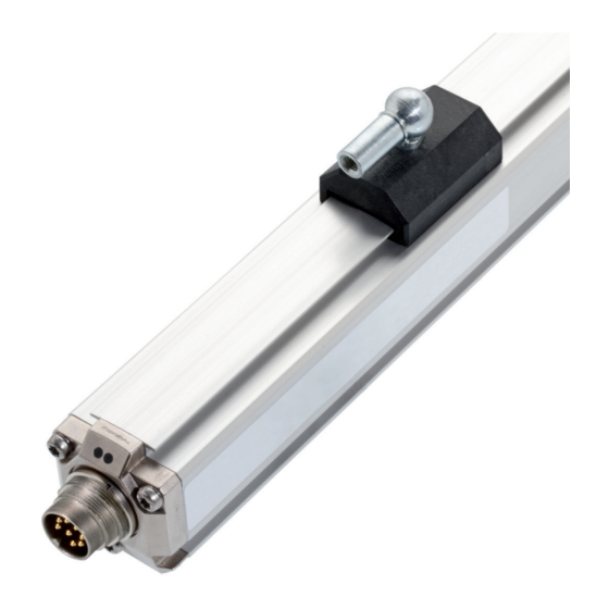
BTL7-C/E5_ _-M _ _ _ _ -P-S32/KA _ _ Micropulse Wegaufnehmer im Profilgehäuse Aufbau und Funktion (Fortsetzung) Funktion LED Anzeige Im Wegaufnehmer BTL7 befindet sich der Wellenleiter, LED 1 LED 2 geschützt durch ein Aluminiumgehäuse. Entlang des Wellenleiters wird ein Positionsgeber bewegt. Dieser Positionsgeber ist mit dem Anlagenbauteil verbunden, des- sen Position bestimmt werden soll. -
Page 9: Einbau Und Anschluss
Bild 4-4 bis Bild 4-8) als auch für geführte Positionsgeber (siehe Bild 4-1 bis Bild 4-3). Bild 4-3: Maße und Abstände mit Positionsgeber BTL5-M/N-2814-1S BTL5-M-2814-1S BTL5-N-2814-1S Abstand X 48,5 mm 57 mm Abstand Y 51 mm 59,5 mm Tab. 4-1: Abstände für Positionsgeber BTL5-M/N-2814-1S www.balluff.com deutsch... -
Page 10: Freie Positionsgeber
BTL7-C/E5_ _-M _ _ _ _ -P-S32/KA _ _ Micropulse Wegaufnehmer im Profilgehäuse Einbau und Anschluss (Fortsetzung) Freie Positionsgeber Beim Einbau des Positionsgebers ist zu beachten: – Um die Genauigkeit des Wegmesssystems zu gewähr- leisten, wird der Positionsgeber mit nichtmagnetisier- baren Schrauben (Edelstahl, Messing, Aluminium) am bewegten Maschinenteil befestigt. -
Page 11: Elektrischer Anschluss
Lb (Kommunikationsleitung) Nicht belegte Adern können steuerungsseitig mit GND verbunden werden, aber nicht mit dem Schirm. Werkseinstellung, mit PC-Software frei konfigurierbar. In PC-Software als Ausgang 2 bezeichnet. Bezugspotenzial für Versorgungs spannung und EMV-GND. Tab. 4-3: Anschlussbelegung BTL7-…-S32/KA_ _ www.balluff.com deutsch... -
Page 12: Schirmung Und Kabelverlegung
BTL7-C/E5_ _-M _ _ _ _ -P-S32/KA _ _ Micropulse Wegaufnehmer im Profilgehäuse Einbau und Anschluss (Fortsetzung) Schirmung und Kabelverlegung Definierte Erdung! Wegaufnehmer und Schaltschrank müssen auf dem gleichen Erdungspotenzial liegen. Schirmung Zur Gewährleistung der elektromagnetischen Verträglich- keit (EMV) sind folgende Hinweise zu beachten: –... -
Page 13: Inbetriebnahme
Hersteller die korrekten Werte im Nullpunkt und Endpunkt prüfen. Hinweise zum Betrieb – Funktion des Wegmesssystems und aller damit ver- bundenen Komponenten regelmäßig überprüfen. – Bei Funktionsstörungen das Wegmesssystem außer Betrieb nehmen. – Anlage gegen unbefugte Benutzung sichern. www.balluff.com deutsch... -
Page 14: Konfiguration Mit Dem Micropulse Configuration Tool
Demo-Modus ohne angeschlossenen Wegaufnehmer USB-Kabel 0,6 m mit Lüster- klemme Die PC-Software und das zugehörige Handbuch erhalten Sie im Internet unter www.balluff.com. Bild 6-2: Anschluss der Kommunikationsbox mit Kabelanschluss Beim Lesen und Schreiben von Daten über das Configuration Tool blinkt LED 2 grün. -
Page 15: Konfigurationsmöglichkeiten
Der zusätzliche Spannungsausgang (Ausgang 2) kann ebenfalls invertiert werden. Ein Ändern des Null- oder Endpunkts wirkt sich ebenfalls auf den zusätzlichen Spannungsaus- gang aus. Auch wenn die Ausgangswerte (Stromausgang) geändert werden, bleibt die Kennlinie des zusätzlichen Spannungsausgangs bei 0…10 V oder 10…0 V. www.balluff.com deutsch... -
Page 16: Technische Daten
Nennlänge 500 mm, Positionsgeber in der Mitte des Messbereichs Für : Gebrauch in geschlossenen Räumen und bis zu einer Höhe von Lagertemperatur −40 °C…+100 °C 2000 m über Meeresspiegel. Luftfeuchtigkeit < 90 %, nicht Einzelbestimmung nach Balluff-Werknorm betauend Resonanzfrequenzen ausgenommen Schockbelastung 150 g/6 ms Für : Der Wegaufnehmer muss extern über einen energiebegrenzten Dauerschock 150 g/2 ms... -
Page 17: Kommunikationsleitungen La, Lb
Kommunikationsleitungen La, Lb Kurzschlussfestigkeit Signalleitung gegen GND Maße, Gewichte Höhe Gehäuse 36,8 mm Nennlänge 50…7620 mm Gewicht (längenabhängig) ca. 1,4 kg/m Gehäusematerial Aluminium BTL7-…-KA_ _ Kabelmaterial cULus 20549 80 °C, 300 V, internal wiring Kabeltemperatur –40 °C…+90 °C Kabeldurchmesser max. 7 mm zulässiger Biegeradius feste Verlegung ≥ 35 mm bewegt ≥ 105 mm www.balluff.com deutsch... -
Page 18: Zubehör
BTL7-C/E5_ _-M _ _ _ _ -P-S32/KA _ _ Micropulse Wegaufnehmer im Profilgehäuse Zubehör Geführte Positionsgeber Gelenkstange BTL2-GS10-_ _ _ _-A Nennlänge BTL5-M/N-2814-1S Mechanisch mit 2 Muttern an Gewindestange M5 fest angelenkt Verstellbereich −5 mm Bild 8-1: Einbaumaße Positionsgeber BTL5-M/N-2814-1S Bild 8-4: Gelenkstange BTL2-GS10-_ _ _ _-A BTL5-M-2814-1S BTL5-N-2814-1S... -
Page 19: Freie Positionsgeber
Gehäuse: Kunststoff Besondere Vorteile des Positionsgebers BTL5-P-4500-1: Mehrere Positionsgeber auf dem gleichen Wegaufnehmer lassen sich getrennt elektrisch ein- und ausschalten (Ansteuerung mit SPS-Signal). BTL6-A-3800-2 37.6 Ø 4.2 Bild 8-7: Einbaumaße Positionsgeber BTL6-A-3800-2 Gewicht: ca. 30 g Gehäuse: Kunststoff www.balluff.com deutsch... -
Page 20: Steckverbinder Und Kabel
BTL7-C/E5_ _-M _ _ _ _ -P-S32/KA _ _ Micropulse Wegaufnehmer im Profilgehäuse Zubehör (Fortsetzung) Steckverbinder und Kabel BKS-S233-PU-_ _ Steckverbinder gewinkelt, umspritzt, konfektioniert M16, 8-polig Unterschiedliche Kabellängen bestellbar, z. B. 8.4.1 BKS-S32/S33M-00, frei konfektionierbar BKS-S233-PU-05: Kabellänge 5 m BKS-S32M-00 Ø 20 Steckverbinder gerade, frei konfektionierbar M16 nach IEC 130-9, 8-polig ~ 62... - Page 21 13 = 1 Ausgang Strom fallend, konfigurierbar + 1 Ausgang Spannung fallend Nennlänge (4-stellig): M0500 = metrische Angabe in mm, Nennlänge 500 mm (M0050…M7620) Bauform: P = Profilgehäuse Elektrischer Anschluss: S32 = 8-polig, M16-Stecker nach IEC 130-9 KA05 = Kabel, 5 m (PUR) www.balluff.com deutsch...
- Page 22 BTL7-C/E5_ _-M _ _ _ _ -P-S32/KA _ _ Micropulse Wegaufnehmer im Profilgehäuse Anhang 10.1 Umrechnung Längeneinheiten 1 mm = 0,0393700787 inch 1 inch = 25,4 mm inch inch 0,03937008 25,4 0,07874016 50,8 0,11811024 76,2 0,15748031 101,6 0,19685039 0,23622047 152,4 0,27559055 177,8 0,31496063...
- Page 23 US Service Center CN Service Center Germany Germany China Balluff GmbH Balluff GmbH Balluff Inc. Balluff (Shanghai) trading Co., ltd. Schurwaldstrasse 9 Schurwaldstrasse 9 8125 Holton Drive Room 1006, Pujian Rd. 145. 73765 Neuhausen a.d.F. 73765 Neuhausen a.d.F. Florence, KY 41042 Shanghai, 200127, P.R.
- Page 24 BTL7-C/E508-M _ _ _ _ -P-S32/KA _ _ BTL7-C/E509-M _ _ _ _ -P-S32/KA _ _ BTL7-C/E512-M _ _ _ _ -P-S32/KA _ _ BTL7-C/E513-M _ _ _ _ -P-S32/KA _ _ User's Guide english...
- Page 25 www.balluff.com...
- Page 26 Accuracy Ambient conditions Supply voltage (external) Output Communication lines La, Lb Dimensions, weights Accessories Captive magnets BTL2-GS10-_ _ _ _-A joint rod Floating magnets Connectors and cables 8.4.1 BKS-S32/S33M-00, freely configurable 8.4.2 BKS-S232/S233-PU-_ _, preassembled USB communication box www.balluff.com english...
- Page 27 BTL7-C/E5_ _-M _ _ _ _ -P-S32/KA _ _ Micropulse Transducer in a Profile Housing Type code breakdown Appendix 10.1 Converting units of length 10.2 Part label english...
-
Page 28: Symbols And Conventions
Severity level 2 – Conducted interference induced by high-frequency fields Severity level 3 EN 61000-4-6 – Magnetic fields EN 61000-4-8 Severity level 4 More detailed information on the guidelines, approvals, and standards is included in the declaration of conformity. www.balluff.com english... -
Page 29: Intended Use
The warnings used here contain various signal words and in accordance with the specifications in the technical data are structured as follows: is ensured only when using original BALLUFF accessories. SIGNAL WORD Use of any other components will void the warranty. -
Page 30: Construction And Function
Magnet: Defines the position to be measured on the waveguide. Magnets are available in various models and must be ordered separately (see Accessories on page 18). Nominal length: To optimally adapt the transducer to the application, nominal lengths from 50 mm to 7620 mm are available. www.balluff.com english... -
Page 31: Function
BTL7-C/E5_ _-M _ _ _ _ -P-S32/KA _ _ Micropulse Transducer in a Profile Housing Construction and function (continued) Function LED display The BTL7 transducer contains the waveguide which is LED 1 LED 2 protected by an aluminum housing. A magnet is moved along the waveguide. -
Page 32: Installation And Connection
(see Fig. 4-1 to Fig. 4-3). Fig. 4-2: Dimensions and distances with BTL5-T-2814-1S magnet Fig. 4-3: Dimensions and distances with BTL5-M/N-2814-1S magnet BTL5-M-2814-1S BTL5-N-2814-1S Distance X 48.5 mm 57 mm Distance Y 51 mm 59.5 mm Tab. 4-1: Distances with BTL5-M/N-2814-1S magnet www.balluff.com english... -
Page 33: Floating Magnets
BTL7-C/E5_ _-M _ _ _ _ -P-S32/KA _ _ Micropulse Transducer in a Profile Housing Installation and connection (continued) Floating magnets The following must be observed when installing the magnet: – To ensure the accuracy of the position measuring system, the magnet is attached to the moving member of the machine using non-magnetizable screws (stainless steel, brass, aluminum). -
Page 34: Electrical Connection
Unassigned leads can be connected to the GND on the controller side but not to the shield. Factory setting, can be freely configured with the PC software. Referred to as output 2 in PC software. Reference potential for supply voltage and EMC-GND. Tab. 4-3: Pin assignment of connector S32/KA_ _ www.balluff.com english... -
Page 35: Shielding And Cable Routing
BTL7-C/E5_ _-M _ _ _ _ -P-S32/KA _ _ Micropulse Transducer in a Profile Housing Installation and connection (continued) Shielding and cable routing Defined ground! The transducer and the control cabinet must be at the same ground potential. Shielding To ensure electromagnetic compatibility (EMC), observe the following: –... -
Page 36: Startup
Operating notes – Check the function of the transducer and all associated components on a regular basis. – Take the position measuring system out of operation whenever there is a malfunction. – Secure the system against unauthorized use. www.balluff.com english... -
Page 37: Configuration With The Micropulse Configuration Tool
– Demo mode without having transducer connected Controller The PC software and associated manual can be 8-pin found in the Internet under www.balluff.com. Connection cable USB cable approx. 0.6 m with luster terminal Fig. 6-2: Connecting the communication box with a cable connection When reading or writing data via the Configuration Tool, LED 2 flashes green. -
Page 38: Configuration Options
The additional voltage output (output 2) can also be inverted. Changing the null or end point also affects the additional voltage output. Even if the output values (current output) are changed, the characteristic curve of the additional voltage output remains at 0…10 V or 10…0 V. www.balluff.com english... -
Page 39: Technical Data
: Use in enclosed spaces and up to a height of 2000 m above sea Storage temperature −40°C…+100°C level. Relative humidity < 90%, Individual specifications as per Balluff factory standard non-condensing Resonant frequencies excluded : The transducer must be externally connected via a limited- Shock rating 150 g/6 ms energy circuit as defined in UL 61010-1, a low-power source as defined in... -
Page 40: Communication Lines La, Lb
Dimensions, weights Housing height 36.8 mm Nominal length 50…7620 mm Weight (depends on length) Approx. 1.4 kg/m Housing material Aluminum BTL7-…-KA_ _ Cable material cULus 20549 80 °C, 300 V, internal wiring Cable temperature –40°C…+90°C Cable diameter Max. 7 mm Permissible bending radius Fixed routing ≥ 35 mm Moved ≥ 105 mm www.balluff.com english... -
Page 41: Accessories
BTL7-C/E5_ _-M _ _ _ _ -P-S32/KA _ _ Micropulse Transducer in a Profile Housing Accessories Captive magnets BTL2-GS10-_ _ _ _-A joint rod Nominal length BTL5-M/N-2814-1S Mechanically joined to M5 stud using 2 nuts Adjustment range −5 mm Fig. 8-1: Installation dimensions of BTL5-M/N-2814-1S magnet Fig. - Page 42 Special advantage of the BTL5-P-4500-1 magnet: Several magnets on the same transducer can be separately switched on and off electrically (actuation BTL6-A-3800-2 with a PLC signal). 37.6 Ø 4.2 Fig. 8-7: Installation dimensions of BTL6-A-3800-2 magnet Weight: Approx. 30 g Housing: Plastic www.balluff.com english...
- Page 43 BTL7-C/E5_ _-M _ _ _ _ -P-S32/KA _ _ Micropulse Transducer in a Profile Housing Accessories (continued) Connectors and cables BKS-S233-PU-_ _ Angled connector, molded, preassembled M16, 8-pin Various cable lengths can be ordered, e.g. BKS-S233-PU-05: Cable length 5 m 8.4.1 BKS-S32/S33M-00, freely configurable Ø...
- Page 44 13 = 1 falling current output, configurable + 1 falling voltage output Nominal stroke (4-digit): M0500 = Metric specification in mm, nominal length 500 mm (M0050…M7620) Construction: P = profile housing Electrical connection: S32 = 8-pin, M16 plug per IEC 130-9 KA05 = Cable, 5 m (PUR) www.balluff.com english...
- Page 45 BTL7-C/E5_ _-M _ _ _ _ -P-S32/KA _ _ Micropulse Transducer in a Profile Housing Appendix 10.1 Converting units of length 1 mm = inch 1 inch = 25.4 mm inches inches 0.03937008 25.4 0.07874016 50.8 0.11811024 76.2 0.15748031 101.6 0.19685039 0.23622047 152.4...
- Page 46 US Service Center CN Service Center Germany Germany China Balluff GmbH Balluff GmbH Balluff Inc. Balluff (Shanghai) trading Co., ltd. Schurwaldstrasse 9 Schurwaldstrasse 9 8125 Holton Drive Room 1006, Pujian Rd. 145. 73765 Neuhausen a.d.F. 73765 Neuhausen a.d.F. Florence, KY 41042 Shanghai, 200127, P.R.
- Page 47 BTL7-C/E508-M _ _ _ _ -P-S32/KA _ _ BTL7-C/E509-M _ _ _ _ -P-S32/KA _ _ BTL7-C/E512-M _ _ _ _ -P-S32/KA _ _ BTL7-C/E513-M _ _ _ _ -P-S32/KA _ _ Manual de instrucciones español...
- Page 48 www.balluff.com...
- Page 49 Salida Líneas de comunicación La, Lb Medidas, pesos Accesorios Sensores de posición guiados Varilla articulada BTL2-GS10-_ _ _ _-A Sensores de posición libres Conectores y cables 8.4.1 BKS-S32/S33M-00, libremente confeccionable 8.4.2 BKS-S232/S233-PU-_ _, confeccionado Módulo de comunicación USB www.balluff.com español...
- Page 50 BTL7-C/E5_ _-M _ _ _ _ -P-S32/KA _ _ Transductor de desplazamiento Micropulse en carcasa perfilada Código de modelo Anexo 10.1 Conversión de unidades de longitud 10.2 Placa de características español...
-
Page 51: Homologaciones E Identificaciones
Grado de severidad 3 EN 61000-4-6 – Campos magnéticos Grado de EN 61000-4-8 severidad 4 En la declaración de conformidad figura más información sobre las directivas, homologaciones y normas. www.balluff.com español... -
Page 52: Seguridad
Las advertencias utilizadas contienen diferentes palabras indicaciones que figuran en los datos técnicos sólo se de señalización y se estructuran según el siguiente garantiza con accesorios originales de BALLUFF; el uso de esquema: otros componentes provoca la exoneración de PALABRA DE SEÑALIZACIÓN responsabilidad. -
Page 53: Estructura Y Funcionamiento
(véase Accesorios en la página 18). Longitud nominal: para adaptar de forma óptima el transductor de desplazamiento a la aplicación, están disponibles longitudes nominales de 50 mm a 7620 mm. www.balluff.com español... -
Page 54: Funcionamiento
BTL7-C/E5_ _-M _ _ _ _ -P-S32/KA _ _ Transductor de desplazamiento Micropulse en carcasa perfilada Estructura y funcionamiento (continuación) Funcionamiento Indicador LED En el transductor de desplazamiento BTL7 se encuentra el LED 1 LED 2 guíaondas, protegido mediante una carcasa de aluminio. A lo largo del guíaondas se mueve un sensor de posición. -
Page 55: Montaje Y Conexión
(véase de la Fig. 4-1 a la Fig. 4-3). Fig. 4-3: Medidas y distancias con el sensor de posición BTL5-M/N-2814-1S BTL5-M-2814-1S BTL5-N-2814-1S Distancia X 48,5 mm 57 mm Distancia Y 51 mm 59,5 mm Tab. 4-1: Distancias del sensor de posición BTL5-M/N-2814-1S www.balluff.com español... -
Page 56: Sensores De Posición Libres
BTL7-C/E5_ _-M _ _ _ _ -P-S32/KA _ _ Transductor de desplazamiento Micropulse en carcasa perfilada Montaje y conexión (continuación) Sensores de posición libres En el montaje del sensor de posición, se debe tener en cuenta lo siguiente: – Para garantizar la precisión del sistema de medición de desplazamiento, el sensor de posición se fija a la pieza móvil de la máquina con tornillos no imantables (acero inoxidable, latón, aluminio). -
Page 57: Conexión Eléctrica
GND, pero no con el blindaje. Ajuste de fábrica, libremente configurable con el software de PC. En el software del PC, denominado como salida 2. Potencial de referencia para la tensión de alimentación y CEM-GND. Tab. 4-3: Ocupación de pines del conector S32/KA_ _ www.balluff.com español... -
Page 58: Blindaje Y Tendido De Cables
BTL7-C/E5_ _-M _ _ _ _ -P-S32/KA _ _ Transductor de desplazamiento Micropulse en carcasa perfilada Montaje y conexión (continuación) Blindaje y tendido de cables Puesta a tierra definida El transductor de desplazamiento y el armario eléctrico deben estar a idéntico potencial de puesta a tierra. -
Page 59: Puesta En Servicio
Compruebe periódicamente el funcionamiento del sistema de medición de desplazamiento y todos los componentes relacionados. – Si se producen fallos de funcionamiento, ponga fuera de servicio el sistema de medición de desplazamiento. – Asegure la instalación contra cualquier uso no autorizado. www.balluff.com español... -
Page 60: Configuración Con La Micropulse Configuration Tool
Fig. 6-2: Conexión del módulo de comunicación con conexión de cable El software de PC y el correspondiente manual se pueden obtener en Internet en la página www.balluff.com. Al leer y escribir datos con la Configuration Tool, el LED 2 parpadea en verde. español... -
Page 61: Posibilidades De Configuración
Una modificación del punto cero o del punto final repercute también en la salida de tensión adicional. Aunque los valores de salida (salida de corriente) se modifiquen, la curva característica de la salida de tensión adicional se mantiene en 0…10 V o 10…0 V. www.balluff.com español... -
Page 62: Datos Técnicos
: uso en espacios cerrados y hasta una altura de 2000 m sobre Humedad del aire < 90 %, el nivel del mar. no condensada Disposición individual según la norma de fábrica de Balluff Carga de choque 150 g/6 ms Frecuencias de resonancias excluidas Choque permanente 150 g/2 ms... -
Page 63: Líneas De Comunicación La, Lb
Peso (en función de la longitud) Aprox. 1,4 kg/m Material de la carcasa Aluminio BTL7-…-KA_ _ Material de cable cULus 20549 80 °C, 300 V, cableado interno Temperatura del cable –40 °C…+90 °C Diámetro del cable Máx. 7 mm Radio de flexión admisible Tendido fijo ≥ 35 mm Móvil ≥ 105 mm www.balluff.com español... -
Page 64: Accesorios
BTL7-C/E5_ _-M _ _ _ _ -P-S32/KA _ _ Transductor de desplazamiento Micropulse en carcasa perfilada Accesorios Sensores de posición guiados Varilla articulada BTL2-GS10-_ _ _ _-A Longitud nominal BTL5-M/N-2814-1S Acoplada firmemente de forma mecánica con dos tuercas al espárrago M5 Zona de ajuste −5 mm Fig. 8-1: Medidas de montaje del sensor de posición BTL5-M/N-2814-1S... - Page 65 BTL5-P-4500-1: varios sensores de posición en el mismo transductor de desplazamiento se pueden conectar y desconectar separados eléctricamente (activación con BTL6-A-3800-2 señal del PLC). 37.6 Ø 4.2 Fig. 8-7: Medidas de montaje del sensor de posición BTL6-A-3800-2 Peso: Aprox. 30 g Carcasa: Material sintético www.balluff.com español...
- Page 66 BTL7-C/E5_ _-M _ _ _ _ -P-S32/KA _ _ Transductor de desplazamiento Micropulse en carcasa perfilada Accesorios (continuación) Conectores y cables BKS-S233-PU-_ _ Conector acodado, recubierto, confeccionado M16, 8 polos Posibilidad de pedir longitudes de cable distintas, 8.4.1 BKS-S32/S33M-00, libremente confeccionable p.
- Page 67 13 = 1 salida de corriente descendente, configurable + 1 salida de tensión descendente Longitud nominal (4 cifras): M0500 = indicación métrica en mm, longitud nominal 500 mm (M0050…M7620) Forma constructiva: P = carcasa perfilada Conexión eléctrica: S32 = 8 polos, conector M16 según IEC 130-9 KA05 = Cable, 5 m (PUR) www.balluff.com español...
- Page 68 BTL7-C/E5_ _-M _ _ _ _ -P-S32/KA _ _ Transductor de desplazamiento Micropulse en carcasa perfilada Anexo 10.1 Conversión de unidades de longitud 1 mm = pulgadas 1 pulgada = 25,4 mm pulgadas pulgadas 0,03937008 25,4 0,07874016 50,8 0,11811024 76,2 0,15748031 101,6 0,19685039...
- Page 69 US Service Center CN Service Center Germany Germany China Balluff GmbH Balluff GmbH Balluff Inc. Balluff (Shanghai) trading Co., ltd. Schurwaldstrasse 9 Schurwaldstrasse 9 8125 Holton Drive Room 1006, Pujian Rd. 145. 73765 Neuhausen a.d.F. 73765 Neuhausen a.d.F. Florence, KY 41042 Shanghai, 200127, P.R.
- Page 70 BTL7-C/E508-M _ _ _ _ -P-S32/KA _ _ BTL7-C/E509-M _ _ _ _ -P-S32/KA _ _ BTL7-C/E512-M _ _ _ _ -P-S32/KA _ _ BTL7-C/E513-M _ _ _ _ -P-S32/KA _ _ Notice d’utilisation français...
- Page 71 www.balluff.com...
- Page 72 Câbles de communication La et Lb Dimensions, poids Accessoires Capteurs de position guidés Tige articulée BTL2-GS10-_ _ _ _-A Capteurs de position libres Connecteurs et câbles 8.4.1 BKS-S32/S33M-00, à assembler 8.4.2 BKS-S232/S233-PU-_ _, confectionné Module de communication USB www.balluff.com français...
- Page 73 BTL7-C/E5_ _-M _ _ _ _ -P-S32/KA _ _ Capteur de déplacement Micropulse en boîtier profilé Code de type Annexe 10.1 Conversion unités de longueur 10.2 Plaque signalétique français...
-
Page 74: Conditionnement
Degré de EN 61000-4-6 sévérité 3 – Champs magnétiques EN 61000-4-8 Degré de sévérité 4 Pour plus d’informations sur les directives, homologations et certifications, se reporter à la déclaration de conformité. www.balluff.com français... -
Page 75: Sécurité
MOT-CLE figurant dans les caractéristiques techniques, n’est garanti qu’avec les accessoires d’origine de BALLUFF, l’utilisation Type et source de danger d’autres composants entraîne la nullité de la garantie. Conséquences en cas de non-respect du danger Un démontage du capteur de déplacement ou une... -
Page 76: Structure Et Fonction
Les capteurs de positions peuvent être fournis sous différentes formes et doivent par conséquent être commandés séparément (voir Accessoires, page 18). Longueur nominale : afin de permettre une adaptation optimale du capteur de déplacement à l’application, des longueurs nominales de 50 mm à 7620 mm sont disponibles. www.balluff.com français... -
Page 77: Fonction
BTL7-C/E5_ _-M _ _ _ _ -P-S32/KA _ _ Capteur de déplacement Micropulse en boîtier profilé Structure et fonction (suite) Fonction Affichage à LED Le capteur de déplacement BTL7 abrite le guide d’ondes LED 1 LED 2 protégé par un boîtier en aluminium. Un capteur de position se déplace le long du guide d’ondes. -
Page 78: Montage Et Raccordement
à Fig. 4-8) qu’aux capteurs de position guidés (voir Fig. 4-1 et Fig. 4-3). Fig. 4-3 : Dimensions et distances pour le capteur de position BTL5-M/N-2814-1S BTL5-M-2814-1S BTL5-N-2814-1S Distance X 48,5 mm 57 mm Distance Y 51 mm 59,5 mm Tab. 4-1 : Distances pour le capteur de position BTL5-M/N-2814-1S www.balluff.com français... -
Page 79: Capteurs De Position Libres
BTL7-C/E5_ _-M _ _ _ _ -P-S32/KA _ _ Capteur de déplacement Micropulse en boîtier profilé Montage et raccordement (suite) Capteurs de position libres A prendre en considération lors du montage du capteur de position : – Pour garantir la précision du système de mesure de déplacement, le capteur de position doit être fixé... -
Page 80: Raccordement Électrique
Réglage usine, configuration libre à l’aide d’un logiciel PC. Désignation en tant que sortie 2 dans le logiciel PC. Potentiel de référence pour tension d’alimentation et GND CEM. Tab. 4-3 : Affectation des broches du connecteur S32 / KA_ _ www.balluff.com français... -
Page 81: Blindage Et Pose Des Câbles
BTL7-C/E5_ _-M _ _ _ _ -P-S32/KA _ _ Capteur de déplacement Micropulse en boîtier profilé Montage et raccordement (suite) Blindage et pose des câbles Mise à la terre définie ! Le capteur de déplacement et l’armoire électrique doivent être reliés au même potentiel de mise à... -
Page 82: Mise En Service
Conseils d’utilisation – Contrôler régulièrement les fonctions du capteur de déplacement et de tous ses composants. – En cas de dysfonctionnement, mettre le système hors service. – Protéger le système de toute utilisation non autorisée. www.balluff.com français... -
Page 83: Configuration Avec Micropulse Configuration Tool
Le logiciel PC ainsi que le manuel correspondant sont disponibles sur notre site Fig. 6-2 : Raccordement du module de communication avec câble Internet www.balluff.com. de raccordement Lors de la lecture et de l’écriture de données via le Configuration Tool, la LED 2 verte clignote. -
Page 84: Possibilités De Configuration
également sur la sortie de tension supplémentaire. Même en cas de modification des valeurs de sortie (sortie de courant), la courbe caractéristique de la sortie de tension supplémentaire reste 0…10 V ou 10…0 V. www.balluff.com français... -
Page 85: Caractéristiques Techniques
: utilisation à l’intérieur et jusqu’à une altitude max. de 2000 m sans condensation au-dessus du niveau de la mer. Résistance aux chocs 150 g/6 ms Détermination individuelle selon la norme d’usine Balluff Chocs permanents 150 g/2 ms Exception faite des fréquences de résonance selon EN 60068-2-27... -
Page 86: Câbles De Communication La Et Lb
Poids (selon la longueur) Env. 1,4 kg/m Matériau du boîtier Aluminium BTL7-…-KA_ _ Matériau du câble cULus 20549 80 °C, 300 V, câblage interne Température de câble –40 °C … +90 °C Diamètre de câble Max. 7 mm Rayon de courbure autorisé Pose fixe ≥ 35 mm Pose mobile ≥ 105 mm www.balluff.com français... -
Page 87: Capteurs De Position Guidés
BTL7-C/E5_ _-M _ _ _ _ -P-S32/KA _ _ Capteur de déplacement Micropulse en boîtier profilé Accessoires Capteurs de position guidés Tige articulée BTL2-GS10-_ _ _ _-A Longueur nominale BTL5-M/N-2814-1S Articulé mécaniquement et solidement par 2 écrous sur tige filetée M5 Plage de réglage −5 mm Fig. - Page 88 BTL5-P-4500-1 : il est possible d’allumer et d’éteindre séparément plusieurs capteurs de position placés sur le BTL6-A-3800-2 même capteur de déplacement (commande par signal API). 37.6 Ø 4.2 Fig. 8-7 : Dimensions de montage du capteur de position BTL6-A-3800-2 Poids : Env. 30 g Boîtier : Plastique www.balluff.com français...
-
Page 89: Connecteurs Et Câbles
BTL7-C/E5_ _-M _ _ _ _ -P-S32/KA _ _ Capteur de déplacement Micropulse en boîtier profilé Accessoires (suite) Connecteurs et câbles BKS-S233-PU-_ _ Connecteur coudé, extrudé, confectionné M16, 8 pôles Différentes longueurs de câble disponibles, 8.4.1 BKS-S32/S33M-00, à assembler p. ex. BKS-S233-PU-05 : longueur de câble 5 m BKS-S32M-00 Ø... - Page 90 Longueur nominale (4 chiffres) : M0500 = Donnée métrique en mm, longueur nominale 500 mm (M0050 … M7620) Forme de construction : P = Boîtier profilé Raccordement électrique : S32 = 8 pôles, connecteur M16 selon IEC 130-9 KA05 = Câble 5 m (PUR) www.balluff.com français...
- Page 91 BTL7-C/E5_ _-M _ _ _ _ -P-S32/KA _ _ Capteur de déplacement Micropulse en boîtier profilé Annexe 10.1 Conversion unités de longueur 1 mm = 0,0393700787 pouce 1 pouce = 25,4 mm pouce pouce 0,03937008 25,4 0,07874016 50,8 0,11811024 76,2 0,15748031 101,6 0,19685039 0,23622047 152,4 0,27559055 177,8 0,31496063...
- Page 92 US Service Center CN Service Center Germany Germany China Balluff GmbH Balluff GmbH Balluff Inc. Balluff (Shanghai) trading Co., ltd. Schurwaldstrasse 9 Schurwaldstrasse 9 8125 Holton Drive Room 1006, Pujian Rd. 145. 73765 Neuhausen a.d.F. 73765 Neuhausen a.d.F. Florence, KY 41042 Shanghai, 200127, P.R.
- Page 93 BTL7-C/E508-M _ _ _ _ -P-S32/KA _ _ BTL7-C/E509-M _ _ _ _ -P-S32/KA _ _ BTL7-C/E512-M _ _ _ _ -P-S32/KA _ _ BTL7-C/E513-M _ _ _ _ -P-S32/KA _ _ Manuale d'uso italiano...
- Page 94 www.balluff.com...
- Page 95 Linee di comunicazione La, Lb Dimensioni, pesi Accessori Datore di posizione guidato Asta di comando BTL2-GS10-_ _ _ _-A Datore di posizione libero Connettori e cavi 8.4.1 BKS-S32/S33M-00, confezionabile liberamente 8.4.2 BKS-S232/S233-PU-_ _, confezionato Scatola di comunicazione USB www.balluff.com italiano...
- Page 96 BTL7-C/E5_ _-M _ _ _ _ -P-S32/KA _ _ Trasduttore di posizione Micropulse in corpo profilato Legenda codici di identificazione Appendice 10.1 Conversione delle unità di lunghezza 10.2 Targhetta identificativa italiano...
- Page 97 Grandezze dei disturbi dalla linea indotte da campi ad alta frequenza EN 61000-4-6 Grado di definizione 3 – Campi magnetici EN 61000-4-8 Grado di definizione 4 Ulteriori informazioni in merito a direttive, autorizzazioni e norme sono indicate nella dichiarazione di conformità. www.balluff.com italiano...
-
Page 98: Uso Conforme
Il funzionamento corretto secondo le indicazioni dei dati schema seguente: tecnici è garantito soltanto con accessori originali PAROLA DI SEGNALAZIONE BALLUFF, l'uso di altri componenti comporta l'esclusione della responsabilità. Natura e fonte del pericolo L'apertura o l'uso improprio del trasduttore di posizione... -
Page 99: Struttura E Funzione
I datori di posizione sono disponibili in varie tipologie costruttive e devono essere ordinati separatamente (vedere Accessori a pagina 18). Lunghezza nominale: per adattare in maniera ottimale il trasduttore di posizione all'applicazione sono disponibili le lunghezze nominali da 50 mm a 7620 mm. www.balluff.com italiano... -
Page 100: Funzionamento
BTL7-C/E5_ _-M _ _ _ _ -P-S32/KA _ _ Trasduttore di posizione Micropulse in corpo profilato Struttura e funzione (continua) Funzionamento Display LED Nel trasduttore di posizione BTL7 si trova la guida d'onda, LED 1 LED 2 protetta da un corpo in alluminio. Lungo la guida d'onda viene spostato un datore di posizione. -
Page 101: Montaggio E Collegamento
Fig. 4-4 alla Fig. 4-8) che per datori di posizione guidati (vedere Fig. 4-1 e Figura Fig. 4-3). Fig. 4-3: Dimensioni e distanze con il datore di posizione BTL5-M/N-2814-1S BTL5-M-2814-1S BTL5-N-2814-1S Distanza X 48,5 mm 57 mm Distanza Y 51 mm 59,5 mm Tab. 4-1: Distanze per il datore di posizione BTL5-M/N-2814-1S www.balluff.com italiano... -
Page 102: Datore Di Posizione Libero
BTL7-C/E5_ _-M _ _ _ _ -P-S32/KA _ _ Trasduttore di posizione Micropulse in corpo profilato Montaggio e collegamento (continua) BTL5-P-5500-2 Datore di posizione libero Durante il montaggio del datore di posizione è necessario tenere presente quanto segue: – Per garantire la precisione del sistema di misura della corsa, il datore di posizione deve essere fissato alla parte della macchina in movimento con viti non magnetizzabili (acciaio inossidabile, ottone, alluminio). -
Page 103: Collegamento Elettrico
I fili non utilizzati possono essere collegati con GND lato controllo, ma non con la schermatura. Impostazioni di fabbrica, configurabili a piacere con il software PC. Nel software PC è contrassegnato come uscita 2. Potenziale di riferimento per tensione di alimentazione e CEM-GND. Tab. 4-3: Piedinatura connettore S32/KA_ _ www.balluff.com italiano... -
Page 104: Schermatura E Posa Dei Cavi
BTL7-C/E5_ _-M _ _ _ _ -P-S32/KA _ _ Trasduttore di posizione Micropulse in corpo profilato Montaggio e collegamento (continua) Schermatura e posa dei cavi Messa a terra definita! Il trasduttore di posizione e l'armadio elettrico devono trovarsi sullo stesso potenziale di terra. Schermatura Per garantire la compatibilità... -
Page 105: Messa In Funzione
Controllare periodicamente il funzionamento del sistema di misura della corsa e di tutti i componenti ad esso collegati. – In caso di anomalie di funzionamento disattivare il sistema di misura della corsa. – Proteggere l'impianto da un uso non autorizzato. www.balluff.com italiano... -
Page 106: Configurazione Con Il Micropulse Configuration Tool
Per il software PC ed il manuale relativo consultare morsetto isolante in Internet l'indirizzo www.balluff.com. Fig. 6-2: Collegamento della scatola di comunicazione con cavo In fase di lettura e scrittura dei dati mediante il Configuration Tool il LED 2 lampeggia di colore verde. -
Page 107: Possibilità Di Configurazione
Una modifica del punto zero o del punto finale agisce anch’essa sull’uscita di tensione supplementare. Anche se i valori di uscita (uscita corrente) vengono modificati, la linea caratteristica dell’uscita di tensione supplementare rimane a 0…10 V oppure 10…0 V. www.balluff.com italiano... -
Page 108: Dati Tecnici
: Uso in spazi chiusi e fino a un’altezza di 2000 m sul livello del Umidità dell'aria < 90%, mare. senza condensa Rilevazione singola secondo la norma interna Balluff Carico da urti 150 g/6 ms Frequenze di risonanza escluse Urto permanente 150 g/2 ms : Il trasduttore di posizione deve essere collegato esternamente secondo EN 60068-2-27... -
Page 109: Linee Di Comunicazione La, Lb
Altezza corpo 36,8 mm Lunghezza nominale 50…7620 mm Peso (in funzione circa 1,4 kg/m della lunghezza) Materiale corpo alluminio BTL7-…-KA_ _ Materiale cavo cULus 20549 80°C, 300 V, cablaggio interno Temperatura cavo –40 °C…+90 °C Diametro del cavo max. 7 mm Raggio di curvatura consentito Posa fissa ≥ 35 mm Mobile ≥ 105 mm www.balluff.com italiano... -
Page 110: Accessori
BTL7-C/E5_ _-M _ _ _ _ -P-S32/KA _ _ Trasduttore di posizione Micropulse in corpo profilato Accessori Datore di posizione guidato Asta di comando BTL2-GS10-_ _ _ _-A Lunghezza nominale BTL5-M/N-2814-1S Incernieratura meccanica fissa su asta filettata M5 con 2 dadi Campo di regolazione −5 mm Fig. -
Page 111: Datore Di Posizione Libero
(comando con BTL6-A-3800-2 segnale SPS). 37.6 Ø 4.2 Fig. 8-7: Dimensioni di ingombro datore di posizione BTL6-A-3800-2 Peso: ca. 30 g Corpo: materiale plastico www.balluff.com italiano... -
Page 112: Connettori E Cavi
BTL7-C/E5_ _-M _ _ _ _ -P-S32/KA _ _ Trasduttore di posizione Micropulse in corpo profilato Accessori (continua) Connettori e cavi BKS-S233-PU-_ _ Connettore ad angolo, incorporato, confezionato M16, a 8 poli È possibile ordinare diverse lunghezze del cavo, 8.4.1 BKS-S32/S33M-00, confezionabile liberamente p. es. - Page 113 13 = 1 uscita corrente discendente, configurabile + 1 uscita tensione discendente Lunghezza nominale (a 4 cifre): M0500 = indicazione metrica in mm, lunghezza nominale 500 mm (M0050…M7620) Forma costruttiva: P = corpo profilato Collegamento elettrico: S32 = Connettore M16 a 8 poli secondo IEC 130-9 KA05 = Cavo, 5 m www.balluff.com italiano...
- Page 114 BTL7-C/E5_ _-M _ _ _ _ -P-S32/KA _ _ Trasduttore di posizione Micropulse in corpo profilato Appendice 10.1 Conversione delle unità di lunghezza 1 mm = 0,0393700787 pollici 1 pollice = 25,4 mm pollice pollice 0,03937008 25,4 0,07874016 50,8 0,11811024 76,2 0,15748031 101,6...
- Page 115 US Service Center CN Service Center Germany Germany China Balluff GmbH Balluff GmbH Balluff Inc. Balluff (Shanghai) trading Co., ltd. Schurwaldstrasse 9 Schurwaldstrasse 9 8125 Holton Drive Room 1006, Pujian Rd. 145. 73765 Neuhausen a.d.F. 73765 Neuhausen a.d.F. Florence, KY 41042 Shanghai, 200127, P.R.
Need help?
Do you have a question about the BTL7-C/E508-M Series and is the answer not in the manual?
Questions and answers